EP4535899A1 - Procédé et appareil de transmission et de réception d'une ppdu basée sur une trame de déclenchement dans un système lan sans fil - Google Patents
Procédé et appareil de transmission et de réception d'une ppdu basée sur une trame de déclenchement dans un système lan sans fil Download PDFInfo
- Publication number
- EP4535899A1 EP4535899A1 EP23816381.0A EP23816381A EP4535899A1 EP 4535899 A1 EP4535899 A1 EP 4535899A1 EP 23816381 A EP23816381 A EP 23816381A EP 4535899 A1 EP4535899 A1 EP 4535899A1
- Authority
- EP
- European Patent Office
- Prior art keywords
- information
- channel
- mhz
- ppdu
- sta
- Prior art date
- Legal status (The legal status is an assumption and is not a legal conclusion. Google has not performed a legal analysis and makes no representation as to the accuracy of the status listed.)
- Pending
Links
Images






Classifications
-
- H—ELECTRICITY
- H04—ELECTRIC COMMUNICATION TECHNIQUE
- H04W—WIRELESS COMMUNICATION NETWORKS
- H04W74/00—Wireless channel access
- H04W74/08—Non-scheduled access, e.g. ALOHA
- H04W74/0808—Non-scheduled access, e.g. ALOHA using carrier sensing, e.g. carrier sense multiple access [CSMA]
- H04W74/0816—Non-scheduled access, e.g. ALOHA using carrier sensing, e.g. carrier sense multiple access [CSMA] with collision avoidance
-
- H—ELECTRICITY
- H04—ELECTRIC COMMUNICATION TECHNIQUE
- H04L—TRANSMISSION OF DIGITAL INFORMATION, e.g. TELEGRAPHIC COMMUNICATION
- H04L5/00—Arrangements affording multiple use of the transmission path
- H04L5/0091—Signalling for the administration of the divided path, e.g. signalling of configuration information
- H04L5/0092—Indication of how the channel is divided
-
- H—ELECTRICITY
- H04—ELECTRIC COMMUNICATION TECHNIQUE
- H04L—TRANSMISSION OF DIGITAL INFORMATION, e.g. TELEGRAPHIC COMMUNICATION
- H04L5/00—Arrangements affording multiple use of the transmission path
- H04L5/0091—Signalling for the administration of the divided path, e.g. signalling of configuration information
- H04L5/0094—Indication of how sub-channels of the path are allocated
-
- H—ELECTRICITY
- H04—ELECTRIC COMMUNICATION TECHNIQUE
- H04W—WIRELESS COMMUNICATION NETWORKS
- H04W72/00—Local resource management
- H04W72/04—Wireless resource allocation
- H04W72/044—Wireless resource allocation based on the type of the allocated resource
- H04W72/0453—Resources in frequency domain, e.g. a carrier in FDMA
-
- H—ELECTRICITY
- H04—ELECTRIC COMMUNICATION TECHNIQUE
- H04W—WIRELESS COMMUNICATION NETWORKS
- H04W72/00—Local resource management
- H04W72/04—Wireless resource allocation
-
- H—ELECTRICITY
- H04—ELECTRIC COMMUNICATION TECHNIQUE
- H04W—WIRELESS COMMUNICATION NETWORKS
- H04W72/00—Local resource management
- H04W72/20—Control channels or signalling for resource management
- H04W72/23—Control channels or signalling for resource management in the downlink direction of a wireless link, i.e. towards a terminal
-
- H—ELECTRICITY
- H04—ELECTRIC COMMUNICATION TECHNIQUE
- H04W—WIRELESS COMMUNICATION NETWORKS
- H04W74/00—Wireless channel access
- H04W74/08—Non-scheduled access, e.g. ALOHA
-
- H—ELECTRICITY
- H04—ELECTRIC COMMUNICATION TECHNIQUE
- H04W—WIRELESS COMMUNICATION NETWORKS
- H04W84/00—Network topologies
- H04W84/02—Hierarchically pre-organised networks, e.g. paging networks, cellular networks, WLAN [Wireless Local Area Network] or WLL [Wireless Local Loop]
- H04W84/10—Small scale networks; Flat hierarchical networks
- H04W84/12—WLAN [Wireless Local Area Networks]
Definitions
- the present disclosure relates to a method and device for transmitting or receiving a physical layer protocol data unit (PPDU) based on a trigger frame in a wireless local area network (WLAN) system.
- PPDU physical layer protocol data unit
- EHT Extremely High Throughput
- MIMO Multiple Input Multiple Output
- APs multiple access points
- UHR ultra high reliability
- a technical object of the present disclosure is to provide a method and device for transmitting or receiving a physical layer protocol data unit (PPDU) based on a trigger frame in a wireless LAN system.
- PPDU physical layer protocol data unit
- One or more processors 102, 202 may receive a signal (e.g., a baseband signal) from one or more transceivers 106, 206 and obtain a PDU, a SDU, a message, control information, data or information according to description, functions, procedures, proposals, methods and/or operation flow charts disclosed in the present disclosure.
- a signal e.g., a baseband signal
- One or more processors 102, 202 may be referred to as a controller, a micro controller, a micro processor or a micro computer.
- One or more processors 102, 202 may be implemented by a hardware, a firmware, a software, or their combination.
- one or more ASICs Application Specific Integrated Circuit
- one or more DSPs Digital Signal Processor
- one or more DSPDs Digital Signal Processing Device
- one or more PLDs PROgrammable Logic Device
- FPGAs Field Programmable Gate Arrays
- one or more processors 102, 202 may control one or more transceivers 106, 206 to transmit user data, control information or a wireless signal to one or more other devices.
- one or more processors 102, 202 may control one or more transceivers 106, 206 to receive user data, control information or a wireless signal from one or more other devices.
- one or more transceivers 106, 206 may be connected to one or more antennas 108, 208 and one or more transceivers 106, 206 may be configured to transmit and receive user data, control information, a wireless signal/channel, etc. mentioned in description, functions, procedures, proposals, methods and/or operation flow charts, etc.
- one or more antennas may be a plurality of physical antennas or a plurality of logical antennas (e.g., an antenna port).
- One or more transceivers 106, 206 may convert a received wireless signal/channel, etc. into a baseband signal from a RF band signal to process received user data, control information, wireless signal/channel, etc. by using one or more processors 102, 202.
- One or more transceivers 106, 206 may convert user data, control information, a wireless signal/channel, etc. which are processed by using one or more processors 102, 202 from a baseband signal to a RF band signal.
- one or more transceivers 106, 206 may include an (analogue) oscillator and/or a filter.
- an example of an operation of generating a transmission/reception signal or performing data processing or calculation in advance for the transmission/reception signal may include 1) Determining / acquiring / configuring / calculating / decoding / encoding bit information of fields (signal (SIG), short training field (STF), long training field (LTF), Data, etc.) included in the PPDU, 2) Determining / configuring / acquiring time resources or frequency resources (e.g., subcarrier resources) used for fields (SIG, STF, LTF, Data, etc.) included in the PPDU; 3) Determining / configuring / acquiring a specific sequence (e.g., pilot sequence, STF/LTF sequence, extra sequence applied to SIG) used for fields (SIG, STF, LTF, Data, etc.) included in the PPDU action, 4) power control operation and/or power saving operation applied to the STA, 5) Operations related to ACK signal determination/acquisition/configuration/calculation/decoding/en
- an ad-hoc network When an ad-hoc network operates in a location where an ESS network exists, when physically overlapping wireless networks are configured by different organizations, or when two or more different access and security policies are required in the same location, this may correspond to the form of an ESS network in the like.
- FIG. 3 is a diagram for explaining a link setup process to which the present disclosure may be applied.
- the STA may transmit an authentication request frame to the AP.
- the AP may determine whether to allow authentication of the corresponding STA based on information included in the received authentication request frame.
- the AP may provide the result of the authentication process to the STA through an authentication response frame.
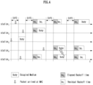
- FIG. 4 is a diagram for explaining a backoff process to which the present disclosure may be applied.
- the corresponding AP and/or STA does not start its own transmission and may set a delay period for medium access (e.g., a random backoff period) and attempt frame transmission after waiting.
- a delay period for medium access e.g., a random backoff period
- collision may be minimized.
- CW parameter value When the CW parameter value reaches CWmax, data transmission may be attempted while maintaining the CWmax value until data transmission is successful, and when data transmission is successful, the CWmin value is reset.
- the STA continuously monitors the medium while counting down the backoff slots according to the determined backoff count value.
- the medium is monitored for occupancy, it stops counting down and waits, and resumes the rest of the countdown when the medium becomes idle.
- STA3 may transmit the frame immediately after confirming that the medium is idle as much as DIFS. The remaining STAs monitor and wait for the medium to be occupied/busy. In the meantime, data to be transmitted may also occur in each of STA1, STA2, and STA5, and each STA waits as long as DIFS when the medium is monitored as idle, and then may perform a countdown of the backoff slot according to the random backoff count value selected by each STA. Assume that STA2 selects the smallest backoff count value and STA1 selects the largest backoff count value.
- STA1 and STA5 temporarily stop counting down and wait while STA2 occupies the medium.
- STA1 and STA5 wait for DIFS and resume the stopped backoff count. That is, frame transmission may be started after counting down the remaining backoff slots for the remaining backoff time. Since the remaining backoff time of STA5 is shorter than that of STA1, STA5 starts frame transmission. While STA2 occupies the medium, data to be transmitted may also occur in STA4.
- control frame As a subtype frames of control frame, there are Request-To-Send (RTS), Clear-To-Send (CTS), Acknowledgement (ACK), Power Save-Poll (PS-Poll), block ACK (BlockAck), block ACK request ( BlockACKReq), null data packet announcement (NDP announcement), and trigger, etc.
- RTS Request-To-Send
- CTS Clear-To-Send
- ACK Acknowledgement
- PS-Poll Power Save-Poll
- BlockAck block ACK
- BlockACKReq block ACK request
- NDP announcement null data packet announcement
- a Quality of Service (QoS) STA may perform the backoff that is performed after an arbitration IFS (AIFS) for an access category (AC) to which the frame belongs, that is, AIFS[i] (where i is a value determined by AC), and then may transmit the frame.
- AIFS arbitration IFS
- AC access category
- the frame in which AIFS[i] can be used may be a data frame, a management frame, or a control frame other than a response frame.
- a mechanism using RTS/CTS frames may be applied.
- the medium is in an idle state. That is, the STA1 may correspond to a hidden node to the STA3.
- it may be determined that the carrier sensing result medium of the STA3 is in an idle state while transmission of the STA2 is being performed. That is, the STA2 may correspond to a hidden node to the STA3.
- RUs corresponding to different numbers of tones are used to construct some fields of 20 MHz, 40 MHz, or 80 MHz X-PPDUs (X is HE, EHT, etc.).
- X is HE, EHT, etc.
- resources may be allocated in RU units shown for the X-STF, X-LTF, and Data field.
- RUs of various sizes that is, 26-RU, 52-RU, 106-RU, 242-RU, etc. are exemplified, but the specific size of these RUs may be reduced or expanded. Therefore, in the present disclosure, the specific size of each RU (i.e., the number of corresponding tones) is exemplary and not restrictive. In addition, within a predetermined bandwidth (e.g., 20, 40, 80, 160, 320 MHz, ...) in the present disclosure, the number of RUs may vary according to the size of the RU. In the examples of FIG. 9 and/or FIG. 10 to be described below, the fact that the size and/or number of RUs may be varied is the same as the example of FIG. 8 .
- 26-RU, 52-RU, 106-RU, 242-RU, 484-RU, and the like may be used in the example of FIG. 9 as well.
- 5 DC tones may be inserted at the center frequency
- 12 tones may be used as a guard band in the leftmost band of the 40MHz band
- 11 tones may be used as a guard band in the rightmost band of the 40MHz band.
- 996-RU when used for a single user, 996-RU may be used, and in this case, 5 DC tones are inserted in common with HE PPDU and EHT PPDU.
- the plurality of RUs constituting one MRU may correspond to small size (e.g., 26, 52, or 106) RUs or large size (e.g., 242, 484, or 996) RUs. That is, one MRU including a small size RU and a large size RU may not be configured/defined. In addition, a plurality of RUs constituting one MRU may or may not be consecutive in the frequency domain.
- the RU of the present disclosure may be used for uplink (UL) and/or downlink (DL) communication.
- the STA transmitting the trigger e.g., AP
- trigger information e.g., trigger frame or triggered response scheduling (TRS)
- the common field may include N*8 RU allocation subfields.
- One 8-bit RU allocation subfield may indicate the size (26, 52, 106, etc.) and frequency location (or RU index) of RUs included in the 20 MHz band.
- a value of the 8-bit RU allocation subfield is 00000000, it may indicate that nine 26-RUs are sequentially allocated in order from the leftmost to the rightmost in the example of FIG. 8 , if the value is 00000001, it may indicate that seven 26-RUs and one 52-RU are sequentially allocated in order from leftmost to rightest, and if the value is 00000010, it may indicate that five 26-RUs, one 52-RU, and two 26-RUs are sequentially allocated from the leftmost side to the rightmost side.
- FIG. 12 is a diagram for explaining a MU-MIMO method in which a plurality of users/STAs are allocated to one RU.
- the user field may be constructed based on two formats.
- the user field for a MU-MIMO allocation may be constructed with a first format
- the user field for non-MU-MIMO allocation may be constructed with a second format.
- user fields 1 to 3 may be based on the first format
- user fields 4 to 8 may be based on the second format.
- the first format and the second format may contain bit information of the same length (e.g., 21 bits).
- the user field of the first format (i.e., format for MU-MIMO allocation) may be constructed as follows. For example, out of all 21 bits of one user field, B0-B10 includes the user's identification information (e.g., STA-ID, AID, partial AID, etc.), B11-14 includes spatial configuration information such as the number of spatial streams for the corresponding user, B15-B18 includes Modulation and Coding Scheme (MCS) information applied to the Data field of the corresponding PPDU, B19 is defined as a reserved field, and B20 may include information on a coding type (e.g., binary convolutional coding (BCC) or low-density parity check (LDPC)) applied to the Data field of the corresponding PPDU.
- BCC binary convolutional coding
- LDPC low-density parity check
- MCS MCS information
- MCS index MCS field, and the like used in the present disclosure may be indicated by a specific index value.
- MCS information may be indicated as index 0 to index 11.
- MCS information includes information on constellation modulation type (e.g., BPSK, QPSK, 16-QAM, 64-QAM, 256-QAM, 1024-QAM, etc.), and coding rate (e.g., 1/2, 2/ 3, 3/4, 5/6, etc.).
- coding rate e.g., 1/2, 2/ 3, 3/4, 5/6, etc.
- Information on a channel coding type e.g., BCC or LDPC
- BCC channel coding type
- the EHT-SIG is omitted compared to the EHT MU PPDU.
- the STA may perform UL transmission based on the EHT TB PPDU format.
- the L-SIG field of FIG. 13 may be constructed with 24 bits and may be used to communicate rate and length information.
- the L-SIG field includes a 4-bit Rate field, a 1-bit Reserved bit, a 12-bit Length field, a 1-bit Parity field, and a 6-bit Tail field may be included.
- the 12-bit Length field may include information on a time duration or a length of the PPDU.
- a value of the 12-bit Length field may be determined based on the type of PPDU. For example, for a non-HT, HT, VHT, or EHT PPDU, the value of the Length field may be determined as a multiple of 3. For example, for the HE PPDU, the value of the Length field may be determined as a multiple of 3 + 1 or a multiple of 3 + 2.
- 48 BPSK symbols may be mapped to subcarrier indices -26 to -22, -20 to -8, -6 to -1, +1 to +6, +8 to +20, and +22 to +26.
- the transmitting STA may additionally map the signals of ⁇ -1, -1, -1, 1 ⁇ to the subcarrier index ⁇ -28, -27, +27, +28 ⁇ .
- the above signal may be used for channel estimation in the frequency domain corresponding to ⁇ -28, -27, +27, +28 ⁇ .
- the U-SIG may include N-bit information and may include information for identifying the type of EHT PPDU.
- U-SIG may be configured based on two symbols (e.g., two consecutive OFDM symbols).
- Each symbol (e.g., OFDM symbol) for the U-SIG may have a duration of 4us, and the U-SIG may have a total 8us duration.
- Each symbol of the U-SIG may be used to transmit 26 bit information.
- each symbol of the U-SIG may be transmitted and received based on 52 data tones and 4 pilot tones.
- a bit information (e.g., 52 un-coded bits) may be transmitted
- the first symbol of the U-SIG (e.g., U-SIG-1) may transmit the first X bit information (e.g., 26 un-coded bits) of the total A bit information
- the second symbol of the U-SIG (e.g., U-SIG-2) may transmit the remaining Y-bit information (e.g., 26 un-coded bits) of the total A-bit information.
- the transmitting STA may obtain 26 un-coded bits included in each U-SIG symbol.
- the U-SIG and the EHT-SIG may include information on preamble puncturing based on the following method. If the bandwidth of the PPDU exceeds 80 MHz, the U-SIG may be individually constructed in units of 80 MHz. For example, if the bandwidth of the PPDU is 160 MHz, the PPDU may include a first U-SIG for a first 80 MHz band and a second U-SIG for a second 80 MHz band. In this case, the first field of the first U-SIG includes information on the 160 MHz bandwidth, and the second field of the first U-SIG includes information on preamble puncturing applied to the first 80 MHz band (i.e., information on a preamble puncturing pattern).
- a mode in which a common field of EHT-SIG is omitted may be supported.
- the mode in which the common field of the EHT-SIG is omitted may be referred as a compressed mode.
- a plurality of users (i.e., a plurality of receiving STAs) of the EHT PPDU may decode the PPDU (e.g., the data field of the PPDU) based on non-OFDMA. That is, a plurality of users of the EHT PPDU may decode a PPDU (e.g., a data field of the PPDU) received through the same frequency band.
- Information on the type of STF and/or LTF may be included in the U-SIG field and/or the EHT-SIG field of FIG. 13 .
- GI guard interval
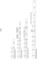
- a common information field may include information commonly applied to at least one TB PPDU transmission requested by a trigger frame, e.g., a trigger type, a UL length, whether a subsequent trigger frame exists (e.g., More TF), whether channel sensing (CS) is required, a UL bandwidth (BW), etc.
- FIG. 14 illustratively shows a EHT variant common information field format.
- a AID12 subfield is basically a user information field for a STA having a corresponding AID.
- a AID12 field may be utilized for other purpose including allocating a random access (RA)-RU or being configured in a form of a special user information field.
- a special user information field is a user information field which does not include user-specific information but includes extended common information not provided in a common information field. For example, a special user information field may be identified by an AID12 value of 2007 and a special user information field flag subfield in a common information field may represent whether a special user information field is included.
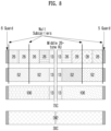
- the 160 MHz channels may be expressed as a primary (or first) 160 MHz channel, a secondary 160 MHz channel, and a third 160 MHz channel (or a 160 MHz channel in a relatively low frequency range within the secondary 320 MHz), and the 80 MHz channel may be expressed as a fourth channel, 80 MHz channel in a relatively low frequency range.
- RU/MRU allocation for triggering/requesting TB PPDU transmission over the extended BW may be configured/indicated based on at least one of the following embodiments.
- RU/MRU allocation (field) transmitted through trigger frame may indicate 160MHz channel to which RU/MRU is allocated by using B25 (i.e., 160 extension field) and B39 (i.e., PS160 field) included in user field.
- B25 i.e., 160 extension field
- B39 i.e., PS160 field
- information of B25 and B39 may be used to indicate in which 160MHz channel the RU/MRU for the TB PPDU is located/included.
- the B0 bit of the allocation field i.e., the RU allocation field
- information on which 80MHz channel location within 160MHz indicated by the above-mentioned two bits (i.e., B25 and B39) the allocated RU/MRU exists may be indicated.
- Table 1 may also be configured with a combination of (B25 B39).
- 2-bit (B39 B25) may always be set to (0, 0).
- This embodiment relates to a method of using 2-bit information for RU/MRU allocation for extended BW.
- a PS320 field may be defined for indicating 320MHz in the extended BW, and the PS320 field may be composed of 1-bit information.
- the 1-bit information may be B25 of the user field in the trigger frame.
- the field name is an example, and may be redefined with another field name.
- the extended BW may be configured as a combination of a 320 MHz channel and a 160 MHz channel.
- the PS320 field may be set to a value of 0 when the RU/MRU exists in the primary 320 MHz channel, and may be set to a value of 1 when the RU/MRU exists in a 160 MHz channel (e.g., a relatively lower 160 MHz channel within the secondary 320 MHz channel).
- the extended BW when the extended BW corresponds to a 560 MHz bandwidth, the extended BW may be configured with a combination of a 320 MHz channel and a 240 MHz channel, or a combination of a 320 MHz channel, a 160 MHz channel, and an 80 MHz channel.
- a combination of a 240MHz channel / a 160MHz channel and an 80MHz channel may be considered as a channel configuration included in one of the two 320MHz channels. Therefore, a combination of a 240MHz channel / a 160MHz channel and an 80MHz channel may be indicated via the PS320 field.
- the PS320 field/bit may be used to set/indicate one of the two 320MHz depending on the location of the allocated RU/MRU.
- the PS320 field/bit may be used to set/indicate one of the two 320MHz depending on the location of the allocated MRU.
- the TRS control field may include 160 extension bits (1-bit) for indicating 160MHz channel units.
- 160 extension bits (1-bit) for indicating 160MHz channel units.
- the TRS control field may include a 160 indication field consisting of 2 bits. Using the 2-bit value, a 160 MHz channel containing the allocated RU/MRU as described above may be indicated.
- the combination may indicate one of a first 160 MHz channel within a primary 320 MHz channel, a second 160 MHz channel within a primary 320 MHz channel, a first 160 MHz channel within a secondary 320 MHz channel, or a second 160 MHz channel within a secondary 320 MHz channel.
- the first information may correspond to information indicating whether it is a primary 320 MHz channel or a secondary 320 MHz channel (e.g., bit B39 of the user information field).
- the second information may correspond to information indicating a location of a 160 MHz channel within the primary channel or the secondary channel (e.g., bit B25 of the user information field).
- resources for the TB PPDU may be allocated in resource unit (RU) or multiple RU (MRU) units.
- the user info field may include first information and second information related to channel indication.
- the first information and the second information may each be composed of 1-bit information.
- the trigger frame proposed in the present disclosure has a new feature of further including information for indicating the location of a channel to which RU/MRU resources are allocated considering the extended BW.
- Embodiments described above are that elements and features of the present disclosure are combined in a predetermined form. Each element or feature should be considered to be optional unless otherwise explicitly mentioned. Each element or feature may be implemented in a form that it is not combined with other element or feature.
- an embodiment of the present disclosure may include combining a part of elements and/or features. An order of operations described in embodiments of the present disclosure may be changed. Some elements or features of one embodiment may be included in other embodiment or may be substituted with a corresponding element or a feature of other embodiment. It is clear that an embodiment may include combining claims without an explicit dependency relationship in claims or may be included as a new claim by amendment after application.
- a scope of the present disclosure includes software or machine-executable commands (e.g., an operating system, an application, a firmware, a program, etc.) which execute an operation according to a method of various embodiments in a device or a computer and a non-transitory computer-readable medium that such a software or a command, etc. are stored and are executable in a device or a computer.
- a command which may be used to program a processing system performing a feature described in the present disclosure may be stored in a storage medium or a computer-readable storage medium and a feature described in the present disclosure may be implemented by using a computer program product including such a storage medium.
- a storage medium may include a high-speed random-access memory such as DRAM, SRAM, DDR RAM or other random-access solid state memory device, but it is not limited thereto, and it may include a nonvolatile memory such as one or more magnetic disk storage devices, optical disk storage devices, flash memory devices or other nonvolatile solid state storage devices.
- a memory optionally includes one or more storage devices positioned remotely from processor(s).
- a memory or alternatively, nonvolatile memory device(s) in a memory include a non-transitory computer-readable storage medium.
- a method proposed by the present disclosure is mainly described based on an example applied to an IEEE 802.11-based system, 5G system, but may be applied to various WLAN or wireless communication systems other than the IEEE 802.11-based system.
Landscapes
- Engineering & Computer Science (AREA)
- Signal Processing (AREA)
- Computer Networks & Wireless Communication (AREA)
- Mobile Radio Communication Systems (AREA)
Applications Claiming Priority (2)
| Application Number | Priority Date | Filing Date | Title |
|---|---|---|---|
| KR20220068376 | 2022-06-03 | ||
| PCT/KR2023/007503 WO2023234721A1 (fr) | 2022-06-03 | 2023-06-01 | Procédé et appareil de transmission et de réception d'une ppdu basée sur une trame de déclenchement dans un système lan sans fil |
Publications (1)
| Publication Number | Publication Date |
|---|---|
| EP4535899A1 true EP4535899A1 (fr) | 2025-04-09 |
Family
ID=89025210
Family Applications (1)
| Application Number | Title | Priority Date | Filing Date |
|---|---|---|---|
| EP23816381.0A Pending EP4535899A1 (fr) | 2022-06-03 | 2023-06-01 | Procédé et appareil de transmission et de réception d'une ppdu basée sur une trame de déclenchement dans un système lan sans fil |
Country Status (6)
| Country | Link |
|---|---|
| US (1) | US20250358847A1 (fr) |
| EP (1) | EP4535899A1 (fr) |
| JP (1) | JP7780671B2 (fr) |
| KR (1) | KR20250004294A (fr) |
| CN (1) | CN119302021A (fr) |
| WO (1) | WO2023234721A1 (fr) |
Family Cites Families (6)
| Publication number | Priority date | Publication date | Assignee | Title |
|---|---|---|---|---|
| KR102082093B1 (ko) * | 2017-01-09 | 2020-02-27 | 주식회사 윌러스표준기술연구소 | 다중 사용자 패킷의 시그널링을 위한 무선 통신 방법 및 무선 통신 단말 |
| US11160084B2 (en) * | 2018-07-05 | 2021-10-26 | Qualcomm Incorporated | Supporting 320 MHz operating BW |
| EP4156818A4 (fr) | 2020-05-18 | 2024-06-19 | LG Electronics, Inc. | Transmission d'une trame de déclenchement dans un système de communication sans fil |
| KR20250030019A (ko) | 2020-09-07 | 2025-03-05 | 엘지전자 주식회사 | 무선랜 시스템에서 mld 간 링크에 대한 정보를 획득하는 방법 및 장치 |
| CN116528371B (zh) | 2020-10-28 | 2024-02-13 | 华为技术有限公司 | Ppdu的上行带宽指示方法及相关装置 |
| US11515982B2 (en) | 2020-11-12 | 2022-11-29 | Qualcomm Incorporated | Special user information field for trigger frame |
-
2023
- 2023-06-01 JP JP2024571163A patent/JP7780671B2/ja active Active
- 2023-06-01 CN CN202380044511.0A patent/CN119302021A/zh active Pending
- 2023-06-01 US US18/869,560 patent/US20250358847A1/en active Pending
- 2023-06-01 EP EP23816381.0A patent/EP4535899A1/fr active Pending
- 2023-06-01 WO PCT/KR2023/007503 patent/WO2023234721A1/fr not_active Ceased
- 2023-06-01 KR KR1020247038281A patent/KR20250004294A/ko active Pending
Also Published As
| Publication number | Publication date |
|---|---|
| US20250358847A1 (en) | 2025-11-20 |
| JP2025518829A (ja) | 2025-06-19 |
| KR20250004294A (ko) | 2025-01-07 |
| WO2023234721A1 (fr) | 2023-12-07 |
| JP7780671B2 (ja) | 2025-12-04 |
| CN119302021A (zh) | 2025-01-10 |
Similar Documents
| Publication | Publication Date | Title |
|---|---|---|
| EP4362588A1 (fr) | Procédé et dispositif pour effectuer une signalisation de bande passante d'une trame de déclenchement dans un système lan sans fil | |
| EP4472118A1 (fr) | Procédé et dispositif d'attribution distribuée de multiples unités de ressources dans un système lan sans fil | |
| EP4462914A1 (fr) | Procédé et dispositif d'attribution distribuée d'unités de ressources multiples dans un système lan sans fil | |
| EP4486046A1 (fr) | Procédé et appareil de transmission ou de réception sur la base d'un vecteur d'attribution de réseau dans un système lan sans fil | |
| EP4525540A1 (fr) | Procédé et dispositif d'émission/réception de ppdu basée sur une trame de déclenchement dans un système lan sans fil | |
| EP4429319A1 (fr) | Procédé et appareil pour effectuer une procédure de détection dans un système lan sans fil | |
| US20250133437A1 (en) | Method and apparatus for transmitting and receiving protocol data unit-related information in wireless lan system | |
| EP4376535A1 (fr) | Procédé et dispositif pour effectuer une procédure de détection dans un système lan sans fil | |
| EP4322432A1 (fr) | Procédé et dispositif de transmission sur la base d'un mode de duplication dans un système lan sans fil | |
| US12302418B2 (en) | Method and device for transmitting or receiving access point-related information in wireless LAN system | |
| EP4535898A1 (fr) | Procédé et dispositif de commande de mode de fonctionnement pour bande passante étendue dans un système lan sans fil | |
| EP4507257A1 (fr) | Procédé et appareil de transmission ou de réception de pdu comprenant un préambule associé à une opération de point d'accès multiple dans un système lan sans fil | |
| EP4513838A1 (fr) | Procédé et dispositif d'émission et de réception d'unité de données de protocole de couche physique agrégée dans un système lan sans fil | |
| EP4498743A1 (fr) | Procédé et dispositif de signalisation permettant un accès multiple par répartition de ressources sur la base d'une opération en mode point d'accès multiple dans un système lan sans fil | |
| US20240172191A1 (en) | Method and apparatus for trigger-based resource adaptive transmission in wireless lan system | |
| EP4535895A1 (fr) | Procédé et dispositif pour la transmission ou la réception d'une ppdu basée sur une trame de déclenchement dans un système lan sans fil | |
| AU2023221188B2 (en) | Method and apparatus for performing sensing measurement based on trigger frame in wireless lan system | |
| EP4513795A1 (fr) | Procédé et appareil pour mettre en oeuvre une communication basée sur une perforation de préambule dans un système wlan | |
| EP4507427A1 (fr) | Procédé et dispositif pour une attribution d'unité de ressources dans un système lan sans fil | |
| EP4525544A1 (fr) | Procédé et dispositif permettant d'effectuer une procédure de détection dans un système de réseau lan sans fil | |
| EP4529258A1 (fr) | Procédé et appareil de réalisation d'une procédure de détection dans un système lan sans fil | |
| EP4404676A1 (fr) | Procédé et dispositif de scrutation associée à la détection dans un système lan sans fil | |
| EP4404675A1 (fr) | Procédé et dispositif de mise en oeuvre de procédure de détection dans un système lan sans fil | |
| EP4387362A1 (fr) | Procédé et dispositif d'émission/réception de réponse de compte rendu de rétroaction de ndp dans un système de lan sans fil | |
| EP4535899A1 (fr) | Procédé et appareil de transmission et de réception d'une ppdu basée sur une trame de déclenchement dans un système lan sans fil |
Legal Events
| Date | Code | Title | Description |
|---|---|---|---|
| STAA | Information on the status of an ep patent application or granted ep patent |
Free format text: STATUS: THE INTERNATIONAL PUBLICATION HAS BEEN MADE |
|
| PUAI | Public reference made under article 153(3) epc to a published international application that has entered the european phase |
Free format text: ORIGINAL CODE: 0009012 |
|
| STAA | Information on the status of an ep patent application or granted ep patent |
Free format text: STATUS: REQUEST FOR EXAMINATION WAS MADE |
|
| 17P | Request for examination filed |
Effective date: 20241219 |
|
| AK | Designated contracting states |
Kind code of ref document: A1 Designated state(s): AL AT BE BG CH CY CZ DE DK EE ES FI FR GB GR HR HU IE IS IT LI LT LU LV MC ME MK MT NL NO PL PT RO RS SE SI SK SM TR |
|
| DAV | Request for validation of the european patent (deleted) | ||
| DAX | Request for extension of the european patent (deleted) |