EP4537757A1 - Halteanordnung für eine röntgenbildgebungsvorrichtung - Google Patents
Halteanordnung für eine röntgenbildgebungsvorrichtung Download PDFInfo
- Publication number
- EP4537757A1 EP4537757A1 EP23203176.5A EP23203176A EP4537757A1 EP 4537757 A1 EP4537757 A1 EP 4537757A1 EP 23203176 A EP23203176 A EP 23203176A EP 4537757 A1 EP4537757 A1 EP 4537757A1
- Authority
- EP
- European Patent Office
- Prior art keywords
- arm
- detector
- source
- ray
- mount
- Prior art date
- Legal status (The legal status is an assumption and is not a legal conclusion. Google has not performed a legal analysis and makes no representation as to the accuracy of the status listed.)
- Withdrawn
Links
Images



Classifications
-
- A—HUMAN NECESSITIES
- A61—MEDICAL OR VETERINARY SCIENCE; HYGIENE
- A61B—DIAGNOSIS; SURGERY; IDENTIFICATION
- A61B6/00—Apparatus or devices for radiation diagnosis; Apparatus or devices for radiation diagnosis combined with radiation therapy equipment
- A61B6/44—Constructional features of apparatus for radiation diagnosis
- A61B6/4429—Constructional features of apparatus for radiation diagnosis related to the mounting of source units and detector units
- A61B6/4464—Constructional features of apparatus for radiation diagnosis related to the mounting of source units and detector units the source unit or the detector unit being mounted to ceiling
-
- A—HUMAN NECESSITIES
- A61—MEDICAL OR VETERINARY SCIENCE; HYGIENE
- A61B—DIAGNOSIS; SURGERY; IDENTIFICATION
- A61B6/00—Apparatus or devices for radiation diagnosis; Apparatus or devices for radiation diagnosis combined with radiation therapy equipment
- A61B6/44—Constructional features of apparatus for radiation diagnosis
- A61B6/4429—Constructional features of apparatus for radiation diagnosis related to the mounting of source units and detector units
-
- A—HUMAN NECESSITIES
- A61—MEDICAL OR VETERINARY SCIENCE; HYGIENE
- A61B—DIAGNOSIS; SURGERY; IDENTIFICATION
- A61B6/00—Apparatus or devices for radiation diagnosis; Apparatus or devices for radiation diagnosis combined with radiation therapy equipment
- A61B6/44—Constructional features of apparatus for radiation diagnosis
- A61B6/4429—Constructional features of apparatus for radiation diagnosis related to the mounting of source units and detector units
- A61B6/4458—Constructional features of apparatus for radiation diagnosis related to the mounting of source units and detector units the source unit or the detector unit being attached to robotic arms
-
- A—HUMAN NECESSITIES
- A61—MEDICAL OR VETERINARY SCIENCE; HYGIENE
- A61B—DIAGNOSIS; SURGERY; IDENTIFICATION
- A61B6/00—Apparatus or devices for radiation diagnosis; Apparatus or devices for radiation diagnosis combined with radiation therapy equipment
- A61B6/44—Constructional features of apparatus for radiation diagnosis
- A61B6/4429—Constructional features of apparatus for radiation diagnosis related to the mounting of source units and detector units
- A61B6/4452—Constructional features of apparatus for radiation diagnosis related to the mounting of source units and detector units the source unit and the detector unit being able to move relative to each other
-
- A—HUMAN NECESSITIES
- A61—MEDICAL OR VETERINARY SCIENCE; HYGIENE
- A61B—DIAGNOSIS; SURGERY; IDENTIFICATION
- A61B6/00—Apparatus or devices for radiation diagnosis; Apparatus or devices for radiation diagnosis combined with radiation therapy equipment
- A61B6/44—Constructional features of apparatus for radiation diagnosis
- A61B6/4476—Constructional features of apparatus for radiation diagnosis related to motor-assisted motion of the source unit
-
- A—HUMAN NECESSITIES
- A61—MEDICAL OR VETERINARY SCIENCE; HYGIENE
- A61B—DIAGNOSIS; SURGERY; IDENTIFICATION
- A61B6/00—Apparatus or devices for radiation diagnosis; Apparatus or devices for radiation diagnosis combined with radiation therapy equipment
- A61B6/58—Testing, adjusting or calibrating thereof
- A61B6/587—Alignment of source unit to detector unit
Definitions
- X-ray imaging is provided for providing information about non-visible details of an object.
- X-ray imaging systems have been developed with a movable mounted C-arm to carry and align the X-ray tube and X-ray detector. Since a C-arm is relatively bulky, X-ray systems are provided that have individual supports for source and detector.
- WO 2020/089272 A1 describes a system with two robot arms holding the source and the detector.
- a holding arrangement for an X-ray imaging device comprising a lower source robot for movably holding an X-ray source and an upper detector robot for movably holding an X-ray detector.
- the upper detector robot comprises an upper base, a first upper arm, a second upper arm and a detector mount.
- the upper base comprises an upper base plate and an upper base mount rotatably connected to the upper base plate, the latter being configured to be movably mounted to a ceiling support.
- the first upper arm is rotatably connected to the upper base mount, the second upper arm is rotatably connected to the first upper arm and the detector mount is rotatably connected to the second upper arm.
- the second upper arm comprises two arm portions that are rotatably connected around a longitudinal upper arm axis of the second upper arm.
- the second upper arm is having a greater length than the first upper arm.
- the detector mount comprises a detector mounting member and a detector retainer plate configured for fixedly attaching the X-ray detector.
- the detector retainer plate is connected to the detector mounting member rotatably around a detector axis configured to be aligned with a center of a detector surface of the X-ray detector.
- the second upper arm is connected to the detector mounting member around a mounting axis arranged perpendicular to the detector axis.
- the mounting axis is displaced to the detector axis by an offset that is at least a third of a diameter of the detector surface.
- the upper base mount is connected to the upper base plate rotatably around a vertical upper base rotation axis.
- the vertical upper base rotation axis is aligned with a horizontal rotation axis of the rotatable connection of the first upper arm and the upper base mount.
- an offset is provided between the upper vertical base rotation axis and the horizontal rotation axis of the rotatable connection of the first upper arm and the upper base mount.
- the source mount comprises a source mounting member and a source receiving segment configured for holding the X-ray source.
- the source receiving segment is connected to the source mounting member rotatably around a source axis to be aligned with a center of the X-ray source.
- the second lower arm is connected to the source mounting member around a mounting axis arranged perpendicular to the source axis.
- the mounting axis is displaced to the source axis by an offset that is at least approximately 25% of an outer diameter of a source housing.
- an X-ray collimator is provided to shape an X-ray beam generated by the X-ray source.
- an offset is provided at the detector mount such that the mount is provided on an edge of the detector housing.
- both the X-ray detector and tube have to be positioned in six DOFs: three positions, i.e. X/Y/Z, and three rotations, i.e. Rx, Ry, Rz.
- robot arms are provided that provide these six DOF on the end effector by a configuration of at least six joints where a joint can be a translational joint or a rotational joint.
- the optimized robot layouts have seven joints in a specific stacking order.
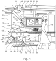
- Fig. 1 schematically shows an example of a holding arrangement 10 for an X-ray imaging device. It is noted that the holding arrangement 10 is shown in the context of an example of a medical X-ray imaging system as an option.
- the holding arrangement 10 comprises a lower source robot 12 for movably holding an X-ray source and an upper detector robot 14 for movably holding an X-ray detector.
- the upper detector robot 14 comprises an upper base 16, a first upper arm 18, a second upper arm 20 and a detector mount 22.
- the upper base 16 comprises an upper base plate 24 and an upper base mount 26 rotatably connected to the upper base plate 24.
- the upper base plate 24 is configured to be movably mounted to a ceiling support.
- the first upper arm 18 is rotatably connected to the upper base mount 26, the second upper arm 20 is rotatably connected to the first upper arm 18 and the detector mount 22 is rotatably connected to the second upper arm 20.
- the second upper arm 20 comprises two arm portions 28, 30 that are rotatably connected around a longitudinal upper arm axis 32 of the second upper arm 20.
- the second upper arm 20 is having a greater length than the first upper arm 18.
- holding arrangement relates to providing a movable mount for the X-ray source and the X-ray detector of the X-ray imaging system.
- the term "lower source robot” relates to a robot for moving and holding the X-ray source.
- the robot is mounted to the floor and the X-ray source is mounted at the free end of the robot.
- the robot may have the form of an arm with several movable joints that allow a high degree of freedom of movement.
- rotateably connected relates to a connection that allows a rotating movement around a rotation axis, e.g. a pivoting movement or a turning movement.
- the X-ray source is usually provided below a subject support like a subject table.
- the X-ray detector is arranged above the table to detect X-ray after passing through an object.
- the X-ray source and X-ray detector can be arranged such that they are moved in common around an iso-center.
- the upper detector robot thus relates to a robot holding and moving an X-ray detector for medical X-ray imaging.
- the lower detector robot relates to a robot holding and moving an X-ray source for medical X-ray imaging.
- the first upper arm 18 is rotatably connected to the upper base 16 via a first upper rotation axis
- the second upper 20 arm is rotatably connected to the first upper arm 18 via a second upper rotation axis, the first upper rotation axis and the second upper rotation axis being arranged parallel to each other in a horizontal direction.
- the detector mount is rotatably connected to the second upper arm via a third upper rotation axis, the third upper rotation axis being arranged perpendicular to the longitudinal arm axis of the second upper arm.
- the longitudinal arm axis of the second upper arm can also be referred to as longitudinal second upper arm axis.
- the proximal end of the first upper arm can also be referred to as first upper arm proximal end.
- the distal end of the first upper arm can also be referred to as first upper arm distal end.
- the proximal end of the second upper arm can also be referred to as second upper arm proximal end.
- the distal end of the second upper arm can also be referred to as second upper arm distal end.
- the length of the second upper arm is at least twice the length of the first upper arm.
- FIG. 1 shows the X-ray detector and the X-ray source mounted to the respective upper detector robot and lower source robot.
- This is referred to as the medical X-ray imaging system.
- the upper detector robot and the lower source robot without the X-ray detector and X-ray source.
- This is referred to as the holding arrangement for an X-ray imaging device, which can also be referred to as holding arrangement for a medical X-ray imaging system.
- an X-ray collimator to shape an X-ray beam generated by the X-ray source is provided in an option.
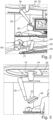
- the detector mount 22 comprises a detector mounting member 34 and a detector retainer plate 36 configured for fixedly attaching an X-ray detector 38.
- the detector retainer plate 36 is connected to the detector mounting member 34 rotatably around a detector axis 40 configured to be aligned with a center of a detector surface of the X-ray detector.
- the second upper arm 20 is connected to the detector mounting member 34 around a mounting axis 42 arranged perpendicular to the detector axis.
- the mounting axis 42 is displaced to the detector axis 40 by an offset 44 (see Fig. 4 ) that is at least a third of a diameter of the detector surface.
- the second upper arm 20 is connected to the first lower arm 18 around a horizontal axis 43.
- the mounting axis can also be referred to as detector mounting axis.
- the detector retainer plate can also be referred to as retainer plate.
- the offset is at least half of the diameter of the detector surface.
- a first linear movement of the base plate with respect to the ceiling is provided. This is a valuable addition of the robot movement-axis layout.
- the vertical upper base rotation axis is aligned with a horizontal rotation axis 48 of the rotatable connection of the first upper arm and the upper base mount.
- an offset 50 is provided between the upper vertical base rotation axis and the horizontal rotation axis of the rotatable connection of the first upper arm and the upper base mount.
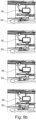
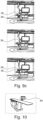
- a first positioning of the upper detector robot 14 is indicated with straight lines 49; a second positioning of the upper detector robot 14 is indicated with first broken lines 47 and a third positioning of the upper detector robot 14 is indicated with second broken lines 45.
- first positioning of the upper detector robot 14 is indicated with straight lines 49; a second positioning of the upper detector robot 14 is indicated with first broken lines 47 and a third positioning of the upper detector robot 14 is indicated with second broken lines 45.
- a first position P1 of the detector is achieved lateral to a subject 41 on a support 39.
- the support 39 is arranged in a first height H1.
- a second position P2 of the detector is achieved lateral to the subject 41 on the support 39.
- the support 39 is arranged in a second height H2.
- a third position P3 of the detector is achieved above the subject 41 on the support 39.
- a drive arrangement (not shown in detail) is provided to apply a driving force for achieving a relative translational or rotational movement of at least one of the group comprising the upper base plate, the upper base mount, the first upper arm, the second upper arm, the two arm portions, the detector mounting member and the detector retainer plate.
- the drive arrangement is provided to apply a driving force for achieving a relative rotational movement of:
- the drive arrangement is provided to apply a driving force for achieving a relative linear movement of:
- the smooth outer contour is achieved by an arm housing that also covers the portions of the rotatable connection.
- the term smooth relates to a contour free of steps, protrusions or dents.
- the upper base mount has a smooth outer contour with a decreasing outer diameter from its proximal end to its distal end.
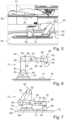
- Fig. 5 shows an example of a positioning of the lower source robot 12 of Fig. 1 .
- the subject support may be translatable in a longitudinal direction, as indicated with a third double arrow 35.
- the first lower arm 62 is rotatably connected to the lower base mount 74; the lower base plate 72 is movably connected to a floor support, e.g. on a floor support rail 75.
- the translational movement is indicated with a second double arrow 77.
- the second lower arm 64 is having a greater length than the first lower arm 62.
- the lower source robot can also be referred to as source robot, source robot arm, lower robot, lower robot arm, lower movable mount, lower mount or source mount.
- the lower source robot can also be referred to as first movable mount, first robot arm or first robot.
- the first lower arm is rotatably connected to the lower base via a first lower rotation axis
- the second lower arm is rotatably connected to the first lower arm via a second lower rotation axis, the first lower rotation axis and the second lower rotation axis being arranged parallel to each other in a horizontal direction.
- the source mount is rotatably connected to the second lower arm via a third lower rotation axis, the third lower rotation axis being arranged perpendicular to the longitudinal arm axis of the second lower arm.
- the proximal end of the first lower arm can also be referred to as first lower arm proximal end.
- the distal end of the first lower arm can also be referred to as first lower arm distal end.
- the proximal end of the second lower arm can also be referred to as second lower arm proximal end.
- the distal end of the second lower arm can also be referred to as second lower arm distal end.
- an example of the first upper arm has a length of approximately 470 mm
- an example of the first arm portion of the second upper arm has a length of approximately 400 mm
- the an example of the first arm portion of the second upper arm has a length of approximately 480 mm.
- the second lower arm is even shorter than the first lower arm.
- a combination with an offset between the base mount rotation and the first lower arm rotation is provided, thus enabling to reduce the length of the second lower arm.
- the source mount 66 comprises a source mounting member 76 and a source receiving segment 78 configured for holding an X-ray source 80.
- the source receiving segment 78 is connected to the source mounting member 76 rotatably around a source axis 82 to be aligned with a center of the X-ray source 80.
- the second lower arm 64 is connected to the source mounting member 76 around a mounting axis 84 arranged perpendicular to the source axis 82.
- the mounting axis 84 is displaced to the source axis 82 by an offset 86 (see Fig. 6 ) that is at least approximately 25% of an outer diameter of a source housing.
- an X-ray collimator is provided, but not shown in detail.
- the X-ray collimator is configured to shape an X-ray beam generated by the X-ray source.
- the X-ray source arm is rather long. For example, it is at least half of the diameter of the collimator which is placed above the X-ray source.
- the mounting axis is displaced to the source axis by an offset that is at least approximately 25% or30% of the outer diameter of the source housing, e.g. approximately 50% of the outer diameter of the source housing.
- the longitudinal arm axis 70 of the second lower arm 64, around which the two arm portions of the second lower arm 64 can be rotated is arranged with an offset 88 to the rotatable connection, i.e. the horizontal axis 87, of the first lower arm and the second lower arm.
- the offset 88 is at least half of the diameter of the outer dimension of the second lower arm at its proximal end.
- the lower base mount 74 is connected to the lower base plate 72 rotatably around a vertical lower base rotation axis 90.
- a drive arrangement is provided to apply a driving force for achieving a relative translational or rotational movement of at least one of the group comprising the lower base plate, the lower base mount, the lower upper arm, the second lower arm, the two arm portions, the source mounting member and the source receiving segment.
- the upper base is configured to be slidably mounted to an upper rail arrangement 96.
- a drive is provided to apply a driving force for achieving a sliding, i.e. translational movement of the upper base along the upper rail arrangement.
- the X-ray detector is mounted to the detector retainer plate of the detector mount.
- the X-ray source is mounted to the source receiving segment of the source mount.
- removing the C-arm from the operational room frees up a lot of space and improves patient access during the procedures.
- an additional staff member can be standing close to the patient, e.g. during more complex hybrid procedures.
- the C-arm there is basically unlimited access to the patient table and patient during the patient preparation. This helps in reducing preparation time.
- the room setup is much easier and requires less intensive planning, which is often necessary when a C-arm is present that requires the staff to prepare the intended procedure very well to plan where the C-arm will be placed and where to position the required staff and other equipment.
- the flexibility of the robotic system allows a flexible iso-center height which implies that much more physicians will be able to position the patient at the optimal ergonomic height.
- the presently provided C-less robots are also beneficial regarding building structure related aspects: Compared to C-arm solutions, a weight reduction of more than 50% and more is provided, which will enable much easier ceiling interfaces. This will save significant time and money for the hospital in view of room preparation constructions to be performed by the hospital.
- the required footprint of the solution within the operational room is much smaller, e.g. a reduction by a third up to a half which enables the hospitals to make more efficient use of their available space, or reduce the hassle to create bigger examination rooms.
- FD detector robot
- TR tube robot
- an optimized setup for the detector robot is provided by:
- an optimized setup for the X-ray source robot is provided by:
Landscapes
- Health & Medical Sciences (AREA)
- Life Sciences & Earth Sciences (AREA)
- Engineering & Computer Science (AREA)
- Medical Informatics (AREA)
- Radiology & Medical Imaging (AREA)
- Molecular Biology (AREA)
- Biophysics (AREA)
- Nuclear Medicine, Radiotherapy & Molecular Imaging (AREA)
- Optics & Photonics (AREA)
- Pathology (AREA)
- Physics & Mathematics (AREA)
- Biomedical Technology (AREA)
- Heart & Thoracic Surgery (AREA)
- High Energy & Nuclear Physics (AREA)
- Surgery (AREA)
- Animal Behavior & Ethology (AREA)
- General Health & Medical Sciences (AREA)
- Public Health (AREA)
- Veterinary Medicine (AREA)
- Automation & Control Theory (AREA)
- Robotics (AREA)
- Apparatus For Radiation Diagnosis (AREA)
Priority Applications (2)
| Application Number | Priority Date | Filing Date | Title |
|---|---|---|---|
| EP23203176.5A EP4537757A1 (de) | 2023-10-12 | 2023-10-12 | Halteanordnung für eine röntgenbildgebungsvorrichtung |
| PCT/EP2024/078330 WO2025078396A1 (en) | 2023-10-12 | 2024-10-09 | Holding arrangement for an x-ray imaging device |
Applications Claiming Priority (1)
| Application Number | Priority Date | Filing Date | Title |
|---|---|---|---|
| EP23203176.5A EP4537757A1 (de) | 2023-10-12 | 2023-10-12 | Halteanordnung für eine röntgenbildgebungsvorrichtung |
Publications (1)
| Publication Number | Publication Date |
|---|---|
| EP4537757A1 true EP4537757A1 (de) | 2025-04-16 |
Family
ID=88373885
Family Applications (1)
| Application Number | Title | Priority Date | Filing Date |
|---|---|---|---|
| EP23203176.5A Withdrawn EP4537757A1 (de) | 2023-10-12 | 2023-10-12 | Halteanordnung für eine röntgenbildgebungsvorrichtung |
Country Status (2)
| Country | Link |
|---|---|
| EP (1) | EP4537757A1 (de) |
| WO (1) | WO2025078396A1 (de) |
Citations (4)
| Publication number | Priority date | Publication date | Assignee | Title |
|---|---|---|---|---|
| US6200024B1 (en) * | 1998-11-27 | 2001-03-13 | Picker International, Inc. | Virtual C-arm robotic positioning system for use in radiographic imaging equipment |
| US20110069818A1 (en) * | 2008-03-31 | 2011-03-24 | Kuka Roboter Gmbh | X-Ray Apparatus And Medical Workstation |
| US20180242938A1 (en) * | 2015-08-17 | 2018-08-30 | Kawasaki Jukogyo Kabushiki Kaisha | X-ray imaging system |
| WO2020089272A1 (en) | 2018-10-30 | 2020-05-07 | Koninklijke Philips N.V. | X-ray imaging arrangement |
-
2023
- 2023-10-12 EP EP23203176.5A patent/EP4537757A1/de not_active Withdrawn
-
2024
- 2024-10-09 WO PCT/EP2024/078330 patent/WO2025078396A1/en active Pending
Patent Citations (5)
| Publication number | Priority date | Publication date | Assignee | Title |
|---|---|---|---|---|
| US6200024B1 (en) * | 1998-11-27 | 2001-03-13 | Picker International, Inc. | Virtual C-arm robotic positioning system for use in radiographic imaging equipment |
| US20110069818A1 (en) * | 2008-03-31 | 2011-03-24 | Kuka Roboter Gmbh | X-Ray Apparatus And Medical Workstation |
| US20180242938A1 (en) * | 2015-08-17 | 2018-08-30 | Kawasaki Jukogyo Kabushiki Kaisha | X-ray imaging system |
| WO2020089272A1 (en) | 2018-10-30 | 2020-05-07 | Koninklijke Philips N.V. | X-ray imaging arrangement |
| US20210401390A1 (en) * | 2018-10-30 | 2021-12-30 | Koninklijke Philips N.V. | X-ray imaging arrangment |
Also Published As
| Publication number | Publication date |
|---|---|
| WO2025078396A1 (en) | 2025-04-17 |
Similar Documents
| Publication | Publication Date | Title |
|---|---|---|
| EP3878392B1 (de) | Integrierte medizinische bildgebung und chirurgisches robotersystem | |
| US6200024B1 (en) | Virtual C-arm robotic positioning system for use in radiographic imaging equipment | |
| JP6449958B2 (ja) | ロボット手術台 | |
| US5515416A (en) | Bi-plane imaging device | |
| EP3342349B1 (de) | Robotischer operationstisch und hybrides betriebssystem | |
| CN113038881B (zh) | X射线成像装置 | |
| US6592259B2 (en) | Scaleable x-ray positioner | |
| WO2022060793A1 (en) | Medical imaging device and methods | |
| CN113133782A (zh) | 移动式平台和包括多个移动式平台的系统 | |
| EP2407108B1 (de) | Bewegliches Abbildungssystem mit integrierten Anzeigemitteln | |
| JPH08112272A (ja) | 2方向x線透視撮影装置 | |
| EP3787513B1 (de) | System zur durchführung von roboteroperationen | |
| EP4537757A1 (de) | Halteanordnung für eine röntgenbildgebungsvorrichtung | |
| WO2020048896A1 (en) | An x-ray imaging device | |
| JP6270957B1 (ja) | ロボット手術台 | |
| EP4360556A1 (de) | Verbessertes kabelverwaltungssystem und verfahren für c-arm-bildgebungssysteme | |
| JP5091506B2 (ja) | X線診断装置 | |
| US20250099195A1 (en) | A console system for a multi-arm robotic surgical system | |
| JP6708768B2 (ja) | ロボット手術台およびハイブリッド手術室 | |
| JP2004216193A (ja) | 2方向x線透視撮影装置 |
Legal Events
| Date | Code | Title | Description |
|---|---|---|---|
| PUAI | Public reference made under article 153(3) epc to a published international application that has entered the european phase |
Free format text: ORIGINAL CODE: 0009012 |
|
| STAA | Information on the status of an ep patent application or granted ep patent |
Free format text: STATUS: THE APPLICATION HAS BEEN PUBLISHED |
|
| AK | Designated contracting states |
Kind code of ref document: A1 Designated state(s): AL AT BE BG CH CY CZ DE DK EE ES FI FR GB GR HR HU IE IS IT LI LT LU LV MC ME MK MT NL NO PL PT RO RS SE SI SK SM TR |
|
| STAA | Information on the status of an ep patent application or granted ep patent |
Free format text: STATUS: THE APPLICATION IS DEEMED TO BE WITHDRAWN |
|
| 18D | Application deemed to be withdrawn |
Effective date: 20251017 |