EP4537760A1 - Appareil de détermination de position de patient pour un système d'imagerie médicale - Google Patents
Appareil de détermination de position de patient pour un système d'imagerie médicale Download PDFInfo
- Publication number
- EP4537760A1 EP4537760A1 EP23203464.5A EP23203464A EP4537760A1 EP 4537760 A1 EP4537760 A1 EP 4537760A1 EP 23203464 A EP23203464 A EP 23203464A EP 4537760 A1 EP4537760 A1 EP 4537760A1
- Authority
- EP
- European Patent Office
- Prior art keywords
- medical imaging
- imaging system
- position determination
- intersection point
- determination apparatus
- Prior art date
- Legal status (The legal status is an assumption and is not a legal conclusion. Google has not performed a legal analysis and makes no representation as to the accuracy of the status listed.)
- Withdrawn
Links
Images


Classifications
-
- A—HUMAN NECESSITIES
- A61—MEDICAL OR VETERINARY SCIENCE; HYGIENE
- A61B—DIAGNOSIS; SURGERY; IDENTIFICATION
- A61B6/00—Apparatus or devices for radiation diagnosis; Apparatus or devices for radiation diagnosis combined with radiation therapy equipment
- A61B6/08—Auxiliary means for directing the radiation beam to a particular spot, e.g. using light beams
-
- A—HUMAN NECESSITIES
- A61—MEDICAL OR VETERINARY SCIENCE; HYGIENE
- A61B—DIAGNOSIS; SURGERY; IDENTIFICATION
- A61B6/00—Apparatus or devices for radiation diagnosis; Apparatus or devices for radiation diagnosis combined with radiation therapy equipment
- A61B6/44—Constructional features of apparatus for radiation diagnosis
- A61B6/4476—Constructional features of apparatus for radiation diagnosis related to motor-assisted motion of the source unit
-
- A—HUMAN NECESSITIES
- A61—MEDICAL OR VETERINARY SCIENCE; HYGIENE
- A61B—DIAGNOSIS; SURGERY; IDENTIFICATION
- A61B6/00—Apparatus or devices for radiation diagnosis; Apparatus or devices for radiation diagnosis combined with radiation therapy equipment
- A61B6/58—Testing, adjusting or calibrating thereof
- A61B6/589—Setting distance between source unit and patient
Definitions
- the invention relates to a patient position determination apparatus for a medical imaging system, to a medical imaging system comprising the patient position determination apparatus, and to a method for determining patient position during medical imaging using the said apparatus.
- a 3D camera is mounted in or near the collimator of an X-ray tube to obtain patient position information to support positioning or to detect motion or breathing of the patient. Nonetheless, opportunities exist to provide improved information on patient position to the radiographer, leading to better patient positioning and consequently to fewer disruptions to the workflow.
- a patient position determination apparatus for a medical imaging system.
- the patient position determination apparatus comprises: an adjustable mount for an image capture device; at least one actuator configured to move the adjustable mount; and a controller configured to locate, based on configuration data relating to a setup of the medical imaging system, an intersection point at which an imaging beam of the medical imaging system intersects a surface in a region to be imaged, and to control the at least one actuator to move the adjustable mount to position a field of view of the image capture device relative to the intersection point.
- the apparatus enables proper synchronization between the positioning image captured by the image capture device and the medical image captured by the medical imaging system, in particular by improving the centricity of the positioning image at multiple source-to-image distances, thereby providing improved information on patient position to the radiographer with consequent rationalization of the workflow.
- the controller is further configured to control the at least one actuator to move the adjustable mount so that the field of view satisfies a predetermined relationship with the intersection point.
- the predetermined relationship is satisfied when a center of the field of view coincides with the intersection point, for example by appearing at the same location (within a predetermined tolerance, for example a user-dependent tolerance set according to the preferences of a particular user or typical user).
- the intersection point may correspond for example to the center of the X-ray image to acquire, to the center of a detector of the medical imaging system, to the center of a collimated area, or to the center of the object to be examined (e.g., anatomy).
- the intersection point is a point at which the imaging beam intersects a source-facing surface of the detector of the medical imaging system, and the controller is configured to locate the intersection point based on the configuration data comprising one or more of: i) a position of a focal spot of the medical imaging system; ii) a direction of the imaging beam; iii) a position of a center of the detector of the medical imaging system.
- the intersection point is a point at which the imaging beam intersects an object to be examined, and the controller is configured to locate the intersection point based further on the configuration data comprising depth information acquired by the image capture device (comprising for example a 3D camera).
- the configuration data relating to the imaging setup may be known in advance or may be obtained using a sensor arrangement.
- Configuration data describing fixed geometry parameters of the medical imaging system may be known in advance.
- Configuration data describing variable geometry parameters of the medical imaging system may be obtained via sensors (e.g. linear position sensors and angulation sensors).
- Configuration data describing depth information may be acquired by the image capture device comprising for example a 3D camera.
- the controller is configured to determine the direction of the central beam, the position of the focal spot, and the position of the center of the detector center. Based on the position of the center of the image capture device relative to the position of the focal spot, the controller is configured to calculate at least one tilt angle based on which the controller controls the at least one actuator to move the adjustable mount.
- the at least one actuator is configured to tilt the adjustable mount around a single axis. In another example, the at least one actuator is configured to tilt the adjustable mount around multiple axes, for example two perpendicular axes. In other examples, the at least one actuator may be further configured to effect linear translation of the adjustable mount.
- the patient position determination apparatus may be manufactured and sold as comprising the image capture device or that the image capture device may be provided as an aftermarket product to be installed into the patient position determination apparatus.
- the image capture device may comprise a sensor configured to acquire 3D data of the object to be examined, for example depth information that is usable to calculate the intersection point in the presence of the object.
- the image capture device comprises a 3D camera.
- the image capture device may be configured to obtain patient position information to support patient positioning or to detect motion or breathing of the patient.
- the patient position determination apparatus may be mountable in or near a collimator of an X-ray tube, for example.
- a medical imaging system comprising the patient position determination apparatus of the first aspect.
- an X-ray apparatus or tube, or a collimator therefor, comprising the patient position determination apparatus of the first aspect.
- a computer-implemented method for determining patient position during medical imaging using the apparatus of the first aspect comprises: locating, based on the configuration data relating to the setup of the medical imaging system, the intersection point at which the imaging beam of the medical imaging system intersects the surface in the region to be imaged; controlling the at least one actuator to move the adjustable mount to position the field of view of the image capture device relative to the intersection point; and controlling the so-positioned image capture device to acquire an image of a patient to be examined for use in patient positioning.
- a computing system configured to perform the method of the third aspect.
- a computer program comprising instructions which, when executed by a computing system, enable or cause the computing system to perform the method of the third aspect.
- a computer-readable (storage) medium comprising instructions which, when executed by a computing system, enable or cause the computing system to perform the method of the third aspect.
- the computer-readable medium may be transitory or non-transitory, volatile or non-volatile.
- patient positioning is meant the act of placing the patient into a particular position or pose
- patient position determination refers to the act of determining the position or pose of the patient, or at least part of the patient, such as a particular anatomy to be examined, for example for the purposes of patient positioning.
- object to be examined refers to the patient or part of the patient.
- the "imaging beam” may comprise any X-ray beam capable of generating an X-ray image but in one example comprises the central beam emitted from the X-ray tube.
- the "medical imaging system” as described herein may be a radiographic imaging system such as a (digital) X-ray system (e.g., DXR), a (digital) fluoroscopy system, or any other X-ray system which provides sufficient information on its geometry parameters to implement the control of the adjustable mount, as described herein.
- the medical imaging system may utilize multiple imaging modalities.
- obtaining may comprise, for example, receiving from another system, device, or process; receiving via an interaction with a user; loading or retrieving from storage or memory; measuring or capturing using sensors or other data acquisition devices.
- determining encompasses a wide variety of actions, and may comprise, for example, calculating, computing, processing, deriving, investigating, looking up (e.g., looking up in a table, a database or another data structure), ascertaining, and the like. Also, “determining” may comprise receiving (e.g., receiving information), accessing (e.g., accessing data in a memory), and the like. Also, “determining” may comprise resolving, selecting, choosing, establishing and the like.
- phrases “one or more of A, B and C”, “at least one of A, B, and C”, and “A, B and/or C” as used herein are intended to mean all possible permutations of one or more of the listed items. That is, the phrase “A and/or B” means (A), (B), or (A and B), while the phrase “A, B, and/or C” means (A), (B), (C), (A and B), (A and C), (B and C), or (A, B, and C).
- the invention may include one or more aspects, examples or features in isolation or combination whether specifically disclosed in that combination or in isolation. Any optional feature or sub-aspect of one of the above aspects applies as appropriate to any of the other aspects.
- Figs. 1A-C i llustrate a medical imaging system 100 comprising an X-ray tube 102 with collimator positioned facing a detector 104.
- the tube 102 has a region of X-ray (ROX) 106 comprising a central imaging beam or center 108.
- a fixed camera 110 mounted within the collimator is positioned to view the detector 104 for providing images for use in patient positioning.
- the fixed camera 110 has a field of view (FOV) 112 with a center of both the FOV 112 and the resulting image being indicated at 114.
- FOV field of view
- the FOV center 114 coincides with the ROX center 108 only for one source-to-image distance (SID), which is the situation illustrated in Fig. 1A .
- SID source-to-image distance
- the FOV center 114 deviates from the ROX center 108, which can be misleading for the radiographer, who expects the FOV center 114 to be at or near the ROX center 108 during visual quality checks.
- the anatomy to be imaged does not reside completely within the FOV 112 of the camera 110.
- Figs. 2A-C illustrate a medical imaging system 200 according to the present disclosure.
- the camera 110 is tilted in such a way that the FOV center 114 coincides with the ROX center 108 at each of multiple SIDs.
- Figs. 2B and 2C show how tilting to the right for small SIDs and to the left for large SIDs ensures that the ROX center 108 (i.e., the point at which the central X-ray beam 108 intersects the source-facing surface of the detector 104) is shown at the FOV center 114.
- Figs. 3A-C illustrate a medical imaging system 200 of Figs. 2A-C in the case that the object to be examined 300 is present.
- the camera 110 is tilted using the motorized tiltable mounting such that the FOV center 114 coincides with the ROX center 108 (i.e., the point at which the central X-ray beam 108 intersects the source-facing surface of the object to be examined 300) at each of multiple SIDs.
- Fig. 4 illustrates one non-limiting example of a patient position determination apparatus 400.
- the patient position determination apparatus 400 comprises an adjustable (i.e., tiltable) mount 402 for the camera 110 and an actuator 404 configured to move the adjustable mount 402.
- the actuator 404 comprises a rotary servomotor 406 coupled to the tiltable mount 402 via a crank mechanism 408.
- a controller 410 is provided to control the actuator 404 so as to tilt the camera 110 in the manner described with reference to Figs. 2 and 3 .
- the controller 410 is configured to obtain configuration data relating to a setup of the medical imaging system 200 and to locate, based thereon, the point at which the central imaging beam 108 intersects a source-facing surface of either the detector 104 or the object to be examined 300.
- the controller 410 then controls actuator 404 to move the tiltable mount 402 to position the FOV 112 of the camera 110 relative to the located intersection point.
- the controller 410 obtains from the medical imaging system 200 configuration data from which the position of the focal spot of the X-ray tube 102, the direction of the central X-ray beam 108, and the position of the detector 104 can be derived.
- the position of the camera sensor center relative to the position of the focal spot of the X-ray tube 102 is furthermore known to the controller 410.
- the controller 410 calculates a tilt angle for the tiltable mount 402 which places the intersection point at the FOV center 114.
- depth information obtained from the camera 110 is used by the controller 410 to calculate the intersection point at which the central X-ray beam 108 hits the object 300.
- the controller 410 calculates a tilt angle which places this intersection point at the FOV center 114.
- Fig. 5 illustrates calculation of the tilt angle for the tiltable camera 110 by the controller 410.
- the origin of the cartesian coordinate system is positioned at the center of the X-ray detector 104.
- the detector 104 lies within the y-z plane of the coordinate system.
- the focal spot 116 of the X-ray tube 102 is positioned at the coordinate (SID, 0, 0) and the central beam 108 of the tube 102 travels from the focal spot 116 to the center of the detector 104.
- the center of sensor 118 has a fixed offset (-dx, dy, dz) relative to the focal spot 116.
- the center of the camera sensor 118 is at the position (SID - dx, dy, dz).
- the camera 110 is tilted by 90° - ⁇ downwards and ⁇ to the left when looking from the focal spot 116 to the detector 104.
- the center of the detector 104 is mapped onto the center of the camera sensor 118.
- this non-limiting example of tilt angle calculation can be extended to cover more complex situations in which the tube 102 is angulated and/or in which the central beam 108 does not hit the center of the detector 104.
- the servomotor as described herein may be replaced or supplemented by an arrangement using a piezo element or a piezo stack as active component.
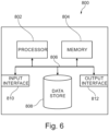
- Fig. 6 illustrates an exemplary computing system 800 that can be used to implement the controller 410 as described herein.
- the computing system 800 may form part of or comprise any desktop, laptop, server, or cloud-based computing system.
- the computing system 800 includes at least one processor 802 that executes instructions that are stored in a memory 804.
- the instructions may be, for instance, instructions for implementing functionality described as being carried out by the controller 410 or instructions for implementing one or more of the methods described herein.
- the processor 802 may access the memory 804 by way of a system bus 806.
- the memory 804 may also store conversational inputs, scores assigned to the conversational inputs, etc.
- the computing system 800 additionally includes a data store 808 that is accessible by the processor 802 by way of the system bus 806.
- the data store 808 may include executable instructions, log data, etc.
- the computing system 800 also includes an input interface 810 that allows external devices to communicate with the computing system 800. For instance, the input interface 810 may be used to receive instructions from an external computer device, from a user, etc.
- the computing system 800 also includes an output interface 812 that interfaces the computing system 800 with one or more external devices. For example, the computing system 800 may display text, images, etc. by way of the output interface 812.
- the external devices that communicate with the computing system 800 via the input interface 810 and the output interface 812 can be included in an environment that provides substantially any type of user interface with which a user can interact.
- user interface types include graphical user interfaces, natural user interfaces, and so forth.
- a graphical user interface may accept input from a user employing input device(s) such as a keyboard, mouse, remote control, or the like and provide output on an output device such as a display.
- a natural user interface may enable a user to interact with the computing system 800 in a manner free from constraints imposed by input device such as keyboards, mice, remote controls, and the like. Rather, a natural user interface can rely on speech recognition, touch and stylus recognition, gesture recognition both on screen and adjacent to the screen, air gestures, head and eye tracking, voice and speech, vision, touch, gestures, machine intelligence, and so forth.
- computing system 800 may be a distributed system. Thus, for instance, several devices may be in communication by way of a network connection and may collectively perform tasks described as being performed by the computing system 800.
- Computer-readable media include computer-readable storage media.
- Computer-readable storage media can be any available storage media that can be accessed by a computer.
- such computer-readable storage media can comprise FLASH storage media, RAM, ROM, EEPROM, CD-ROM or other optical disc storage, magnetic disk storage or other magnetic storage devices, or any other medium that can be used to carry or store desired program code in the form of instructions or data structures and that can be accessed by a computer.
- Disk and disc include compact disc (CD), laser disc, optical disc, digital versatile disc (DVD), floppy disk, and Blu-ray disc (BD), where disks usually reproduce data magnetically and discs usually reproduce data optically with lasers.
- BD Blu-ray disc
- Computer-readable media also includes communication media including any medium that facilitates transfer of a computer program from one place to another.
- a connection for instance, can be a communication medium.
- the software is transmitted from a website, server, or other remote source using a coaxial cable, fiber optic cable, twisted pair, digital subscriber line (DSL), or wireless technologies such as infrared, radio, and microwave
- coaxial cable, fiber optic cable, twisted pair, DSL, or wireless technologies such as infrared, radio and microwave
- the coaxial cable, fiber optic cable, twisted pair, DSL, or wireless technologies such as infrared, radio and microwave
- the functionally described herein can be performed, at least in part, by one or more hardware logic components.
- illustrative types of hardware logic components include Field-programmable Gate Arrays (FPGAs), Application-specific Integrated Circuits (ASICs), Application-specific Standard Products (ASSPs), System-on-a-chip systems (SOCs), Complex Programmable Logic Devices (CPLDs), etc.
Landscapes
- Health & Medical Sciences (AREA)
- Life Sciences & Earth Sciences (AREA)
- Medical Informatics (AREA)
- Engineering & Computer Science (AREA)
- Radiology & Medical Imaging (AREA)
- Biomedical Technology (AREA)
- Biophysics (AREA)
- Nuclear Medicine, Radiotherapy & Molecular Imaging (AREA)
- Optics & Photonics (AREA)
- Pathology (AREA)
- Physics & Mathematics (AREA)
- High Energy & Nuclear Physics (AREA)
- Heart & Thoracic Surgery (AREA)
- Molecular Biology (AREA)
- Surgery (AREA)
- Animal Behavior & Ethology (AREA)
- General Health & Medical Sciences (AREA)
- Public Health (AREA)
- Veterinary Medicine (AREA)
- Apparatus For Radiation Diagnosis (AREA)
Priority Applications (2)
| Application Number | Priority Date | Filing Date | Title |
|---|---|---|---|
| EP23203464.5A EP4537760A1 (fr) | 2023-10-13 | 2023-10-13 | Appareil de détermination de position de patient pour un système d'imagerie médicale |
| PCT/EP2024/076671 WO2025078143A1 (fr) | 2023-10-13 | 2024-09-23 | Appareil de détermination de position de patient pour un système d'imagerie médicale |
Applications Claiming Priority (1)
| Application Number | Priority Date | Filing Date | Title |
|---|---|---|---|
| EP23203464.5A EP4537760A1 (fr) | 2023-10-13 | 2023-10-13 | Appareil de détermination de position de patient pour un système d'imagerie médicale |
Publications (1)
| Publication Number | Publication Date |
|---|---|
| EP4537760A1 true EP4537760A1 (fr) | 2025-04-16 |
Family
ID=88412359
Family Applications (1)
| Application Number | Title | Priority Date | Filing Date |
|---|---|---|---|
| EP23203464.5A Withdrawn EP4537760A1 (fr) | 2023-10-13 | 2023-10-13 | Appareil de détermination de position de patient pour un système d'imagerie médicale |
Country Status (2)
| Country | Link |
|---|---|
| EP (1) | EP4537760A1 (fr) |
| WO (1) | WO2025078143A1 (fr) |
Citations (3)
| Publication number | Priority date | Publication date | Assignee | Title |
|---|---|---|---|---|
| US5159622A (en) * | 1989-11-17 | 1992-10-27 | Kabushiki Kaisha Toshiba | X-ray fluoroscopic imaging apparatus with extended imaging set up range |
| US20080122936A1 (en) * | 2006-11-23 | 2008-05-29 | Stephen Johnson Lomnes | System and method for imaging |
| US20190328465A1 (en) * | 2018-04-30 | 2019-10-31 | Aih Llc | System and method for real image view and tracking guided positioning for a mobile radiology or medical device |
-
2023
- 2023-10-13 EP EP23203464.5A patent/EP4537760A1/fr not_active Withdrawn
-
2024
- 2024-09-23 WO PCT/EP2024/076671 patent/WO2025078143A1/fr active Pending
Patent Citations (3)
| Publication number | Priority date | Publication date | Assignee | Title |
|---|---|---|---|---|
| US5159622A (en) * | 1989-11-17 | 1992-10-27 | Kabushiki Kaisha Toshiba | X-ray fluoroscopic imaging apparatus with extended imaging set up range |
| US20080122936A1 (en) * | 2006-11-23 | 2008-05-29 | Stephen Johnson Lomnes | System and method for imaging |
| US20190328465A1 (en) * | 2018-04-30 | 2019-10-31 | Aih Llc | System and method for real image view and tracking guided positioning for a mobile radiology or medical device |
Also Published As
| Publication number | Publication date |
|---|---|
| WO2025078143A9 (fr) | 2026-04-30 |
| WO2025078143A1 (fr) | 2025-04-17 |
Similar Documents
| Publication | Publication Date | Title |
|---|---|---|
| US6359960B1 (en) | Method for identifying and locating markers in a 3D volume data set | |
| JP6579181B2 (ja) | 画像取得装置 | |
| US7538744B1 (en) | Method and apparatus for computer-aided determination of viewer's gaze direction | |
| US9943271B2 (en) | Method and control system for controlling a medical device | |
| US11161248B2 (en) | Automatic robotic arm calibration to camera system using a laser | |
| JP4649319B2 (ja) | 視線検出装置、視線検出方法、および視線検出プログラム | |
| US20150332465A1 (en) | Method and system for medical tracking using a plurality of camera positions | |
| RU2012117621A (ru) | Углы наблюдения автоматической с-дуги для лечения системных сердечных заболеваний | |
| CN105581807A (zh) | 用于基于模型的定位的断层成像设备以及方法和计算机程序 | |
| US20200051280A1 (en) | Method for calibrating objects in a reference coordinate system and method for tracking objects | |
| EP3595533B1 (fr) | Détermination d'un signal de guidage et système de fourniture de guidage pour un transducteur portatif à ultrasons | |
| JP2021010650A (ja) | 動体追跡装置および放射線治療システム、ならびに動体の追跡方法 | |
| US12263031B2 (en) | Determining a configuration of a medical x-ray imaging system for detecting a marker device | |
| EP4537760A1 (fr) | Appareil de détermination de position de patient pour un système d'imagerie médicale | |
| CN112869701B (zh) | 视线检测方法、手术机器人系统、控制方法和存储介质 | |
| US20020109071A1 (en) | Method and apparatus for automatic focusing of an optical device | |
| JP6792025B2 (ja) | Octシステム、oct映像生成方法及び格納媒体 | |
| Hartov et al. | Adaptive spatial calibration of a 3D ultrasound system | |
| US20150327824A1 (en) | Method, apparatus and x-ray recording system for visualization of an x-ray region | |
| EP3457353B1 (fr) | Procédé et système pour l'obtention de forme réelle d'objets dans une image médicale | |
| CN116350359A (zh) | 引导影像设备的位置调整的方法、存储介质及医疗系统 | |
| CN118476820A (zh) | 预览图像生成方法和装置、设备、介质及产品 | |
| EP4086839A1 (fr) | Piquage d'images multiples pour créer une image panoramique | |
| JP2001338278A (ja) | 形状測定装置 | |
| JP2010071867A (ja) | 偏心測定装置および方法 |
Legal Events
| Date | Code | Title | Description |
|---|---|---|---|
| PUAI | Public reference made under article 153(3) epc to a published international application that has entered the european phase |
Free format text: ORIGINAL CODE: 0009012 |
|
| STAA | Information on the status of an ep patent application or granted ep patent |
Free format text: STATUS: THE APPLICATION HAS BEEN PUBLISHED |
|
| AK | Designated contracting states |
Kind code of ref document: A1 Designated state(s): AL AT BE BG CH CY CZ DE DK EE ES FI FR GB GR HR HU IE IS IT LI LT LU LV MC ME MK MT NL NO PL PT RO RS SE SI SK SM TR |
|
| STAA | Information on the status of an ep patent application or granted ep patent |
Free format text: STATUS: THE APPLICATION IS DEEMED TO BE WITHDRAWN |
|
| 18D | Application deemed to be withdrawn |
Effective date: 20251017 |