EP4537791A2 - Schall- und vibrationssensoren zur schätzung des durchmessers einer klappenprothese während der expansion - Google Patents
Schall- und vibrationssensoren zur schätzung des durchmessers einer klappenprothese während der expansion Download PDFInfo
- Publication number
- EP4537791A2 EP4537791A2 EP24206617.3A EP24206617A EP4537791A2 EP 4537791 A2 EP4537791 A2 EP 4537791A2 EP 24206617 A EP24206617 A EP 24206617A EP 4537791 A2 EP4537791 A2 EP 4537791A2
- Authority
- EP
- European Patent Office
- Prior art keywords
- expansion
- sound sensor
- examples
- prosthetic valve
- sleeve
- Prior art date
- Legal status (The legal status is an assumption and is not a legal conclusion. Google has not performed a legal analysis and makes no representation as to the accuracy of the status listed.)
- Pending
Links
Images







Classifications
-
- A—HUMAN NECESSITIES
- A61—MEDICAL OR VETERINARY SCIENCE; HYGIENE
- A61F—FILTERS IMPLANTABLE INTO BLOOD VESSELS; PROSTHESES; DEVICES PROVIDING PATENCY TO, OR PREVENTING COLLAPSING OF, TUBULAR STRUCTURES OF THE BODY, e.g. STENTS; ORTHOPAEDIC, NURSING OR CONTRACEPTIVE DEVICES; FOMENTATION; TREATMENT OR PROTECTION OF EYES OR EARS; BANDAGES, DRESSINGS OR ABSORBENT PADS; FIRST-AID KITS
- A61F2/00—Filters implantable into blood vessels; Prostheses, i.e. artificial substitutes or replacements for parts of the body; Appliances for connecting them with the body; Devices providing patency to, or preventing collapsing of, tubular structures of the body, e.g. stents
- A61F2/02—Prostheses implantable into the body
- A61F2/24—Heart valves ; Vascular valves, e.g. venous valves; Heart implants, e.g. passive devices for improving the function of the native valve or the heart muscle; Transmyocardial revascularisation [TMR] devices; Valves implantable in the body
- A61F2/2412—Heart valves ; Vascular valves, e.g. venous valves; Heart implants, e.g. passive devices for improving the function of the native valve or the heart muscle; Transmyocardial revascularisation [TMR] devices; Valves implantable in the body with soft flexible valve members, e.g. tissue valves shaped like natural valves
- A61F2/2418—Scaffolds therefor, e.g. support stents
-
- A—HUMAN NECESSITIES
- A61—MEDICAL OR VETERINARY SCIENCE; HYGIENE
- A61F—FILTERS IMPLANTABLE INTO BLOOD VESSELS; PROSTHESES; DEVICES PROVIDING PATENCY TO, OR PREVENTING COLLAPSING OF, TUBULAR STRUCTURES OF THE BODY, e.g. STENTS; ORTHOPAEDIC, NURSING OR CONTRACEPTIVE DEVICES; FOMENTATION; TREATMENT OR PROTECTION OF EYES OR EARS; BANDAGES, DRESSINGS OR ABSORBENT PADS; FIRST-AID KITS
- A61F2/00—Filters implantable into blood vessels; Prostheses, i.e. artificial substitutes or replacements for parts of the body; Appliances for connecting them with the body; Devices providing patency to, or preventing collapsing of, tubular structures of the body, e.g. stents
- A61F2/02—Prostheses implantable into the body
- A61F2/24—Heart valves ; Vascular valves, e.g. venous valves; Heart implants, e.g. passive devices for improving the function of the native valve or the heart muscle; Transmyocardial revascularisation [TMR] devices; Valves implantable in the body
-
- A—HUMAN NECESSITIES
- A61—MEDICAL OR VETERINARY SCIENCE; HYGIENE
- A61F—FILTERS IMPLANTABLE INTO BLOOD VESSELS; PROSTHESES; DEVICES PROVIDING PATENCY TO, OR PREVENTING COLLAPSING OF, TUBULAR STRUCTURES OF THE BODY, e.g. STENTS; ORTHOPAEDIC, NURSING OR CONTRACEPTIVE DEVICES; FOMENTATION; TREATMENT OR PROTECTION OF EYES OR EARS; BANDAGES, DRESSINGS OR ABSORBENT PADS; FIRST-AID KITS
- A61F2/00—Filters implantable into blood vessels; Prostheses, i.e. artificial substitutes or replacements for parts of the body; Appliances for connecting them with the body; Devices providing patency to, or preventing collapsing of, tubular structures of the body, e.g. stents
- A61F2/02—Prostheses implantable into the body
- A61F2/24—Heart valves ; Vascular valves, e.g. venous valves; Heart implants, e.g. passive devices for improving the function of the native valve or the heart muscle; Transmyocardial revascularisation [TMR] devices; Valves implantable in the body
- A61F2/2427—Devices for manipulating or deploying heart valves during implantation
- A61F2/243—Deployment by mechanical expansion
-
- A—HUMAN NECESSITIES
- A61—MEDICAL OR VETERINARY SCIENCE; HYGIENE
- A61F—FILTERS IMPLANTABLE INTO BLOOD VESSELS; PROSTHESES; DEVICES PROVIDING PATENCY TO, OR PREVENTING COLLAPSING OF, TUBULAR STRUCTURES OF THE BODY, e.g. STENTS; ORTHOPAEDIC, NURSING OR CONTRACEPTIVE DEVICES; FOMENTATION; TREATMENT OR PROTECTION OF EYES OR EARS; BANDAGES, DRESSINGS OR ABSORBENT PADS; FIRST-AID KITS
- A61F2/00—Filters implantable into blood vessels; Prostheses, i.e. artificial substitutes or replacements for parts of the body; Appliances for connecting them with the body; Devices providing patency to, or preventing collapsing of, tubular structures of the body, e.g. stents
- A61F2/95—Instruments specially adapted for placement or removal of stents or stent-grafts
- A61F2/9517—Instruments specially adapted for placement or removal of stents or stent-grafts handle assemblies therefor
-
- A—HUMAN NECESSITIES
- A61—MEDICAL OR VETERINARY SCIENCE; HYGIENE
- A61F—FILTERS IMPLANTABLE INTO BLOOD VESSELS; PROSTHESES; DEVICES PROVIDING PATENCY TO, OR PREVENTING COLLAPSING OF, TUBULAR STRUCTURES OF THE BODY, e.g. STENTS; ORTHOPAEDIC, NURSING OR CONTRACEPTIVE DEVICES; FOMENTATION; TREATMENT OR PROTECTION OF EYES OR EARS; BANDAGES, DRESSINGS OR ABSORBENT PADS; FIRST-AID KITS
- A61F2220/00—Fixations or connections for prostheses classified in groups A61F2/00 - A61F2/26 or A61F2/82 or A61F9/00 or A61F11/00 or subgroups thereof
- A61F2220/0025—Connections or couplings between prosthetic parts, e.g. between modular parts; Connecting elements
-
- A—HUMAN NECESSITIES
- A61—MEDICAL OR VETERINARY SCIENCE; HYGIENE
- A61F—FILTERS IMPLANTABLE INTO BLOOD VESSELS; PROSTHESES; DEVICES PROVIDING PATENCY TO, OR PREVENTING COLLAPSING OF, TUBULAR STRUCTURES OF THE BODY, e.g. STENTS; ORTHOPAEDIC, NURSING OR CONTRACEPTIVE DEVICES; FOMENTATION; TREATMENT OR PROTECTION OF EYES OR EARS; BANDAGES, DRESSINGS OR ABSORBENT PADS; FIRST-AID KITS
- A61F2220/00—Fixations or connections for prostheses classified in groups A61F2/00 - A61F2/26 or A61F2/82 or A61F9/00 or A61F11/00 or subgroups thereof
- A61F2220/0025—Connections or couplings between prosthetic parts, e.g. between modular parts; Connecting elements
- A61F2220/0041—Connections or couplings between prosthetic parts, e.g. between modular parts; Connecting elements using additional screws, bolts, dowels or rivets, e.g. connecting screws
-
- A—HUMAN NECESSITIES
- A61—MEDICAL OR VETERINARY SCIENCE; HYGIENE
- A61F—FILTERS IMPLANTABLE INTO BLOOD VESSELS; PROSTHESES; DEVICES PROVIDING PATENCY TO, OR PREVENTING COLLAPSING OF, TUBULAR STRUCTURES OF THE BODY, e.g. STENTS; ORTHOPAEDIC, NURSING OR CONTRACEPTIVE DEVICES; FOMENTATION; TREATMENT OR PROTECTION OF EYES OR EARS; BANDAGES, DRESSINGS OR ABSORBENT PADS; FIRST-AID KITS
- A61F2220/00—Fixations or connections for prostheses classified in groups A61F2/00 - A61F2/26 or A61F2/82 or A61F9/00 or A61F11/00 or subgroups thereof
- A61F2220/0025—Connections or couplings between prosthetic parts, e.g. between modular parts; Connecting elements
- A61F2220/0091—Connections or couplings between prosthetic parts, e.g. between modular parts; Connecting elements connected by a hinged linkage mechanism, e.g. of the single-bar or multi-bar linkage type
-
- A—HUMAN NECESSITIES
- A61—MEDICAL OR VETERINARY SCIENCE; HYGIENE
- A61F—FILTERS IMPLANTABLE INTO BLOOD VESSELS; PROSTHESES; DEVICES PROVIDING PATENCY TO, OR PREVENTING COLLAPSING OF, TUBULAR STRUCTURES OF THE BODY, e.g. STENTS; ORTHOPAEDIC, NURSING OR CONTRACEPTIVE DEVICES; FOMENTATION; TREATMENT OR PROTECTION OF EYES OR EARS; BANDAGES, DRESSINGS OR ABSORBENT PADS; FIRST-AID KITS
- A61F2250/00—Special features of prostheses classified in groups A61F2/00 - A61F2/26 or A61F2/82 or A61F9/00 or A61F11/00 or subgroups thereof
- A61F2250/0004—Special features of prostheses classified in groups A61F2/00 - A61F2/26 or A61F2/82 or A61F9/00 or A61F11/00 or subgroups thereof adjustable
- A61F2250/001—Special features of prostheses classified in groups A61F2/00 - A61F2/26 or A61F2/82 or A61F9/00 or A61F11/00 or subgroups thereof adjustable for adjusting a diameter
-
- A—HUMAN NECESSITIES
- A61—MEDICAL OR VETERINARY SCIENCE; HYGIENE
- A61F—FILTERS IMPLANTABLE INTO BLOOD VESSELS; PROSTHESES; DEVICES PROVIDING PATENCY TO, OR PREVENTING COLLAPSING OF, TUBULAR STRUCTURES OF THE BODY, e.g. STENTS; ORTHOPAEDIC, NURSING OR CONTRACEPTIVE DEVICES; FOMENTATION; TREATMENT OR PROTECTION OF EYES OR EARS; BANDAGES, DRESSINGS OR ABSORBENT PADS; FIRST-AID KITS
- A61F2250/00—Special features of prostheses classified in groups A61F2/00 - A61F2/26 or A61F2/82 or A61F9/00 or A61F11/00 or subgroups thereof
- A61F2250/0058—Additional features; Implant or prostheses properties not otherwise provided for
- A61F2250/0096—Markers and sensors for detecting a position or changes of a position of an implant, e.g. RF sensors, ultrasound markers
Definitions
- the present invention relates to systems, assemblies and methods for estimating prosthetic valve expansion diameter, and in particular, for system and assemblies equipped with at least one sound or vibration sensor configured to provide real-time estimate of prosthetic valve expansion diameter.
- Native heart valves such as the aortic, pulmonary and mitral valves, function to assure adequate directional flow from and to the heart, and between the heart's chambers, to supply blood to the whole cardiovascular system.
- Various valvular diseases can render the valves ineffective and require replacement with artificial valves.
- Surgical procedures can be performed to repair or replace a heart valve.
- Surgeries are prone to an abundance of clinical complications, hence alternative less invasive techniques of delivering a prosthetic heart valve over a catheter and implanting it over the native malfunctioning valve, have been developed over the years.
- Mechanically expandable valves are a category of prosthetic valves that rely on a mechanical actuation mechanism for expansion.
- the actuation mechanism usually includes a plurality of actuation/locking assemblies, releasably connected to respective actuation members of the valve delivery system, controlled via the handle for actuating the assemblies to expand the valve to a desired diameter.
- the assemblies may optionally lock the valve's position to prevent undesired recompression thereof, and disconnection of the delivery system's actuation member from the valve actuation/locking assemblies, to enable retrieval thereof once the valve is properly positioned at the desired site of implantation.
- a prosthetic valve such as a mechanically expandable valve
- the diameter of the prosthetic valve should be monitored in real-time during the implantation procedure.
- the delivery assembly 100 can be utilized, for example, to deliver a prosthetic aortic valve for mounting against the aortic annulus, to deliver a prosthetic mitral valve for mounting against the mitral annulus, or to deliver a prosthetic valve for mounting against any other native annulus.
- the nosecone 109 can be connected to the distal end of the nosecone shaft 108.
- a guidewire (not shown) can extend through a central lumen of the nosecone shaft 108 and an inner lumen of the nosecone 109, so that the delivery apparatus 102 can be advanced over the guidewire through the patient's vasculature.
- the proximal ends of the nosecone shaft 108, the delivery shaft 106, components of the actuation assemblies 170, and when present - the outer shaft 104, can be coupled to the handle 110.
- the handle 110 can be maneuvered by an operator (e.g., a clinician or a surgeon) to axially advance or retract components of the delivery apparatus 102, such as the nosecone shaft 108, the delivery shaft 106, and/or the outer shaft 104, through the patient's vasculature, as well as to expand or contract the prosthetic valve 114, for example by maneuvering the actuation assemblies 170, and to disconnect the prosthetic valve 114 from the delivery apparatus 102, for example - by decoupling the actuators 172 from the expansion and locking assemblies 138 of the valve 114, in order to retract it once the prosthetic valve is mounted in the implantation site.
- delivery shaft 106 and/or outer shaft 104" encompasses, delivery shaft 106, outer shaft 104, and delivery shaft 106 with outer shaft 104; and, such "delivery shaft 106 and/or outer shaft 104" may include other elements as well.
- the handle 110 can include one or more operating interfaces, such as steerable or rotatable adjustment knobs, levers, sliders, buttons (not shown) and other actuating mechanisms, which are operatively connected to different components of the delivery apparatus 102 and configured to produce axial movement of the delivery apparatus 102 in the proximal and distal directions, as well as to expand or contract the prosthetic valve 114 via various adjustment and activation mechanisms.
- operating interfaces such as steerable or rotatable adjustment knobs, levers, sliders, buttons (not shown) and other actuating mechanisms, which are operatively connected to different components of the delivery apparatus 102 and configured to produce axial movement of the delivery apparatus 102 in the proximal and distal directions, as well as to expand or contract the prosthetic valve 114 via various adjustment and activation mechanisms.
- the handle 110 further comprises one or more visual or auditory informative elements (such as display 112) configured to provide visual or auditory information and/or feedback to a user or operator of the delivery apparatus 102, such as a LCD screen 113a, LED lights 113b, speakers (not shown) and the like.
- visual or auditory informative elements such as display 112
- display 112 configured to provide visual or auditory information and/or feedback to a user or operator of the delivery apparatus 102, such as a LCD screen 113a, LED lights 113b, speakers (not shown) and the like.
- Fig. 2 shows an example of a mechanically expandable prosthetic valve 114 in an expanded state, according to some examples.
- Fig. 3 shows the prosthetic valve 114 of Fig. 2 with actuation assemblies 170 coupled to the expansion and locking assemblies 138.
- Soft components such as leaflets or skirts, are omitted from view in Fig. 3 to expose the expansion and locking assemblies 138.
- the prosthetic valve 114 can comprise an inflow end portion 118 defining an inflow end 119, and an outflow end portion 116 defining an outflow end 117.
- the outflow end 117 is the distal end of the prosthetic valve 114
- the inflow end 119 is the proximal end of the prosthetic valve 114.
- the outflow end can be the proximal end of the prosthetic valve
- the inflow end can be the distal end of the prosthetic valve.
- outflow refers to a region of the prosthetic valve through which the blood flows through and out of the valve 114.
- inflow refers to a region of the prosthetic valve through which the blood flows into the valve 114.
- the valve 114 comprises a frame 120 composed of interconnected struts 122, and may be made of various suitable materials, such as stainless steel, cobalt-chrome alloy (e.g. MP35N alloy), or nickel titanium alloy such as Nitinol.
- the struts 122 are arranged in a lattice-type pattern. In the example illustrated in Figs. 2-3 , the struts 122 are positioned diagonally, or offset at an angle relative to, and radially offset from, the longitudinal axis of the valve 114, when the valve 114 is in an expanded position. It will be clear that the struts 122 can be offset by other angles than those shown in Figs. 2-3 , such as being oriented substantially parallel to the longitudinal axis of the valve.
- the struts 122 are pivotably coupled to each other.
- the end portions of the struts 122 are forming apices 126 at the outflow end 117 and apices 128 at the inflow end 119.
- the struts 122 can be coupled to each other at additional junctions 124 formed between the outflow apices 126 and the inflow apices 128.
- the junctions 124 can be equally spaced apart from each other, and/or from the apices 126, 128 along the length of each strut 122.
- Frame 120 may comprise openings or apertures at the regions of apices 126, 128 and junctions 124 of the struts 122.
- Respective hinges can be included at locations where the apertures of struts 122 overlap each other, via fasteners such as rivets or pins, which extend through the apertures.
- the hinges can allow the struts 122 to pivot relative to one another as the frame 120 is radially expanded or compressed.
- the struts are not coupled to each other via respective hinges, but are otherwise pivotable or bendable relative to each other, so as to permit frame expansion or compression.
- the frame can be formed from a single piece of material, such as a metal tube, via various processes such as, but not limited to, laser cutting, electroforming, and/or physical vapor deposition, while retaining the ability to collapse/expand radially in the absence of hinges and like.
- the frame 120 further comprises a plurality of cells 130, defined between intersecting portions of struts 122.
- the outer shaft 104 and the delivery shaft 106 can be configured to be axially movable relative to each other, such that a proximally oriented movement of the outer shaft 104 relative to the delivery shaft 106, or a distally oriented movement of the delivery shaft 106 relative to the outer shaft 104, can expose the prosthetic valve 114 from the outer shaft 104 as shown in Fig. 4B .
- the prosthetic valve 114 is not housed within the outer shaft 104 during delivery.
- the delivery apparatus 102 does not include an outer shaft 104.
- Figs. 5A , 5B and 5C show an exploded view in perspective, an assembled view in perspective, and a cross-sectional side view, respectively, of an expansion and locking assembly 138 according to some examples.
- the expansion and locking assembly 138 may include an outer member 140 defining an outer member lumen 142, secured to a component of the valve 114, such as the frame 120, at a first location, and an inner member 154 secured to a component of the valve 114, such as the frame 120, at a second location, axially spaced from the first location.
- the inner member 154 extends between an inner member proximal end portion 156 and an inner member distal end portion 158.
- the inner member 154 comprises an inner member coupling extension 162 extending from its distal end portion 158, which may be formed as a pin extending radially outward from the distal end portion 158, configured to be received within respective openings or apertures of struts 122 intersecting at a junction 124 or an apex 126, 128.
- the inner member 154 may further comprise a linear rack having a plurality of ratcheting teeth 164 along at least a portion of its length. According to some examples, inner member 154 further comprises a plurality of ratcheting teeth 164 along a portion of its outer surface.
- the outer member 140 comprises an outer member proximal end portion 144 defining a proximal opening of its lumen 142, and an outer member distal end portion 146 defining a distal opening of its lumen 142.
- the outer member 140 can further comprise an outer member coupling extension 148 extending from its proximal end portion 144, which may be formed as a pin extending radially outward from the external surface of the proximal end portion 144, configured to be received within respective openings or apertures of struts 122 intersecting at a junction 124 or an apex 126, 128.
- the outer member 140 can further comprise a spring biased arm 150, attached to or extending from one sidewall of the outer member 140, and having a tooth or pawl 152 at its opposite end, biased inward toward the inner member 154 when disposed within the outer member lumen 142.
- the pawl 152 can have a shape that is complimentary to the shape of the teeth 164, such that the pawl 152 allows sliding movement of the inner member 154 in one direction relative to the spring-biased arm 150 (proximal direction in the illustrated example, as shown by arrow 24) and resists sliding movement of the inner member 154 in the opposite direction (distal direction in the illustrated example) when the pawl 152 is in engagement with one of the teeth 164.
- the arm 150 can be biased inwardly such that the pawl 152 is resiliently retained in a position engaging one of the teeth 164 of the inner member 154 (which can be referred to as the engaged position of the pawl 152).
- the spring-biased arm 150 is implemented as a leaf spring.
- the spring-biased arm 150 can be integrally formed with the outer member 140, in other examples, the spring-biased arm 150 can be separately formed and subsequently coupled to the outer member 140. The biased configuration of the arm 150 ensures that under normal operation, the pawl 152 stays engaged with the teeth 164 of the inner member 154.
- the spring biased arm 150 can be formed of a flexible or resilient portion of the outer member 140 that extends over and contacts, via its pawl 152, an opposing side of the outer surface of the inner member 154.
- the spring biased arm 150 can be formed from a shape-memory material (e.g., Nitinol) pre-treated (for example, by implementing heat-treatment processes) to assume a biased configuration.
- a shape-memory material e.g., Nitinol
- a mechanically expandable prosthetic valve 114 may be releasably attachable to at least one actuation assembly 170, and preferably a plurality of actuation assemblies 170, matching the number of expansion and locking assemblies 138.
- the prosthetic valve 114 comprises three expansion and locking assemblies 138
- the delivery apparatus comprises three actuation assemblies 170.
- the actuator 172 and the sleeve 176 can be movable longitudinally relative to each other in a telescoping manner to radially expand and contract the frame 120, as further described in U.S. Publication Nos. 2018/0153689, 2018/0153689 and 2018/0325665 , which are incorporated herein by reference.
- the actuators 172 can be, for example, wires, cables, rods, or tubes.
- the sleeves 176 can be, for example, tubes or sheaths having sufficient rigidity such that they can apply a distally directed force to the frame 120 or the outer member 140 without bending or buckling.
- the inner member proximal end portion 156 further comprises an inner member threaded bore 160, configured to receive and threadedly engage with a threaded portion of a distal end portion 174 (shown for example in Fig. 7C ) of a corresponding actuator 172.
- Fig. 3 shows a view in perspective of a valve 114 in an expanded state, having its expansion and locking assemblies 138 connected to actuators 172 (hidden from view within the sleeves 176) of a delivery apparatus 102.
- actuators 172 When actuators 172 are threaded into the inner members 154, axial movement of the actuators 172 causes axial movement of the inner members 154 in the same direction.
- the actuation assemblies 170 are configured to releasably couple to the prosthetic valve 114, and to move the prosthetic valve 114 between the radially compressed and the radially expanded configurations.
- Figs. 7A-7C illustrate a non-binding configuration representing actuation of the expansion and locking assemblies 138 via the actuation assemblies 170 to expand the prosthetic valve 114 from a radially compressed configuration to a radially expanded configuration.
- Fig. 7A shows an expansion and locking assembly 138, having an outer member 140, secured to the frame 120 at a first location, and an inner member 154 secured to the frame 120 at a second location.
- the first location can be positioned at or adjacent to the outflow end portion 116
- the second location can be positioned at or adjacent to the inflow end portion 118.
- the expansion and locking assembly 138 can be secured to other junctions, including apices of the valve.
- the expansion and locking assembly can be secured to an outflow apex 126 via the outer member coupling extension 148, serving as the first location, and to an opposing inflow apex 128 along the same column of cells, via the inner member coupling extension 162, serving as the second location.
- the expansion and locking assembly 138 is shown in Fig. 7A in a radially compressed state of the valve 114, wherein the outflow and inflow apices 126 and 128, respectively, are relatively distanced apart from each other along the axial direction, and the inner member proximal end portion 156 is positioned distal to the outer member proximal end portion 144.
- the actuator distal end portion 174 is threadedly engaged with the inner member threaded bore 160.
- the actuator distal end portion 174 includes external threads, configured to engage with internal threads of the inner member threaded bore 160.
- an inner member may include a proximal extension provided with external threads, configured to be received in and engage with internal threads of a distal bore formed within the actuator (examples not shown).
- the sleeve 176 surrounds the actuator 172 and may be connected to the handle 110 of a delivery apparatus 102.
- the sleeve 176 and the outer member 140 are sized such that the distal lip 178 of the sleeve 176 can abut or engage the outer member proximal end 144, such that the outer member 140 is prevented from moving proximally beyond the sleeve 176.
- the sleeve 176 can be held firmly against the outer member 140.
- the actuator 172 can then be pulled in a proximally oriented direction 24, as shown in Fig. 7B . Because the sleeve 176 is being held against the outer member 140, which is connected to the frame 120 at the first location, the outflow end 117 of the frame 120 is prevented from moving relative to the sleeve 176. As such, movement of the actuator 172 in a proximally oriented direction 24 can cause movement of the inner member 154 in the same direction, thereby causing the frame 120 to foreshorten axially and expand radially.
- the inner member coupling extension 162 extends through apertures in two struts 122 interconnected at a distal non-apical junction 124c, while the outer member coupling extension 148 extends through aperture in two struts 122 interconnected at a proximal non-apical junction 124a.
- the inner member coupling extension 162 moves along with the inner member 154, thereby causing the portion to which the inner member coupling extension 162 is attached to move axially as well, which in turn causes the frame 120 to foreshorten axially and expand radially.
- the struts 122 to which the inner member coupling extension 162 is connected are free to pivot relative to the coupling extension 162 and to one another as the frame 120 is expanded or compressed. In this manner, the inner member coupling extension 162 serves as a fastener that forms a pivotable connection between those struts 122.
- struts 122 to which the outer member coupling extension 148 is connected are also free to pivot relative to the coupling extension 148 and to one another as the frame 120 is expanded or compressed. In this manner, the outer coupling extension 148 also serves as a fastener that forms a pivotable connection between those struts 122.
- the inner member 154 can move in one axial direction, such as the proximally oriented direction 24, but cannot move in the opposite axial direction. This ensures that while the pawl 152 is engaged with the ratcheting teeth 164, the frame 120 can radially expand but cannot be radially compressed.
- the actuation mechanism also serves as a locking mechanism of the prosthetic valve 114.
- the actuator 172 may be rotated, for example in rotation direction 26, to unscrew the actuator 172 from the inner member 154, as shown in Fig. 7C .
- This rotation serves to disengage the distal threaded portion 174 of the actuator 172 from the inner member threaded bore 160, enabling the actuation assemblies 170 to be pulled away, and retracted, together with the delivery apparatus 102, from the patient's body, leaving the prosthetic valve 114 implanted in the patient.
- the patient's native anatomy such as the native aortic annulus in the case of transcatheter aortic valve implantation, may exert radial forces against the prosthetic valve 114 that would strive to compress it.
- the engagement between the pawl 152 of the spring biased arm 150 and the ratcheting teeth 164 of the inner member 154 prevents such forces from compressing the frame 120, thereby ensuring that the frame 120 remains locked in the desired radially expanded state.
- the prosthetic valve 114 is radially expandable from the radially compressed state shown in Fig. 7A to the radially expanded state shown in Fig. 7B upon actuating the expansion and locking assemblies 138, wherein such actuation includes approximating the second locations to the first locations of the valve 114.
- the prosthetic valve 114 is further releasable from the delivery apparatus 102 by decoupling each of the actuation assemblies 170 from each of the corresponding expansion and locking assemblies 138 that were attached thereto.
- the distal end portion of the actuator can include a magnet
- the inner member bore can include a correspondingly magnetic material into which the distal end portion of the actuator can extend.
- actuation mechanism While a specific actuation mechanism is described above, utilizing a ratcheting mechanism between inner and the outer members of expansion and locking assemblies 138 that are attachable, for example via corresponding coupling extensions, to the frame, other actuation mechanisms may be employed to promote relative movement between inner and outer members of actuation assemblies, for example, based on a ratcheting interaction between other components of the prosthetic valve, such as ratcheting engagement between portions of specific struts of the frame, or between other, potentially integrally formed components, of the frame itself.
- the axial length L of a tooth 164 defines the axial distance by which the inner member moves when the pawl 152 slides between the troughs on both ends of the tooth 164, such that the number of teeth N, multiplied by the tooth length L, corresponds to the range of expansion diameters to which the valve 114 can be expanded, and remain locked in the expanded state by having the pawl 152 engaged with the teeth 164.
- the inner member 154 can comprise a toothless portion extending from a proximal end 144 to the plurality of teeth 164.
- the toothless portion can be a flat portion of the inner member.
- the toothless portion is configured to allow bidirectional axial movement (in the distal and proximal directions) of the inner member 154 relative to the outer member 140. This allows the frame 120 to expand and/or contract prior to the engagement of the pawl 152 with the plurality of teeth 164.
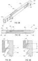
- Fig. 7A shows an initial state in which the pawl 152 is pressed against the toothless portion of the inner member 154, proximal to the teeth 164.
- Fig. 7B shows an intermediate state wherein the pawl has been slid over two teeth 164, which is indicative of an axial distance 2L along which the frame 120 foreshortened, beyond the minimal expansion diameter at which the valve may be locked, also termed minimal expansion diameter.
- FIG. 7C shows an optional final position of the pawl 152, locked against the teeth 164 pas the fifth tooth, which is indicative of an axial distance 5L along which the frame 120 foreshortened beyond the minimal expansion diameter, to the final expansion diameter, at which point the actuation assemblies 170 can be disengaged from the valve 114.
- the number of teeth is selected to cover the desired range of expansion diameters for the valve 114, ranging from a minimal expansion diameter defined by the first (e.g., proximal-most) tooth, to a maximal expansion diameter that may be defined by engagement of the pawl 152 with the teeth 164 past the last (e.g., distal-most) tooth.
- This range of expansion diameters corresponds to possible expansion diameters allowable by the ratcheting teeth 164, which may be equal to, or greater than, the range of target diameters of the valve 114, wherein the target diameters refer to a range of desired expansion diameters of the valve 114 within a patient's body, ranging from a minimal target diameter to a maximal target diameter.
- the target range of diameters is narrower than the range of expansion diameters allowable by the ratcheting mechanism, such that the minimal expansion diameter, at which the pawl 152 is engaged with, or proximal to, the first (e.g., proximal-most) tooth 164, is not greater than the minimal target diameter of the valve 114.
- the maximal expansion diameter, at which the pawl 152 is engaged with, or distal to, the last (e.g., distal-most) tooth 164 is at least as great as the maximal target diameter.
- a range of expansion diameters defined by the number of teeth 164 and the relative position between the pawl 152 and the teeth 164, may be in a range such as 23mm to 30mm, it may be that the target diameters are in the range of 26mm to 29mm.
- the plurality of ratcheting teeth 164 extend along a portion of the length of the inner member 154 adj acent the inner member proximal end portion 156. In other examples, the plurality of ratcheting teeth 164 can extend substantially the entire length of the inner member 154. In still other examples, the plurality of ratcheting teeth 164 can extend a portion of the length of the inner member adjacent the inner member distal end portion 158. The length of each tooth L dictates the resolution of discrete expansion diameters.
- the movement of the pawl 152 over the ratcheting teeth 164 generates click sounds as the pawl 152 slides over each tooth 164.
- Each click sound may be representative of the pawl 152 sliding over a single tooth 164 having a tooth length L, such that several consecutive click sounds generated during the movement of a pawl 152 over ratcheting teeth 164 of a corresponding inner member 154 may be indicative of a relative movement between the inner member 154 relative to the outer member 140 along a distance that can be substantially equal to L multiplied by the number of clicks.
- the at least one sound sensor 180 of the monitoring system includes at least one extracorporeal sound sensor 180 a .
- Fig. 8 showing a schematic example of a prosthetic valve expansion monitoring system 166 a comprising an extracorporeal sound sensor 180 a , that can be placed in contact with or in close proximity to the patient's body.
- the extracorporeal sound sensor 180 a is configured to be placed externally at or in the vicinity of the skin surface of a subject (i.e., a patient), and to externally measure sounds produced within the body of the subject.
- the extracorporeal sound sensor 180 a can be placed over the patient's chest, as shown in Fig. 8 , prior to or during a prosthetic valve implantation procedure.
- the monitoring system 166 further comprises an ambient noise sensor (not shown) configured to acquire environment noise and/or speech.
- the ambient noise sensor can be used to remove environmental noise from measured signals. Alternately, any other method of noise removal may additionally or alternatively be used.
- the prosthetic valve expansion monitoring system further comprises a control unit 194 configured to receive signals detected by the at least one sound sensor 180.
- control unit 194 comprises a processor.
- control unit 194 comprises a central processing unit (CPU), a microprocessor, a microcomputer, a programmable logic controller, an application-specific integrated circuit (ASIC) and/or a field-programmable gate array (FPGA), without limitation.
- CPU central processing unit
- ASIC application-specific integrated circuit
- FPGA field-programmable gate array
- the at least one sound sensor 180 can generate electric signals commensurate with click sounds generated by at least one expansion and locking assembly 138 of the prosthetic valve 114, and to transmit such signals, via wireless or wired communication appliances, for example to a control unit.
- Wireless communication can include a radio frequency (RF) link, an infrared link, a Bluetooth link, or any other known wireless communication methods.
- Wired communication can include a communication line 184, attached to the at least one sound sensor 180 at one end, and to a control unit (194) at the other end.
- an extracorporeal sound sensor 180 a can be attached to a communication line 184 a configured to transmit signals generated thereby to another extracorporeal component, such as an extracorporeal control unit 194 a , wherein the extracorporeal control unit can be coupled to, or in communication with, additional devices or components such as a display module 196 (e.g., extracorporeal display module 196 a shown in Fig. 8 ) and/or a communication component 198 (e.g., extracorporeal communication component 198 a shown in Fig. 8 ).
- a display module 196 e.g., extracorporeal display module 196 a shown in Fig. 8
- a communication component 198 e.g., extracorporeal communication component 198 a shown in Fig. 8
- extracorporeal sound sensor 180 a can be configured to detect heart sounds as well as click sounds, and to generate signals that can be distinguished, for example by the control unit 194 a . Signals of heart sounds and click sounds can be distinguished from each other due to having, for example, different amplitudes, waveforms and/or frequencies.
- Heart sound sensors are conventionally utilized for detection of sounds generated by heart activity, which include the opening and closing of the native heart valves and blood flow.
- the human heart sounds include a first major sound ("S1") and second major sound (“S2").
- the first major sound usually includes a mitral valve sound (“M1") and a tricuspid valve sound (“T1")
- the second major sound usually includes an aortic valve sound (“A2”) and a pulmonary valve sound (“P2").
- Heart sounds such as S1 and S2 are repetitive sounds generated by the ongoing cycling heart activity, while click sounds of expansion and locking assemblies are non-repetitive sounds that occur only during sliding of a pawl 152 over corresponding ratcheting teeth 164, and will have different amplitudes, waveforms and/or frequencies than those of heart sounds due to being generated by prosthetic, optionally metallic, components interacting with each other.
- a sound sensor 180 such as extracorporeal sound sensor 180 a
- Electric signals can be transmitted, for example via wireless communication, or via wired communication such as a communication line 184, to control unit 194, which can distinguish between the heart sounds and the click sounds, according to amplitudes, wavelengths and/or frequencies associated with signals of the different types of sounds, as well as according to identification of repetitive vs. non-repetitive sounds.
- extracorporeal sound sensor 180 a is a phonocardiogram sensor.
- heart sounds monitoring is not required during valve expansion, such that the heart sounds are actually part of background sounds that should be filtered in order to isolate only click sounds.
- the sound sensor 180 can be attached to other components of the delivery apparatus 102, besides the nosecone shaft, as will be further elaborated hereinbelow.
- the sound sensor 180 is attached to a component of the delivery apparatus 102 such that the distance between the sound sensor 180 and the pawl 152 (e.g., the closest pawl in case of a plurality of expansion and locking assemblies), during valve expansion, is not greater than 20 centimeters.
- the sound sensor 180 is attached to a component of the delivery apparatus 102 such that the distance between the sound sensor 180 and the pawl 152 (e.g., the closest pawl in case of a plurality of expansion and locking assemblies), during valve expansion, is not greater than 10 centimeters.
- the distance between the sound sensor 180 and the pawl 152 may change during valve expansion. In such cases, the distance should not exceed the above-mentioned values in a state of maximal valve expansion, i.e., when the prosthetic valve 114 is expanded to a maximal desired expansion diameter thereof.
- the prosthetic valve expansion monitoring system 166 can further comprise a control unit 194, that can receive signals generated by the at least one sound sensor 180, for example via a communication line 184 attached at one end (e.g., the distal end) to the at least one sound sensor 180, and at the opposite end (e.g., the proximal end) to the control unit 194.
- the communication line 184 can be configured to deliver measurement signals from the at least one sound sensor 180 to the control unit 194, and/or to deliver power to the at least one sound sensor 180.
- Measurement signals acquired by the at least one sound sensor 180 may provide real-time feedback regarding the valve expansion diameter during an implantation procedure.
- Such data may be displayed graphically, for example on an LCD screen 113a or LED lights 113b provided on the handle 110.
- the control unit 194 is operatively coupled to a display module 196, configured to relay visual representation of the measurement signals, or other signals or data derived from the measurement signals.
- display module 196 a is configured to relay data or information to be visually displayed via LCD screen 113a or LED lights 113b.
- the delivery apparatus 102 further comprises a sensor shaft 186 extending from the handle 110 through the delivery shaft 106.
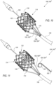
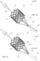
- Fig. 10 shows a distal region of the delivery assembly 100 of prosthetic valve expansion monitoring system 166°, wherein the sensor shaft 186 comprises a sensing head 188, which is illustrated extending distally from the delivery shaft 106.
- the actuation assemblies 170 are releasably coupled to the expansion and locking assemblies 138 during valve expansion procedures, such that vibration of a component of each expansion and locking assembly 138 can be advanced through a component of the respective actuation assembly 170 coupled thereto.
- both the inner member 154 and the actuator 170 coupled thereto are rigid components (e.g., metallic components)
- vibration of the inner member 154 can be axially advanced and cause the actuator 172 to vibrate therealong.
- communication line 184 f is attached to the outer surface of a corresponding actuation assembly 170, or wrapped there-around, for example in a helical pattern (not shown), from the vibration sensor 182 a to the handle 110, and optionally further extending into the handle 110.
- the communication line 184 f is attached to the outer surface of a sleeve 176.
- the delivery apparatus 102 includes a plurality of vibration sensors 182, attached to a plurality of actuation assemblies 170.
- the number of vibration sensors 182 can match the number of actuation assemblies 170, which in turn matches the number of expansion and locking assemblies 138.
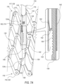
- Fig. 14 shows an example of a delivery apparatus 102 that includes three actuation assemblies 170a, 170b and 170c, coupled to three expansion and locking assemblies 138a, 138b and 138c, and three vibration sensors 182 a a, 182 a b and 182 a c attached to the actuation assemblies 170a, 170b and 170c, respectively.
- Three corresponding communication lines 184 f a, 184 f b and 184 f c can extend proximally from the vibration sensors 182 a a, 182 a b and 182 a c, respectively.
- FIG. 15 shows an example of a vibration sensor 182 a or a sound sensor 180 f attached to an external surface of a sleeve 176.
- sleeve 176 a is tightly disposed around actuator 172, such that vibrations of the actuator 172 are transmitted to the sleeve 176 a by contact.
- the inner surface of the sleeve 176 a may in contact with the outer surface of the actuator 172.
- the sleeve 176 should preferably allow the actuator 172 to be movable axially relative thereto, for example during the pulling of the inner member 154 thereby for valve expansion, with as little interference as possible therebetween.
- the sleeve 176 a can be tightly disposed around actuator 172 in a manner that a narrow gap is formed therebetween, sufficient to allow free telescoping movement of the actuator 172 with respect to the sleeve 176 a , yet narrow enough to allow vibrations of the actuator 172 to be transmitted to the sleeve 176 a .
- a lubricious coating may be provided on an outer surface of the actuator 172 and/or the inner surface of the sleeve 176.
- the lubricious coating can include Teflon, parylene, PTFE, polyethylene, polyvinylidene fluoride, and combinations thereof.
- Suitable materials for a lubricious coating also include other materials desirably having a coefficient of friction of 0.1 or less.
- Such coating can allow the sleeve 176 a to be tightly disposed around actuator 172 in a manner that will allow vibrations to be transmitted from the actuator 172 to the sleeve 176 a , so as to be easily sensed by a corresponding vibration sensor 182 a attached to the sleeve 176 a , while allowing the actuator 172 and the sleeve 176 a to be conveniently movable relative to each other along the axial axis.
- a vibration sensor 182 b , 182 c or a sound sensor 180 g , 180 h is disposed within the lumen defined by the sleeve 176, between the actuator 172 and the sleeve 176.
- Sleeve 176 b can have an inner diameter d2, larger than an outer diameter d1 of the actuator 172.
- the difference between d2 and d1 is at least twice as large as the thickness Ts of the vibration sensor 182 b , 182 c or the sound sensor 180 g , 180 h .
- sleeve 176 b has a uniform inner diameter d2, as shown in Fig. 16 .
- sleeve 176 c can have a varying inner diameter, such that the difference between the inner diameter of the sleeve 176 c and the outer diameter d1 of the actuator 172 is at least as great as twice the thickness Ts, at least at the region at which the vibration sensor 182 c or sound sensor 180 h is positioned, and potentially along most of the length of the actuation assembly 170, and include a tapering neck portion 177 distal to vibration sensor 182 c or sound sensor 180 h , as shown in Fig. 17 .
- communication line 184 g , 184 h is disposed within the lumen defined by the sleeve 176, between the actuator 172 and the sleeve 176, extending proximally from the vibration sensor 182 b , 182 c or the sound sensor 180 g , 180 h to the handle 110, and optionally further extending into the handle 110.
- Communication line 184 g , 184 h can be attached to the outer surface of the actuator 172, or wrapped there-around, for example in a helical pattern (not shown).
- communication line 184 g , 184 h can be attached to the inner surface of sleeve 176 b , 176 c .
- vibration sensors 182 can be attached to other portions of the actuation assemblies 170.
- vibration sensors 182 can be attached to proximal portions of the actuation assemblies 170, including configurations of vibration sensors 182 attached to proximal portions of the actuators 172 situated within the handle 110.
- actuators 172 are provided with rigidity that is sufficient to transmit vibrations from the inner members 154 coupled thereto all the way to their proximal portions (e.g., within the handle) in a manner that is sufficient to detect vibrations commensurate with the pawls 152 sliding over respective ratcheting teeth 164.
- Ambient sounds and noise may be present during the implantation and expansion procedure, including heart sounds, lung sounds, blood flow in the vicinity of the prosthetic valve 114 and/or the sound sensor 180, movement of various components such as the leaflets 133 of the leaflet assembly 132 that may move between open and closed states as the valve is expanded enough to allow blood flow therethrough, and the like.
- the control unit 194 is configured to filter ambient sounds and/or noise, so as to detect and isolate click sounds generated by the expansion and locking assemblies 138.
- control unit 194 comprises a processor for processing and interpreting measurement signals received from the at least one sound sensor 180 and/or the at least one vibration sensor 182.
- the control unit 194 may include software for interpreting and/or displaying data.
- a wide variety of algorithms can be used to provide warnings, for example to the clinician, associated with sensed signals interpretations.
- an operator of the delivery assembly 100 can quickly and easily obtain real-time assessment of the expanded diameter of the prosthetic valve 114.
- control unit 194 further comprises a memory member (not shown), such as an internal memory within the control unit 194, configured to store the signals received from any of the sound sensor 180 and/or the vibration sensor 182, and/or store interpreted data by the processor.
- a memory member may include a suitable memory chip or storage medium such as, for example, a PROM, EPROM, EEPROM, ROM, flash memory, solid state memory, or the like.
- a memory member can be integral with the control unit or may be removably coupled to the control unit.
- the measurement signals may be mathematically manipulated or processed by the control unit 194, in order to derive axial foreshortening and/or valve expansion diameter.
- the internal control unit 194 is configured to transmit, for example via the communication component 198, raw or interpreted data, including stored data, to an external control unit or any other external device, via either wired or wireless communication protocols.
- control unit 194 can be configured to receive electric signals detected by the at least one sound sensor 180, and to filter signals that may follow amplitudes, waveforms and/or frequencies that may be associated with ambient sounds and/or noise, leaving only the signals that may follow amplitudes, waveforms and/or frequencies that may be associated with click sounds.
- control unit 194 be configured to receive electric signals detected by the at least one sound sensor 180, and to filter signals that are present prior to initiation of valve expansion.
- control unit 194 may be associated with the actuation mechanism within the handle 110 that is configured to pull the actuators 172, such that an expansion initiation signal is generated at the onset of pulling the actuators 172, and is sent to the control unit 194, allowing the control unit to filter signals sensed by the at least one sound sensor 180 prior to the onset of pulling the actuators 172.
- control unit 194 is further configured to detect and count the number of click sounds.
- the axial foreshortening of the prosthetic valve 114 defined as the axial approximation of the inflow end 119 and the outflow end 117 toward each other during valve expansion, can be estimated by multiplying the number of detected clicks by the axial length of a ratcheting tooth L. For example, a count of a total of 5 clicks can be indicative of a valve foreshortening by a distance of about 5L.
- the radial expansion can then be derived from the estimated axial foreshortening. Assuming that the diameter of the prosthetic valve 114 at which the pawl 152 is engaged with the first ratcheting tooth 164 to generate the first click sound is known, this initial diameter can serve as the base value to which the additional expansion diameter is added.
- the at least one sound sensor 180 may be utilized to provide an indication, qualitative or quantitative evaluation, or any other feedback regarding the expanded diameter of prosthetic valve 114, in real-time, in-vivo, during a valve 114 implantation and expansion procedures.
- the estimated diameter may have an accuracy in the range of L.
- the prosthetic valve 114 may include a plurality of expansion and locking assemblies 138, such as three expansion and locking assemblies 138a, 138b and 138c in the illustrated examples.
- the distance by which the inner member 154 moves relative to the corresponding outer member 140 in each of the expansion and locking assemblies 138 may slightly differ from each other, and the click sounds generated by each may not necessarily be synchronized with each other.
- control unit is further configured to differentiate between click sounds of different expansion and locking assemblies based on identification of the time difference between such click sounds. For example, unsynchronized click sounds generated by different expansion and locking assemblies, detected at time intervals that are shorter than a predefined threshold, may be indicative of click sounds of two or more expansion and locking assemblies 138 actuated simultaneously, while time intervals that are longer than the predefined threshold may be indicative of the pawl of at least one expansion and locking assembly 138 sliding over a subsequent tooth 164.
- the length L of ratcheting teeth 164 may influence the accuracy of diameter estimation, based on counting click sounds detected by the at least one sound sensor 180.
- the relation between axial foreshortening of the valve and diameter expansion can be a non-linear relation, wherein the diameter of the valve can be increased by a value that is either shorter than, equal to, or larger than the axial foreshortening.
- the accuracy of estimating valve axial foreshortening may influence the accuracy of estimating the expansion diameter based on such relation. For example, a foreshortening of about 0.4 mm. in a maximal or near maximal expansion diameter of the valve may be translated to an increase in diameter of about 0.5 mm., such that an error range of about 2L of the estimated foreshortening may result in an error range of about 2.5L of the estimated expansion diameter.
- control unit 194 can be configured to receive electric signals detected by the at least one vibration sensor 182, and to filter signals that may follow amplitudes, waveforms and/or frequencies that may be associated with background vibrations, leaving only the signals that may follow amplitudes, waveforms and/or frequencies that may be associated with vibrations generated by the expansion and locking assemblies 138 during movement of the pawl 152 over each tooth 164.
- control unit 194 be configured to receive electric signals detected by the at least one vibration sensor 182, and to filter signals that are present prior to initiation of valve expansion.
- control unit 194 may be associated with the actuation mechanism within the handle 110 that is configured to pull the actuators 172, such that an expansion initiation signal is generated at the onset of pulling the actuators 172, and is sent to the control unit 194, allowing the control unit to filter signals sensed by the at least one vibration sensor 182 prior to the onset of pulling the actuators 172.
- control unit 194 is further configured to detect and count the number of vibrations generated by the expansion and locking assemblies 138 during movement of the pawl 152 over each tooth 164.
- the axial foreshortening, the derivation of the valve expanded diameter therefrom, and the accuracy of such estimations, may be similar to those described above with respect to the counted click sounds, mutatis mutandis.
- vibration sensor 182 may be advantageous over that of sound sensors 180, as a plurality of vibration sensors 182 can be coupled to a corresponding plurality of actuation assemblies 170, as shown for example in Fig. 14 , allowing the axial movement of each inner member 154 relative to a respective outer member 140 of each expansion and locking assembly 138 to be measured separately by a corresponding different vibration sensor 182.
- the signals from the plurality of vibration sensors 182 can then be transmitted to the control unit 194, which can in turn mathematically manipulate signals acquired within a predefined time period that may be associated with signals that may originate from different expansion and locking assemblies 138 but relate to the same range of frame foreshortening.
- Such mathematical manipulation can include for example averaging the axial translations of the plurality of expansion and locking assemblies 138, so as to improve the accuracy of the valve expanded diameter derived therefrom.
- signals from vibration sensors 182 attached to different actuation assemblies 170 serve to identify non-uniform expansion of the prosthetic valve 114, and to estimate the extent of such non-uniformity that can be displayed to the operator (e.g., clinician) of the delivery assembly 100.
- Information regarding non-uniformity of valve expansion may be of high significance and is not easily detectable by a sound sensor 180, as well as by other conventional (e.g., image based) assessments of the expansion diameter of the valve.
- Such data can be displayed (e.g., via display module 196 relaying display data to a display 112) either as textual data that includes numerical values of the various magnitudes of axial foreshortening and locations thereof across the prosthetic valve, as well as graphical representation of such regions and an estimated shape (e.g., non-circular shape) of the expanded prosthetic valve.
- textual data that includes numerical values of the various magnitudes of axial foreshortening and locations thereof across the prosthetic valve, as well as graphical representation of such regions and an estimated shape (e.g., non-circular shape) of the expanded prosthetic valve.
- this application discloses the additional examples enumerated below. It should be noted that one feature of an example in isolation or more than one feature of the example taken in combination and, optionally, in combination with one or more features of one or more further examples are further examples also falling within the disclosure of this application.
- a prosthetic valve expansion monitoring system comprising: a prosthetic valve comprising: a frame movable between a radially compressed configuration and a radially expanded configuration, and at least one expansion and locking assembly, comprising: an outer member, coupled to the frame at a first location, and comprising a spring biased arm with a pawl; and an inner member, coupled to the frame at a second location spaced apart from the first location, the inner member extending at least partially into the outer member, the inner member comprising a plurality of ratcheting teeth; a delivery apparatus comprising: a handle; a delivery shaft extending distally from the handle; and at least one actuation assembly, comprising: an actuator extending from the handle through the delivery shaft, and releasably coupled to the corresponding inner member; and a sleeve disposed around the corresponding actuator, at least one sound sensor configured to generate signals commensurate with click sounds generated during movement of the pawl over the ratcheting teeth; wherein the spring biased arm is biased
- Example 2 The system of any example herein, particularly example 1, wherein the at least one sound sensor is comprised within a sensor housing.
- Example 3 The system of any example herein, particularly example 1 or Error! Reference source not found., further comprising a control unit configured to: receive the signals from the at least one sound sensor; responsive to the received signals, determine the number of click sounds generated during the movement of the pawl; evaluate an expanded diameter of the prosthetic valve; and output an indication of the evaluated expanded diameter.
- Example 4 The system of any example herein, particularly example Error! Reference source not found., wherein the control unit is further configured to estimate the axial foreshortening of the frame by multiplying the number of click sounds by the length of a single ratcheting tooth, the evaluation of the expanded diameter being responsive to the estimated axial foreshortening.
- Example 5 The system of any example herein, particularly example Error! Reference source not found., wherein the evaluation of the expanded diameter is based on pre-stored relationships between axial foreshortening and radial expansion of the frame.
- Example 6 The method of any example herein, particularly any one of examples Error! Reference source not found. to Error! Reference source not found., wherein the at least one expansion and locking assembly comprises three expansion and locking assemblies, and wherein the control unit is further configured to differentiate between click sounds of different expansion and locking assemblies based on identification of the time difference between such click sounds.
- Example 8 The system of any example herein, particularly any one of examples 3 to 7, further comprising a communication component operatively coupled to the control unit.
- Example 12 The system of any example herein, particularly any one of examples 1 to 11, further comprising at least one communication line attached to the at least one sound sensor, and configured to transmit signals generated by the sound sensor.
- Example 13 The system of any example herein, particularly example 12, wherein the at least one communication line extends from the sound sensor toward and into the handle.
- Example 14 The system of any example herein, particularly example 12 or 13, wherein the communication line is further configured to deliver power to the sound sensor.
- Example 16 The system of any example herein, particularly example 15, wherein the microphone is selected from a piezoelectric, a piezoresistive, and a capacitive-type microphone.
- Example 17 The system of any example herein, particularly example 15, wherein the microphone is a MEMS microphone.
- Example 18 The system of any example herein, particularly any one of examples 1 to Error! Reference source not found., wherein the distance between the sound sensor and the pawl is not greater than 20 centimeters.
- Example 19 The system of any example herein, particularly example 18, wherein the distance between the sound sensor and the pawl is not greater than 10 centimeters.
- Example 20 The system of any example herein, particularly example 19, wherein the distance between the sound sensor and the pawl is not greater than 5 centimeters.
- Example 21 The system of any example herein, particularly any one of examples 1 to Error! Reference source not found., wherein the sound sensor is attached to the delivery apparatus.
- Example 22 The system of any example herein, particularly example 21, wherein the delivery apparatus further comprises a nosecone shaft extending distally from the handle through the delivery shaft, and a nosecone attached to a distal end of the nosecone shaft.
- Example 23 The system of any example herein, particularly example Error! Reference source not found., wherein the sound sensor is attached to the nosecone shaft.
- Example 24 The system of any example herein, particularly example Error! Reference source not found., wherein the sound sensor is attached to the nosecone.
- Example 25 The system of any example herein, particularly example 21, wherein the delivery apparatus further comprises a sensor shaft extending from the handle through the delivery shaft, wherein the sensor shaft comprises a sensing head comprising the sound sensor.
- Example 26 The system of any example herein, particularly example 21, wherein the sound sensor is attached to the delivery shaft.
- Example 36 The system of any example herein, particularly any one of examples 1 to 20, further comprising an independent catheter that is not attached to the delivery apparatus, wherein the independent catheter comprises a sensing head comprising the sound sensor.
- Example 38 The system of any example herein, particularly any one of examples 1 to Error! Reference source not found., wherein the sound sensor is an extracorporeal sound sensor, configured to externally measure sounds produced within the body of a subject.
- Example 39 The system of any example herein, particularly example 38, wherein the extracorporeal sound sensor is embedded within a precordial patch.
- a delivery assembly comprising: a prosthetic valve comprising: a frame movable between a radially compressed configuration and a radially expanded configuration, and at least one expansion and locking assembly, comprising: an outer member, coupled to the frame at a first location, and comprising a spring biased arm with a pawl; and an inner member, coupled to the frame at a second location spaced apart from the first location, the inner member extending at least partially into the outer member, the inner member comprising a plurality of ratcheting teeth; a delivery apparatus comprising: a handle; a delivery shaft extending distally from the handle; and at least one actuation assembly, comprising: an actuator extending from the handle through the delivery shaft, and releasably coupled to the corresponding inner member; and a sleeve disposed around the corresponding actuator, at least one vibration sensor attached to the at least one actuation assembly; wherein the spring biased arm is biased toward the inner member; wherein engagement of the pawl with the ratcheting
- Example 43 The delivery assembly of any example herein, particularly example 42, further comprising a control unit configured to: receive the signals from the at least one vibration sensor; responsive to the received signals, count the vibrations generated by the expansion and locking assembly during movement of the pawl over each ratcheting tooth; responsive to an outcome of the count of the vibrations, evaluate an expanded diameter of the prosthetic valve; and output an indication of the expanded diameter.
- a control unit configured to: receive the signals from the at least one vibration sensor; responsive to the received signals, count the vibrations generated by the expansion and locking assembly during movement of the pawl over each ratcheting tooth; responsive to an outcome of the count of the vibrations, evaluate an expanded diameter of the prosthetic valve; and output an indication of the expanded diameter.
- Example 44 The delivery assembly of any example herein, particularly example 43, wherein the control unit is further configured to estimate the axial foreshortening of the frame by multiplying the number of vibrations generated by the expansion and locking assembly during movement of the pawl over each ratcheting tooth, by the length of a single ratcheting tooth, the evaluation of the expanded diameter responsive to the estimated axial foreshortening.
- Example 45 The delivery assembly of any example herein, particularly example 44, wherein the evaluation of the expanded diameter of the prosthetic valve is based on pre-stored relationships between axial foreshortening and radial expansion of the frame.
- Example 46 The delivery assembly of any example herein, particularly any one of examples 43 to 45, wherein the at least expansion and locking assembly comprises three expansion and locking assemblies, wherein the at least one vibrations sensor comprises three vibration sensors, each vibration sensor attached to a separate actuation assembly coupled to a corresponding expansion and locking assembly, and wherein the control unit is further configured to identify signals acquired within a predefined time period and mathematically manipulate such signals.
- Example 47 The delivery assembly of any example herein, particularly example 46, wherein the mathematical manipulation comprises averaging the signals received within the predefined time period.
- Example 48 The delivery assembly of any example herein, particularly example 46 or 47, wherein the control unit is further configured to identify a non-uniform expansion of the prosthetic valve, the evaluation of the expanded diameter responsive to the identified non-uniform expansion.
- Example 49 The delivery assembly of any example herein, particularly example 48, wherein the identification of a non-uniform expansion comprises estimating the extent of axial foreshortening at more than two regions around the circumference of the prosthetic valve.
- Example 51 The delivery assembly of any example herein, particularly any one of examples 43 to 50, wherein the control unit is embedded within the handle.
- Example 53 The delivery assembly of any example herein, particularly example 13, wherein the communication component is embedded within the handle.
- Example 54 The delivery assembly of any example herein, particularly any one of examples 11 to 53, further comprising a display module operatively coupled to the control unit.
- Example 57 The delivery assembly of any example herein, particularly example Error! Reference source not found., wherein the handle further comprises an LCD screen and/or LED lights, and wherein the display module is configured to relay visual representation of the signals, or data derived from the signals, to the LCD screen and/or the LED lights.
- Example 58 The delivery assembly of any example herein, particularly any one of examples 42 to 57, further comprising at least one communication line attached to the at least one vibration sensor, and configured to transmit signals detected by the vibration sensor.
- Example 59 The delivery assembly of any example herein, particularly example Error! Reference source not found., wherein the at least one communication line extends from the vibration sensor toward and into the handle.
- Example 60 The delivery assembly of any example herein, particularly example 58 or 59, wherein the communication line is further configured to deliver power to the vibration sensor.
- Example 61 The delivery assembly of any example herein, particularly any one of examples 10 to 60, wherein the vibration sensor comprises an accelerometer.
- Example 62 The delivery assembly of any example herein, particularly example 14, wherein the at least one vibration sensor comprises a single vibration sensor attached to one of the actuation assemblies.
- Example 63 The delivery assembly of any example herein, particularly example 61, wherein the at least one vibration sensor comprises three vibration sensors, each attached to a separate actuation assembly.
- Example 64 The delivery assembly of any example herein, particularly any one of examples 10 to 63, wherein the vibration sensor is attached to the sleeve.
- Example 65 The delivery assembly of any example herein, particularly example Error! Reference source not found., wherein the sleeve is tightly disposed around the corresponding actuator.
- Example 66 The delivery assembly of any example herein, particularly example 64 or 65, wherein the actuation assembly further comprises a lubricious coating provided on an outer surface of the actuator and/or the inner surface of the sleeve.
- Example 68 The delivery assembly of any example herein, particularly example Error! Reference source not found. or 67, wherein the lubricious coating has a coefficient of friction of 0.1 or less.
- Example 69 The delivery assembly of any example herein, particularly any one of examples 10 to 68, wherein the vibration sensor is disposed between the actuator and the sleeve.
- Example 70 The delivery assembly of any example herein, particularly example 19, wherein the vibration sensor is attached to the actuator.
- Example 71 The delivery assembly of any example herein, particularly example 19 or 70, wherein the difference between an inner diameter of the sleeve and an outer diameter of the actuator is at least twice as large as the thickness of the vibration sensor.
- Example 72 The delivery assembly of any example herein, particularly example 69 or 70, wherein the sleeve has a non-uniform inner diameter such that the difference between the inner diameter of the sleeve and an outer diameter of the actuator is at least twice as large as the thickness of the vibration sensor at the region at which the vibration sensor is positioned, and wherein the sleeve comprises a neck portion tapering distally inward to a narrower inner diameter of the sleeve.
- Example 76 The method of any example herein, particularly example 74, wherein the sound sensor is attached to the nosecone.
- Example 80 The method of any example herein, particularly example 74, wherein the evaluation of the expanded diameter is performed by a control unit embedded within the handle.
- Example 82 The method of any example herein, particularly example 81, wherein the handle comprises an actuation mechanism configured to pull the actuators, wherein the method further comprises generating an initiation signal at the onset of pulling the actuators by the actuation mechanism, and wherein the filtering of signals associated with ambient sounds and/or noise comprises filtering signals sensed by the at least one sound sensor prior to the initiation signal.
- Example 84 The method of any example herein, particularly example Error! Reference source not found., further comprising a step of estimating the axial foreshortening of the frame by multiplying the number of click sounds by the length of a single ratcheting tooth, the evaluation being responsive to the estimated axial foreshortening.
- Example 86 The method of any example herein, particularly any one of examples Error! Reference source not found. to 85, wherein the prosthetic valve comprises three expansion and locking assemblies, and wherein the method further comprises differentiating between click sounds of different expansion and locking assemblies based on identification of the time difference between such click sounds, the evaluation of the expanded diameter being responsive to the difference between the click sounds.
- Example 87 A method of estimating the expanded diameter of a prosthetic valve, comprising: providing a prosthetic valve comprising a frame movable between a radially compressed configuration and a radially expanded configuration, and at least one expansion and locking assembly comprising an outer member coupled to the frame at a first location and comprising a spring biased arm with a pawl, and an inner member, coupled to the frame at a second location spaced apart from the first location and comprising a plurality of ratcheting teeth, wherein the spring biased arm is biased toward the inner member; pulling the inner member relative to the outer member, wherein engagement of the pawl with the ratcheting teeth facilitates axial foreshortening and radial expansion of the frame; generating, by at least one vibration sensor, signals commensurate with vibrations generated by the expansion and locking assembly during movement of the pawl over each ratcheting tooth; and evaluating, based on the number of detected vibrations generated during movement of the pawl over each ratcheting tooth, the expanded diameter of
- Example 88 The method of any example herein, particularly example Error! Reference source not found., wherein the vibration sensor is attached to at least one actuation assembly comprising an actuator extending from a handle and releasably coupled to the corresponding inner member, and a sleeve disposed around the corresponding actuator.
- Example 89 The method of any example herein, particularly example 88, wherein the vibration sensor is attached to the sleeve.
- Example 92 The method of any one of examples to 91, further comprising the step of filtering signals that may follow amplitudes, waveforms and/or frequencies that may be associated with ambient background vibrations, leaving only the signals that may follow amplitudes, waveforms and/or frequencies that may be associated with vibrations generated by the expansion and locking assembly during movement of the pawl over each ratcheting tooth.
Landscapes
- Health & Medical Sciences (AREA)
- Cardiology (AREA)
- Engineering & Computer Science (AREA)
- Biomedical Technology (AREA)
- Heart & Thoracic Surgery (AREA)
- Transplantation (AREA)
- Oral & Maxillofacial Surgery (AREA)
- Vascular Medicine (AREA)
- Life Sciences & Earth Sciences (AREA)
- Animal Behavior & Ethology (AREA)
- General Health & Medical Sciences (AREA)
- Public Health (AREA)
- Veterinary Medicine (AREA)
- Mechanical Engineering (AREA)
- Prostheses (AREA)
Applications Claiming Priority (3)
| Application Number | Priority Date | Filing Date | Title |
|---|---|---|---|
| US202063094099P | 2020-10-20 | 2020-10-20 | |
| PCT/US2021/055563 WO2022086931A1 (en) | 2020-10-20 | 2021-10-19 | Sound and vibration sensors for estimating prosthetic valve diameter during expansion |
| EP21816569.4A EP4231966B1 (de) | 2020-10-20 | 2021-10-19 | Schall- und vibrationssensoren zur schätzung des durchmessers einer klappenprothese während der expansion |
Related Parent Applications (1)
| Application Number | Title | Priority Date | Filing Date |
|---|---|---|---|
| EP21816569.4A Division EP4231966B1 (de) | 2020-10-20 | 2021-10-19 | Schall- und vibrationssensoren zur schätzung des durchmessers einer klappenprothese während der expansion |
Publications (2)
| Publication Number | Publication Date |
|---|---|
| EP4537791A2 true EP4537791A2 (de) | 2025-04-16 |
| EP4537791A3 EP4537791A3 (de) | 2025-06-18 |
Family
ID=78820155
Family Applications (2)
| Application Number | Title | Priority Date | Filing Date |
|---|---|---|---|
| EP24206617.3A Pending EP4537791A3 (de) | 2020-10-20 | 2021-10-19 | Schall- und vibrationssensoren zur schätzung des durchmessers einer klappenprothese während der expansion |
| EP21816569.4A Active EP4231966B1 (de) | 2020-10-20 | 2021-10-19 | Schall- und vibrationssensoren zur schätzung des durchmessers einer klappenprothese während der expansion |
Family Applications After (1)
| Application Number | Title | Priority Date | Filing Date |
|---|---|---|---|
| EP21816569.4A Active EP4231966B1 (de) | 2020-10-20 | 2021-10-19 | Schall- und vibrationssensoren zur schätzung des durchmessers einer klappenprothese während der expansion |
Country Status (3)
| Country | Link |
|---|---|
| US (1) | US20230255752A1 (de) |
| EP (2) | EP4537791A3 (de) |
| WO (1) | WO2022086931A1 (de) |
Families Citing this family (3)
| Publication number | Priority date | Publication date | Assignee | Title |
|---|---|---|---|---|
| EP4221636A1 (de) * | 2020-09-30 | 2023-08-09 | Edwards Lifesciences Corporation | Abgabevorrichtung für ein mechanisch expandierbares ventil |
| WO2023137024A1 (en) * | 2022-01-17 | 2023-07-20 | Edwards Lifesciences Corporation | Mechanical wave sensor for detecting detachment of prosthetic valve actuator |
| CN117534901B (zh) * | 2024-01-09 | 2024-04-09 | 瑞声光电科技(常州)有限公司 | 一种橡胶音膜及发声器件及其应用 |
Citations (7)
| Publication number | Priority date | Publication date | Assignee | Title |
|---|---|---|---|---|
| US6730118B2 (en) | 2001-10-11 | 2004-05-04 | Percutaneous Valve Technologies, Inc. | Implantable prosthetic valve |
| US6767362B2 (en) | 2000-04-06 | 2004-07-27 | Edwards Lifesciences Corporation | Minimally-invasive heart valves and methods of use |
| US6908481B2 (en) | 1996-12-31 | 2005-06-21 | Edwards Lifesciences Pvt, Inc. | Value prosthesis for implantation in body channels |
| US7993394B2 (en) | 2008-06-06 | 2011-08-09 | Ilia Hariton | Low profile transcatheter heart valve |
| US8252202B2 (en) | 2007-05-17 | 2012-08-28 | Dic Corporation | Nematic liquid crystal composition and bistable nematic liquid crystal display |
| US20180153689A1 (en) | 2016-12-06 | 2018-06-07 | Edwards Lifesciences Corporation | Mechanically expanding heart valve and delivery apparatus therefor |
| US20180325665A1 (en) | 2017-05-15 | 2018-11-15 | Edwards Lifesciences Corporation | Devices and methods of commissure formation for prosthetic heart valve |
Family Cites Families (21)
| Publication number | Priority date | Publication date | Assignee | Title |
|---|---|---|---|---|
| US5480423A (en) * | 1993-05-20 | 1996-01-02 | Boston Scientific Corporation | Prosthesis delivery |
| US7758625B2 (en) * | 2003-09-12 | 2010-07-20 | Abbott Vascular Solutions Inc. | Delivery system for medical devices |
| US7553324B2 (en) * | 2003-10-14 | 2009-06-30 | Xtent, Inc. | Fixed stent delivery devices and methods |
| US7887574B2 (en) * | 2003-12-23 | 2011-02-15 | Scimed Life Systems, Inc. | Stent delivery catheter |
| US7326236B2 (en) * | 2003-12-23 | 2008-02-05 | Xtent, Inc. | Devices and methods for controlling and indicating the length of an interventional element |
| US7959666B2 (en) * | 2003-12-23 | 2011-06-14 | Sadra Medical, Inc. | Methods and apparatus for endovascularly replacing a heart valve |
| WO2006097931A2 (en) * | 2005-03-17 | 2006-09-21 | Valtech Cardio, Ltd. | Mitral valve treatment techniques |
| JP5149150B2 (ja) * | 2005-03-25 | 2013-02-20 | ミトラル・ソリューションズ・インコーポレイテッド | 解剖学的なオリフィス又は内腔の内周を制御するための方法及び装置 |
| US7938851B2 (en) * | 2005-06-08 | 2011-05-10 | Xtent, Inc. | Devices and methods for operating and controlling interventional apparatus |
| US9814611B2 (en) * | 2007-07-31 | 2017-11-14 | Edwards Lifesciences Cardiaq Llc | Actively controllable stent, stent graft, heart valve and method of controlling same |
| US8652202B2 (en) * | 2008-08-22 | 2014-02-18 | Edwards Lifesciences Corporation | Prosthetic heart valve and delivery apparatus |
| ES2931210T3 (es) * | 2012-11-21 | 2022-12-27 | Edwards Lifesciences Corp | Mecanismos de retención para válvulas cardiacas protésicas |
| WO2015058808A1 (en) * | 2013-10-25 | 2015-04-30 | Kephalios S.A.S. | Adjustable annuloplasty ring and system |
| CN108338853B (zh) * | 2017-01-24 | 2024-07-12 | 上海氪励铵勤科技发展有限公司 | 一种组织压缩装置 |
| AU2021221975A1 (en) * | 2020-02-17 | 2022-09-22 | Canary Medical Switzerland Ag | Vascular sensing system |
| US11627484B2 (en) * | 2021-06-30 | 2023-04-11 | Qualcomm Incorporated | ULCI triggered CLI measurement |
| WO2023137024A1 (en) * | 2022-01-17 | 2023-07-20 | Edwards Lifesciences Corporation | Mechanical wave sensor for detecting detachment of prosthetic valve actuator |
| CN119677485A (zh) * | 2022-07-08 | 2025-03-21 | 爱德华兹生命科学公司 | 用于治疗钙化的心脏瓣膜的系统和方法 |
| CN120417858A (zh) * | 2022-12-20 | 2025-08-01 | 杭州启明医疗器械股份有限公司 | 经导管输送系统及人工心脏瓣膜的释放方法 |
| US20250205048A1 (en) * | 2023-12-26 | 2025-06-26 | St. Jude Medical, Cardiology Division, Inc. | Smart Balloon Inflation System for Transcatheter Heart Implantation |
| WO2025188826A1 (en) * | 2024-03-06 | 2025-09-12 | Edwards Lifesciences Corporation | Tissue perforation systems and handles thereof |
-
2021
- 2021-10-19 EP EP24206617.3A patent/EP4537791A3/de active Pending
- 2021-10-19 WO PCT/US2021/055563 patent/WO2022086931A1/en not_active Ceased
- 2021-10-19 EP EP21816569.4A patent/EP4231966B1/de active Active
-
2023
- 2023-04-20 US US18/136,944 patent/US20230255752A1/en active Pending
Patent Citations (9)
| Publication number | Priority date | Publication date | Assignee | Title |
|---|---|---|---|---|
| US6908481B2 (en) | 1996-12-31 | 2005-06-21 | Edwards Lifesciences Pvt, Inc. | Value prosthesis for implantation in body channels |
| US6767362B2 (en) | 2000-04-06 | 2004-07-27 | Edwards Lifesciences Corporation | Minimally-invasive heart valves and methods of use |
| US6730118B2 (en) | 2001-10-11 | 2004-05-04 | Percutaneous Valve Technologies, Inc. | Implantable prosthetic valve |
| US7393360B2 (en) | 2001-10-11 | 2008-07-01 | Edwards Lifesciences Pvt, Inc. | Implantable prosthetic valve |
| US7510575B2 (en) | 2001-10-11 | 2009-03-31 | Edwards Lifesciences Corporation | Implantable prosthetic valve |
| US8252202B2 (en) | 2007-05-17 | 2012-08-28 | Dic Corporation | Nematic liquid crystal composition and bistable nematic liquid crystal display |
| US7993394B2 (en) | 2008-06-06 | 2011-08-09 | Ilia Hariton | Low profile transcatheter heart valve |
| US20180153689A1 (en) | 2016-12-06 | 2018-06-07 | Edwards Lifesciences Corporation | Mechanically expanding heart valve and delivery apparatus therefor |
| US20180325665A1 (en) | 2017-05-15 | 2018-11-15 | Edwards Lifesciences Corporation | Devices and methods of commissure formation for prosthetic heart valve |
Also Published As
| Publication number | Publication date |
|---|---|
| EP4231966B1 (de) | 2024-10-16 |
| EP4537791A3 (de) | 2025-06-18 |
| EP4231966A1 (de) | 2023-08-30 |
| WO2022086931A1 (en) | 2022-04-28 |
| US20230255752A1 (en) | 2023-08-17 |
Similar Documents
| Publication | Publication Date | Title |
|---|---|---|
| US20230255752A1 (en) | Sound and vibration sensors for estimating prosthetic valve diameter during expansion | |
| US20220287851A1 (en) | Methods of personalizing drug treatment based on real-time pressure gradient measurements | |
| US11382753B2 (en) | Devices and methods for positioning and monitoring tether load for prosthetic mitral valve | |
| JP6991988B2 (ja) | 一体化されたセンサおよび送信機を備える弁インプラント | |
| US12539212B2 (en) | Flex sensors for measuring real-time valve diameter during procedure | |
| US9808201B2 (en) | Sensors for prosthetic heart devices | |
| EP3182932B1 (de) | Sensoren für künstliche herzvorrichtungen | |
| US20220039670A1 (en) | Heart failure monitor | |
| US20220331132A1 (en) | Devices and methods for prosthetic valve diameter estimation | |
| US20220257128A1 (en) | Real time measurements of physiological parameters associated with heart valve replacement | |
| US20240358506A1 (en) | Mechanical wave sensor for detecting detachment of prosthetic valve actuator | |
| EP3541460B1 (de) | Einführvorrichtungen und wandappositionsabtastung |
Legal Events
| Date | Code | Title | Description |
|---|---|---|---|
| PUAI | Public reference made under article 153(3) epc to a published international application that has entered the european phase |
Free format text: ORIGINAL CODE: 0009012 |
|
| STAA | Information on the status of an ep patent application or granted ep patent |
Free format text: STATUS: THE APPLICATION HAS BEEN PUBLISHED |
|
| AC | Divisional application: reference to earlier application |
Ref document number: 4231966 Country of ref document: EP Kind code of ref document: P |
|
| AK | Designated contracting states |
Kind code of ref document: A2 Designated state(s): AL AT BE BG CH CY CZ DE DK EE ES FI FR GB GR HR HU IE IS IT LI LT LU LV MC MK MT NL NO PL PT RO RS SE SI SK SM TR |
|
| PUAL | Search report despatched |
Free format text: ORIGINAL CODE: 0009013 |
|
| P01 | Opt-out of the competence of the unified patent court (upc) registered |
Free format text: CASE NUMBER: APP_18502/2025 Effective date: 20250416 |
|
| AK | Designated contracting states |
Kind code of ref document: A3 Designated state(s): AL AT BE BG CH CY CZ DE DK EE ES FI FR GB GR HR HU IE IS IT LI LT LU LV MC MK MT NL NO PL PT RO RS SE SI SK SM TR |
|
| RIC1 | Information provided on ipc code assigned before grant |
Ipc: A61F 2/24 20060101AFI20250509BHEP |
|
| STAA | Information on the status of an ep patent application or granted ep patent |
Free format text: STATUS: REQUEST FOR EXAMINATION WAS MADE |
|
| 17P | Request for examination filed |
Effective date: 20251218 |
|
| GRAP | Despatch of communication of intention to grant a patent |
Free format text: ORIGINAL CODE: EPIDOSNIGR1 |
|
| STAA | Information on the status of an ep patent application or granted ep patent |
Free format text: STATUS: GRANT OF PATENT IS INTENDED |