EP4537866A1 - Système d'irrigation à commande de gonflage améliorée - Google Patents
Système d'irrigation à commande de gonflage améliorée Download PDFInfo
- Publication number
- EP4537866A1 EP4537866A1 EP23202446.3A EP23202446A EP4537866A1 EP 4537866 A1 EP4537866 A1 EP 4537866A1 EP 23202446 A EP23202446 A EP 23202446A EP 4537866 A1 EP4537866 A1 EP 4537866A1
- Authority
- EP
- European Patent Office
- Prior art keywords
- inflation
- retention member
- electrically operated
- catheter
- inflatable retention
- Prior art date
- Legal status (The legal status is an assumption and is not a legal conclusion. Google has not performed a legal analysis and makes no representation as to the accuracy of the status listed.)
- Pending
Links
Images



Classifications
-
- A—HUMAN NECESSITIES
- A61—MEDICAL OR VETERINARY SCIENCE; HYGIENE
- A61M—DEVICES FOR INTRODUCING MEDIA INTO, OR ONTO, THE BODY; DEVICES FOR TRANSDUCING BODY MEDIA OR FOR TAKING MEDIA FROM THE BODY; DEVICES FOR PRODUCING OR ENDING SLEEP OR STUPOR
- A61M3/00—Medical syringes, e.g. enemata; Irrigators
- A61M3/02—Enemata; Irrigators
- A61M3/0279—Cannula; Nozzles; Tips; their connection means
- A61M3/0295—Cannula; Nozzles; Tips; their connection means with inflatable balloon
-
- A—HUMAN NECESSITIES
- A61—MEDICAL OR VETERINARY SCIENCE; HYGIENE
- A61M—DEVICES FOR INTRODUCING MEDIA INTO, OR ONTO, THE BODY; DEVICES FOR TRANSDUCING BODY MEDIA OR FOR TAKING MEDIA FROM THE BODY; DEVICES FOR PRODUCING OR ENDING SLEEP OR STUPOR
- A61M25/00—Catheters; Hollow probes
- A61M25/10—Balloon catheters
- A61M25/1018—Balloon inflating or inflation-control devices
- A61M25/10184—Means for controlling or monitoring inflation or deflation
-
- A—HUMAN NECESSITIES
- A61—MEDICAL OR VETERINARY SCIENCE; HYGIENE
- A61M—DEVICES FOR INTRODUCING MEDIA INTO, OR ONTO, THE BODY; DEVICES FOR TRANSDUCING BODY MEDIA OR FOR TAKING MEDIA FROM THE BODY; DEVICES FOR PRODUCING OR ENDING SLEEP OR STUPOR
- A61M3/00—Medical syringes, e.g. enemata; Irrigators
- A61M3/02—Enemata; Irrigators
- A61M3/0202—Enemata; Irrigators with electronic control means or interfaces
-
- A—HUMAN NECESSITIES
- A61—MEDICAL OR VETERINARY SCIENCE; HYGIENE
- A61M—DEVICES FOR INTRODUCING MEDIA INTO, OR ONTO, THE BODY; DEVICES FOR TRANSDUCING BODY MEDIA OR FOR TAKING MEDIA FROM THE BODY; DEVICES FOR PRODUCING OR ENDING SLEEP OR STUPOR
- A61M3/00—Medical syringes, e.g. enemata; Irrigators
- A61M3/02—Enemata; Irrigators
- A61M3/0233—Enemata; Irrigators characterised by liquid supply means, e.g. from pressurised reservoirs
- A61M3/0254—Enemata; Irrigators characterised by liquid supply means, e.g. from pressurised reservoirs the liquid being pumped
- A61M3/0258—Enemata; Irrigators characterised by liquid supply means, e.g. from pressurised reservoirs the liquid being pumped by means of electric pumps
-
- A—HUMAN NECESSITIES
- A61—MEDICAL OR VETERINARY SCIENCE; HYGIENE
- A61M—DEVICES FOR INTRODUCING MEDIA INTO, OR ONTO, THE BODY; DEVICES FOR TRANSDUCING BODY MEDIA OR FOR TAKING MEDIA FROM THE BODY; DEVICES FOR PRODUCING OR ENDING SLEEP OR STUPOR
- A61M2205/00—General characteristics of the apparatus
- A61M2205/33—Controlling, regulating or measuring
- A61M2205/3331—Pressure; Flow
- A61M2205/3334—Measuring or controlling the flow rate
-
- A—HUMAN NECESSITIES
- A61—MEDICAL OR VETERINARY SCIENCE; HYGIENE
- A61M—DEVICES FOR INTRODUCING MEDIA INTO, OR ONTO, THE BODY; DEVICES FOR TRANSDUCING BODY MEDIA OR FOR TAKING MEDIA FROM THE BODY; DEVICES FOR PRODUCING OR ENDING SLEEP OR STUPOR
- A61M2205/00—General characteristics of the apparatus
- A61M2205/35—Communication
- A61M2205/3576—Communication with non implanted data transmission devices, e.g. using external transmitter or receiver
- A61M2205/3584—Communication with non implanted data transmission devices, e.g. using external transmitter or receiver using modem, internet or Bluetooth®
-
- A—HUMAN NECESSITIES
- A61—MEDICAL OR VETERINARY SCIENCE; HYGIENE
- A61M—DEVICES FOR INTRODUCING MEDIA INTO, OR ONTO, THE BODY; DEVICES FOR TRANSDUCING BODY MEDIA OR FOR TAKING MEDIA FROM THE BODY; DEVICES FOR PRODUCING OR ENDING SLEEP OR STUPOR
- A61M2205/00—General characteristics of the apparatus
- A61M2205/50—General characteristics of the apparatus with microprocessors or computers
- A61M2205/502—User interfaces, e.g. screens or keyboards
-
- A—HUMAN NECESSITIES
- A61—MEDICAL OR VETERINARY SCIENCE; HYGIENE
- A61M—DEVICES FOR INTRODUCING MEDIA INTO, OR ONTO, THE BODY; DEVICES FOR TRANSDUCING BODY MEDIA OR FOR TAKING MEDIA FROM THE BODY; DEVICES FOR PRODUCING OR ENDING SLEEP OR STUPOR
- A61M2205/00—General characteristics of the apparatus
- A61M2205/50—General characteristics of the apparatus with microprocessors or computers
- A61M2205/52—General characteristics of the apparatus with microprocessors or computers with memories providing a history of measured variating parameters of apparatus or patient
-
- A—HUMAN NECESSITIES
- A61—MEDICAL OR VETERINARY SCIENCE; HYGIENE
- A61M—DEVICES FOR INTRODUCING MEDIA INTO, OR ONTO, THE BODY; DEVICES FOR TRANSDUCING BODY MEDIA OR FOR TAKING MEDIA FROM THE BODY; DEVICES FOR PRODUCING OR ENDING SLEEP OR STUPOR
- A61M25/00—Catheters; Hollow probes
- A61M25/10—Balloon catheters
- A61M25/1018—Balloon inflating or inflation-control devices
- A61M25/10184—Means for controlling or monitoring inflation or deflation
- A61M25/10187—Indicators for the level of inflation or deflation
- A61M25/10188—Inflation or deflation data displays
Definitions
- the present invention relates to an irrigation system comprising a catheter with an inflatable retention member.
- the irrigation system is particularly intended for rectal, transanal and/or stomal irrigation, and is suitable for self-administration of an irrigation liquid.
- a second lumen may be provided to deliver e.g. irrigation fluid to the body cavity, for drainage of a liquid or the like, such as feces in case of a rectal catheter or urine in case of an indwelling urinary catheter, from the body cavity, etc.
- the inflatable retention member preferably surrounds the insertion end of the catheter and preferably has a toroidal shape when fully inflated.
- US 2016/0193403 by the same applicant discloses an irrigation system in which balloon inflation is controlled in accordance with pre-set inflation levels.
- the inflated size of the balloon may sometime vary from user to user, and also sometimes from time to time for the same user.
- the inflated size of the balloon may also vary depending on differences in the material of the balloon, due to product variations, tolerances, etc.
- EP 2 683 424 discloses an electrically operated transanal irrigation system, where inflation of an inflatable balloon may be controlled by a pressure sensor.
- US 2014/0052063 discloses an irrigation system comprising a catheter with an inflatable balloon. A control system is provided for prevention of over-inflation of the balloon.
- WO 2016/095929 discloses an electrically operated rectal irrigation system. It discloses the use of an electric pump for inflation of a balloon, and the pumping is controlled based on time duration or number of pump revolutions.
- EP 3 338 827 discloses a system and method for controlling inflation of an inflatable balloon where an electrically operated pump is controlled based on both a measured pressure in the balloon and a determined total duration of the pumping.
- an irrigation system for medical use comprising:
- an irrigation system for medical use comprising:
- continuously determining is meant a determination which is continuous over a certain period of time, such as during the entire inflation step, during the entire time the pump is active, during the entire irrigation process, at all times, or the like.
- Catheters with inflatable retention members are used in many medical procedures where there is a need to retain the catheter in an inserted position during use.
- catheters are commonly used when the catheter is intended for insertion into the rectum, so-called rectal catheters, for example for use in anal irrigation systems, and for indwelling urinary catheters, for draining of urine from the bladder.
- An appropriate inflation level should be such that the catheter remains in place during use, but should also be such that it does not cause unnecessary discomfort and harm to the user, and in particular the inflatable retention member should not be overinflated to such an extent that there is a risk of burst or explosion of the inflatable retention member.
- the inflatable retention member may also function to prevent the irrigation liquid from leaking out during transanal irrigation.
- the appropriate inflation level of the inflatable retention member is difficult to determine beforehand, since it depends on the type of use and the size and type of catheter. It is also dependent on the preferences of the user; some users want the inflatable retention member to be quite large when inflated, whereas other users are more sensitive, and feel discomfort already at relatively small size. Further, this may also vary over time for one and the same user, depending e.g. on the condition of the colon, the general condition of the user, etc.
- the present invention allows the user or operator to control the inflation of the inflatable retention member precisely and safely. Since the present fluid volume is determined based on both an estimated inflation fluid volume and an estimated deflation fluid volume, the control is based on a current fluid volume, regardless of whether periods of deflation has occurred during inflation or not. Thus, the volume safety threshold is used in relation to the present fluid volume, which is continuously estimated upwards and downwards, depending on whether the inflatable retention member is inflated or deflated, respectively. This allows for the user to repeatedly inflate and deflate the inflatable retention member, in order to find a comfortable and adequate inflation level.
- control of the inflatable retention element based on an estimated present fluid volume is much more reliable and accurate than e.g. conventional control, based on pressure measurements.
- muscle contraction in the rectum may result in high pressure in the retention member even at fairly small volumes.
- in the trachea there are periods of high pressure during the respiratory cycle.
- the pressure variation is very low, making it very difficult to adequately control the inflation size solely based on the pressure level.
- differences in the inflatable retention members such as differences in material, differences in how the catheter has been previously used, etc.
- the control may also be realized in a very cost-effective manner, and without the need for costly and complicated sensors and the like.
- the present invention is based on the understanding that the volume of an inflatable retention member can be determined with great accuracy based on knowledge of the pressure in the inflatable retention elements, and the fluid flow into and out from the inflatable retention member, which may be estimated based on how and how long the electrically operated pump and the electrically operated valve are activated.
- the controller can determine an inflation flow rate into the inflatable retention member from the electrically operated pump, and a deflation flow rate out from the inflatable retention member through the electrically operated valve. Aggregated and integrated over time, the inflation flow rate can be used to continuously determine an inflation fluid volume, and in the same way the deflation flow rate can be used to continuously determine a deflation fluid volume. A present fluid volume in the inflatable retention member could then continuously be determined as the inflation fluid volume reduced by the deflation fluid volume.
- t s Time ⁇ T t K Temperature difference between inside the retention member and outside the system in the instant t. R constant Ideal, or universal, gas constant. P mbar Pressure inside the retention member. k - Count of the number of inflation periods. t k_inf_on s Time when an inflation period started. t k_inf_off s Time when an inflation period stopped. ⁇ inf moles/s Mole flow of fluid moles entering the retention member. m - Count of the number of deflation periods. t m_der_on s Time when a deflation period started. t m_def_off s Time when a deflation period stopped.
- ⁇ def moles/s Mole flow of fluid moles leaving the retention member It's represented by a function of time, difference in temperature and difference in pressure. ⁇ P t mbar Pressure difference between inside the retention member and outside the system in the instant t.
- the electrically operated pump may, whenever activated, always be operated at a known speed, such as at a constant speed or a speed determined by a sensor or the like. This makes it possible to determine, e.g. by simple experimental measurements, the air flow provided by the electrically operated pump at different balloon pressure levels.
- the pump need not be operated at a constant speed or with a steady state power.
- the voltage and the current may also be varied during operation of the pump.
- the system may further comprise a power sensor for determining at least one of a current and a voltage supplied to the electrically operated pump.
- the controller may then be arranged to determine the inflation flow rate based on the current and/or voltage supplied to the electrically operated pump, based on input from the power sensor.
- the relationship between the airflow and the power, at various counter pressure levels, can again easily be determined experimentally.
- the system may comprise a speed sensor, such as a tachometer or encoder, to determine the rotation speed of the pump.
- the electrically operated valve may, whenever activated, and possibly after a short ramping up due to inertia, always be fully opened.
- the electrically operated valve may be operated intermittently between a fully closed state and a fully opened state. This makes it possible to determine, e.g. by simple experimental measurements, the air flow provided through the electrically operated valve when in an open state at different balloon pressure levels.
- the electrically operated valve is arranged to always be in one of two states, viz. a fully opened state and a fully closed state.
- the valve could be operated intermittently, to switch between the binary states.
- the valve need not be operated only at two states, and one or more intermediate states, having varying degrees of openness, could also be contemplated.
- the degree of openness of the valve may be continuously changed between a fully opened and a fully closed state.
- the controller may be capable of determining the degree of openness of the valve, based e.g. on the control signals sent from the controller to the valve.
- the system may comprise a sensor for determining the degree of openness of the valve. The controller may then be arranged to determine the deflation flow rate based on the degree of openness of the valve. The relationship between the airflow and the degree of openness, at various counter pressure levels, can again easily be determined experimentally.
- the pressure in the inflatable retention member can be directly determined by measuring by a pressure sensor.
- the pressure in the inflatable retention member may also be indirectly estimated without any specific pressure sensor. For example, it is possible to estimate the pressure of the inflatable retention member based on the load on the pump.
- the irrigation system may further comprise a pressure sensor arranged to detect the pressure in the inflatable retention member.
- the controller is arranged to continuously determine the inflation fluid volume based on the inflation flow rate in combination with the pressure in the inflatable retention member.
- the controller may be arranged to determine the deflation fluid volume based on the deflation flow rate in combination with the pressure in the inflatable retention member.
- the pressure in the inflatable retention member will, during operation, preferably be within the range 1-500 mbar, and preferably within the range 2-300 mbar.
- mbar represents the gauge pressure, or so-called bar(g) or simply barg, i.e. the pressure in bars above ambient or atmospheric pressure.
- the system may further comprise a pressure sensor to determine the ambient pressure.
- the pressure sensor may be arranged directly in the inflatable retention member, or in conduit being in direct communication with the inflatable retention member.
- the pressure sensor may be arranged inside the inflatable retention member, and e.g. be connected to the control unit via an electric wire or the like.
- the pressure sensor is arranged at a distance from the inflatable retention member, but in the lumen leading to the inflatable retention member, or in a conduit connected to this lumen, but ahead of any obstacles that would affect the pressure, such as the electrically operable valve. It is also possible to use more than one pressure sensor, and to arrange the pressure sensors at different locations.
- the irrigation system may also comprise a temperature sensor.
- the temperature sensor is preferably arranged on, in or in the vicinity of the inflatable retention member, thereby to sense and determine the temperature on, or in, the inflatable retention member.
- a temperature sensor may also be arranged to determine the ambient temperature outside the inflatable retention member.
- the diameter of the inflatable retention member corresponds to the fluid volume contained in the inflatable retention member.
- the correlation between the volume (ml) and diameter (mm) of the inflatable retention member has been found to generally follow a log-normal distribution function, where the diameter increases quite rapidly as the volume increases from zero and upwards, but where the increase rate decreases as the volume increases.
- the present fluid volume as determined in the way discussed in the foregoing, is useable for various types of control of the irrigation system.
- the present fluid volume may be used for a safety control of the irrigation system.
- the controller may be arranged to prohibit operation of the electrically operated pump when the present fluid volume is determined to have reached a volume safety threshold.
- a volume safety threshold may be determined by simple experimental testing. An inflatable retention member of a catheter may simply be inflated until it bursts, and the volume safety threshold may be determined to be a volume below this bursting volume. However, other ways of determining an adequate volume safety threshold are also feasible.
- One and the same volume safety threshold may be used for all catheters useable with the irrigation system. However, in case various catheter types are used together with the irrigation system, different volume safety threshold may be determined for each of the catheter types.
- the catheter types may e.g. differ in materials used in the catheter, sizes of the catheters and/or the inflatable retention members, etc.
- the controller of the irrigation system may be arranged to determine the catheter type automatically, and thereby automatically determining or choosing an appropriate volume safety threshold for this catheter type.
- the irrigation system may further comprise a property detection sensor arranged to detect a property of the catheter, and wherein the controller is further arranged to set the volume safety threshold based on said property of the catheter.
- the catheter property may e.g. be catheter type and/or size.
- the property detection sensor comprises a Hall sensor, arranged to determine the presence and/or configuration of magnets in the catheter or tubing connected to the catheter, the magnets being indicative of a size and or type of the catheter.
- the Hall sensors may e.g. be arranged at, or in the vicinity, of where a catheter or a tube connected to a catheter, is connected to another part of the system, such as a base unit.
- the Hall sensor may be used to simply determine whether magnets are present or not.
- the Hall sensors may also be used to determine specific patterns or combinations of magnets, specific number of magnets, specific field strengths of the magnets, etc. Hereby, it is possible to distinguish between two, three, four, or even more, types or properties of catheters.
- detection of catheter property may occur in other ways, such as by provision of an RFID tag with information on the catheter or tubing connected to the catheter, and an RFID reader connected to the controller.
- the controller may further be arranged to prohibit operation of the electrically operated pump when a pressure measured by the pressure sensor is above a pressure threshold.
- the irrigation system may further comprise a memory, storing a set of inflation levels, each level being correlated to a volume level, and a user interface arranged to receive input of a selected inflation level selected form said set of inflation levels, wherein the controller is arranged to operate the electrically operated pump until one of the selected inflation level and the volume safety threshold, has been reached.
- the controller is hereby arranged to compare the present fluid volume to both the volume safety threshold level and the selected inflation level, and abort pumping as soon as any one of these levels has been reached.
- Operation of the pump by the controller may be such that the controller automatically continues to operate the pump until one of the levels has been reached after input from an interface control, such as depression of a start button.
- the controller may alternatively be arranged to operate the pump as long as the interface control is activated, such as during depression of a pumping button. In this case, the pumping will be aborted either when the pump button is released, or when one of the levels has been reached, regardless of whether the pump button is then still activated and depressed or not.
- the present fluid volume will always correspond to the actual fluid volume in the inflatable retention element, regardless of whether inflation occurs in a single inflation action, in a plurality of inflation actions, or in a plurality of inflation actions with deflation actions intervened therebetween.
- Various number of predetermined selectable inflation levels may be provided, such as 3 or more, 5 or more, etc. In an embodiment, the number of selectable inflation levels is 5-10. Hereby, different inflation levels may be selected in dependence on the particular user, the type and size of catheter being used, the present condition of the user, etc.
- the plurality of predetermined inflation levels comprises at least 3 different inflation levels, and preferably at least 5 different inflation levels.
- the inflation levels can, in the case of three levels, e.g. be denominated 1, 2 and 3; A, B and C; S, M and L; or the like, or be illustrated by schematic representations of balloons in three different sizes.
- the user may select a desired inflation level in various ways, such as by using a button or key dedicated for the specific inflation level, by selecting a level in a menu or the like, by using "+" and "-” buttons to increase and decrease the present level, etc.
- the inflation/deflation control will ensure proper inflation even during contextual variations, such as variations in the counter pressure of the colon.
- control of the present invention is also relatively simple to realize, install and operate, thereby making the resulting method/system cost-efficient and user friendly.
- An electrically operated pump is of great advantage, in particular in irrigation systems, since it can be operated very easily, which is particularly advantageous for users with reduced dexterity. If the user lacks strength in their hands it may be easier for him/her to operate an electrically operated pump rather than squeezing e.g. a foil-pump.
- the electrically operated pump can also easily be adjusted and customized for different types of use, for different types of users, etc.
- the electrically operated pump is a diaphragm pump. It has been found that diaphragm pumps are cost-efficient and reliable, and also relatively simple to analyze to determine a correlation between the supplied power and the resulting output air flow.
- the irrigation system as discussed above and, in the following, may be used for rectal and/or stomal irrigation.
- the system of the present invention is particularly useful for use in rectal or anal irrigation system, as well as in stomal irrigation.
- the method/system of the present invention is also useable in other catheter systems having inflatable retention members, such as in urinary catheter systems, in endotracheal intubation systems etc.
- the irrigation system of the present invention is preferably portable, of limited size and relatively simple to use and control, also for user's having reduced dexterity. This makes it very well suited for self-administration, i.e. when irrigation is performed outside medical attendance premises, such as in the patient's home, and is performed by the patient himself. Further, portability of the irrigation system is of advantage for disabled persons who are not hospitalized or bed-ridden if they are to live as normal a life as possible. This is particularly important if they travel away from their home, for instance, to someone else's home, or if they stay in a hotel. In this situation, they need to be able to deal with their bowel function easily.
- the new irrigation system facilitates operation, in particular for users having reduced dexterity.
- the whole irrigation procedure hereby becomes easier, faster and easier to control, and at the same time the overall safety is increased, and in particular the risk of explosion or bursting of the inflatable retention member is prevented.
- the electrically operated pump is arranged for indirect pumping of irrigation liquid from the reservoir to the probe.
- the pump pumps a gas, such as ambient air, into the reservoir, whereby the increase in pressure in the reservoir forces an irrigation liquid contained therein to be pumped out.
- the irrigation system further comprises a control unit with a housing, said housing enclosing said controller, said electrically operated pump, and said electrically operated valve.
- the control unit may further be integrated with the reservoir.
- the control unit housing may form a base or a platform on which the reservoir is arranged.
- the reservoir may be fixedly or releasably connected to the control unit housing.
- the control unit and/or remote control may further comprise a display.
- the display may be used to assist in and confirm the selection of the desired inflation level.
- the display may be used to show different available inflation levels for the selection, and may also be used to show the selected inflation level, once the selection has been made.
- the display may be used to display information to the user about the progress of the irrigation procedure, such as volume that has been pumped, present flow rate, time elapsed from the start of the procedure, or estimated time left, etc. Further, the display may be used to guide the user about what choices in terms of settings and the like that are needed, the present function of the control elements, etc.
- Inflation of the inflatable retention member may be performed in various ways.
- inflation is started by the user, e.g. by pushing a control element, such as a button or key, whereupon the inflation automatically proceeds until the selected inflation level has been reached, or alternatively when the volume safety threshold has been reached.
- a dedicated control element such as a button or key is depressed, thereby functioning as a dead man's handle, immediately returning to a deactivated state in which the electrically operated pump is controlled not to pump, when manual operation of the control element is aborted.
- the inflation pumping can at any time be aborted by the user or operator. However, when, at any time, pumping is resumed, the automated pumping continues from the state where it was aborted.
- the controller continues monitoring the present fluid volume.
- the controller assures that pumping will be stopped as soon as the selected inflation level or the volume safety threshold level has been reached, or the control element for pumping is released. If the pumping has been aborted due to release of the control element, the pumping will be resumed, and the process be continued as before, when the control element is once again activated.
- control element(s) for pumping the irrigation liquid may be arranged as separate control element(s), and may also be assigned to a dead man's functionality.
- the control elements are operable by applying a predetermined condition to bring the control element into the activated state, and preferably at least one of depression, twisting, rotating, pulling and pushing.
- a control button e.g. realized as an area on a touch screen
- the predetermined condition is preferably depression, so that the control button is activated by depressing it, and deactivated by releasing it.
- alternative types of control elements such as rotatable knobs, switching levers and the like may also be used.
- An automatic return to the deactivated state when the predetermined condition ceases can e.g. be obtained by a spring, an elastic element or the like, operable to provide a counterforce to the force applied by the manual operation.
- the control elements, such as control buttons may be arranged on the surface of the housing.
- the control elements may e.g. be realized as areas on a touch screen.
- control elements may also be arranged separated from the control unit, and may e.g. be connected with the control unit by means of wire, thereby be physically connected to the electric pump etc.
- control elements may be arranged on a remote control, which is wirelessly connected to the rest of the irrigation system.
- the remote control can e.g. be at least one of: a smart phone, a tablet computer and a laptop computer. It is also possible to combine a control unit with integrated control elements and a remote control, whereby the user may choose whether to use the integrated control unit or the remote control, or both, for controlling the irrigation process.
- the wireless communication between the control unit and a remote control or a remote unit may be obtained in many ways, as is per se well known in the art, such as by infrared light (IR), ultrasonic communication, radio frequency (RF) communication such as Bluetooth, etc.
- IR infrared light
- RF radio frequency
- the inflatable retention member is preferably inflated with a gas, and most preferably air.
- the inflatable retention member may also be inflated with a liquid, such as water.
- the pump may alternatively be arranged to pump any other such inflation fluids, either directly or indirectly, to the inflatable retention member.
- the irrigation system of the present disclosure is particularly useful for rectal and transanal irrigation.
- the irrigation system may also be used in other types of medical irrigation procedures.
- the following discussion is, in particular, concerned with the preferred field of use, rectal and transanal irrigation systems, even though the disclosure is not limited to this particular type of irrigation systems.
- Fig. 1 discloses an irrigation system according to a first exemplary embodiment, comprising a container 1 for an irrigation liquid, a catheter or probe 2 for arrangement in a user, and a control unit 3.
- the container may be realized in various ways.
- the container may be formed by a rigid, semi-rigid or flexible material.
- the container may be collapsible or foldable, to make the irrigation system more compact prior to use.
- the container is preferably provided with an opening, closed by a closure 11, for filling of the reservoir.
- Tubing connecting the container to the rest of the irrigation system may be provided through the closure 11, or through other access points on the container.
- the container preferably has a capacity of less than 5 liters, more preferred less than 3 liters and most preferred less than 2 liters. If, however, the system is to be used for repeated irrigation, a larger capacity container may be necessary.
- the catheter/probe 2 is provided with a retention member, such as an inflatable balloon 23, in the vicinity of an insertable end 21, for fixing the catheter in a body cavity.
- a retention member such as an inflatable balloon 23 in the vicinity of an insertable end 21, for fixing the catheter in a body cavity.
- the valve may be an on/off valve, arranged only to assume a fully opened or fully closed state. However, the valve may also provide intermediate positions, and may e.g. be gradually controllable between these end states.
- Such an electrically operable valve can be realized in many ways, as is per se well-known in the art.
- the electrically operable valve may be a clamp or pinch valve, providing a controllable clamping/pinching action on a tube leading between the electrical pump and the probe.
- the valve may be of the type disclosed in US 2006/0114148 by the same applicant, said document hereby being incorporated in its entirety by reference.
- the catheter 2 is here embodied as a rectal catheter.
- the probe is provided with an inflatable retention member 23, such as an inflatable balloon, for fixing the catheter in a body cavity.
- the inflatable balloon preferably protrudes as a toroidal shape when inflated, and is essentially flush against the wall of the catheter when deflated.
- the inflatable retention member may also be referred to as a balloon, and is arranged close to the insertable tip 21, but at some distance from the end. Between the tip and the balloon, an opening for dispensing liquid such as irrigation liquid to, or draining liquid from the body, may be provided.
- the inflatable retention member may be made of any suitable material, such as PVC, latex, TPE or PU. However, other materials providing similar properties can likewise be used.
- the probe may be provided with a rearward enlarged part 22, providing an abutment to hinder too deep insertion.
- the catheter/probe is preferably provided with two lumens - one lumen for transfer of irrigation liquid through the probe, for discharge at the forward end, and one lumen for inflation and deflation of the balloon.
- the probe may be of the type disclosed in WO 2014/154635 , said document hereby being incorporated in its entirety by reference.
- the reservoir may be a collapsible reservoir of the type disclosed in US 2015/0335529 , said document hereby being incorporated in its entirety by reference.
- the container preferably has a capacity of less than 5 liters, more preferred less than 3 liters and most preferred less than 2 liters. However, when the system is to be used for repeated irrigation, a larger capacity container may be necessary.
- the irrigation liquid can be any liquid which is capable of irrigating the body cavity of interest.
- suitable irrigation liquids include water, hypertonic aqueous salt solutions, solutions or suspensions of cathartic agents, such as bisacodyl or phenolphthalein, and mineral oil.
- the container 1 may comprise a flexible side wall member 13, a rigid bottom portion 14, a rigid top portion 15, an inlet opening 11, and an outlet opening 16.
- the bottom portion 14 when assembled, is arranged at a first open end of the side wall member 13 such that it seals the first open end.
- the rigid top portion 15 is arranged at a second open end of the side wall member 13 such that it seals the second open end.
- control elements 35 and 36 may here be used to activate the pump(s) for inflation/deflation of the inflatable retention member, transfer of irrigation liquid through the probe for irrigation (control element 36), releasing overpressure and/or draining the system of remaining liquid (control element 35).
- Separate control elements may also be provided for irrigation and inflation, so that inflation and deflation of the retention member may take place independently of the irrigation, and e.g. simultaneously.
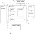
- the control unit or base unit comprises a controller 37.
- the control unit or base unit may further comprise one or more of the above-discussed pumps 31, 32 and a battery 38.
- the controller is optionally connected to a wireless transceiver, which is adapted to transmit and receive data from the remote control 4, and/or other remote units.
- the remote control may provide control data to the controller 37, for remote control of the control unit. Additionally or alternatively, the controller may transmit data about the irrigation procedure to the remote control or any other remote unit.
- the remote control 4 may e.g. be a smart phone or the like.
- the battery 38 may be a rechargeable battery, chargeable through an external battery charger 5. Charging may e.g. occur through inductive charging from the charging station 5, or as direct charging from a connected electric conductor.
- a pump 32 is arranged to pump air through a conduit to the probe for inflation of the inflatable retention member 23.
- different pumps are used for irrigation and inflation.
- a single pump may be used for both purposes.
- the pump 32 is controlled by the controller 37.
- the controller may start and stop the pump, thereby starting and stopping the inflation, and may also possibly control the operating speed of the pump.
- the pump 32 pumps air (or other inflation fluids) through an electrically controllable valve 81 and into the inflatable retention member 23.
- the valve 81 can be controlled by the controller 37 to assume a fully opened state and a fully closed state, and preferably also intermediate states. In an embodiment, the valve is continuously controllable between any state between the fully closed and opened states. When opened, the valve releases air from the inflatable retention member 23 into the ambient atmosphere, for deflation of the inflatable retention member.
- the controller 37 is arranged to determine an inflation flow rate into the inflatable retention member from the electrically operated pump 32, and a deflation flow rate out from the inflatable retention member through the electrically operated valve 81, to continuously determine an inflation fluid volume based on the inflation flow rate, a deflation fluid volume based on the deflation flow rate, and to continuously determine a present fluid volume in the inflatable retention member as the inflation fluid volume reduced by the deflation fluid volume.
- the controller 37 may further control the electrically operated pump 32 and/or the electrically operated valve 81 based on the determined present fluid volume. For example, the controller 37 may be arranged to prohibit operation of the electrically operated pump when the present fluid volume is determined to have reached a volume safety threshold.
- One and the same volume safety threshold may be used for all catheters useable with the irrigation system. However, in case various catheter types are used together with the irrigation system, different volume safety threshold may be determined for each of the catheter types.
- the catheter types may e.g. differ in material used or size of the catheter and/or the inflatable retention member, etc.
- the size of the inflatable retention member generally corresponds to the fluid volume contained in the inflatable retention member.
- a correlation for an exemplary catheter is illustrated in Fig. 7 .
- the correlation between the volume (ml) and diameter (mm) of the inflatable retention member was found to generally follow a log-normal distribution function, where the diameter increases quite rapidly as the volume increases from zero and upwards, but where the increase rate decreases as the volume increases.
- the electrically operated pump may, whenever activated, always be operated at a constant speed, and e.g. supplied by a constant voltage and current. This makes it possible to determine, e.g. by simple experimental measurements, the air flow provided by the electrically operated pump at different balloon pressure levels.
- the electrically operated pump is arranged to operate at a steady state whenever it is operated, i.e. by being supplied by a constant power.
- the pump is generally operated intermittently at binary states, i.e. a steady state "on” state and an "off" state.
- the pump need not be operated at a constant speed or with a steady state power.
- the voltage and the current may also be varied during operation of the pump.
- the system may further comprise a power sensor for determining at least one of a current and a voltage supplied to the electrically operated pump.
- a power sensor for determining at least one of a current and a voltage supplied to the electrically operated pump.
- Fig. 9 a relationship between current (mA) and Flow (L/min) for an exemplary pump is illustrated.
- the controller may then be arranged to determine the inflation flow rate based on the current and/or voltage supplied to the electrically operated pump, based on input from the power sensor.
- the relationship between the airflow and the power, at various counter pressure levels, can again easily be determined experimentally.
- the electrically operated valve may, whenever activated, always be fully opened.
- the electrically operated valve may be operated intermittently between a fully closed state and a fully opened state. This makes it possible to determine, e.g. by simple experimental measurements, the air flow provided through the electrically operated valve when in an open state at different balloon pressure levels.
- Inflation of the inflatable retention member may be performed in various ways.
- inflation is started at S1, e.g. by the user pushing a control element, such as a button or key.
- a volume safety level is determined.
- step S4 a selected volume level may then be obtained, e.g. through input from a user interface.
- All of the steps S2-S4 are optional, and one or more of these steps may be omitted.
- step S5 a present fluid volume is calculated, based on the pressure, the operation time of the electrically operated pump and valve, etc, as discussed in the foregoing.
- step S7 If activation of deflation control has been detected, it is determined in step S7 whether the present fluid volume is greater than zero, and if so, the valve is opened in step S8 for release of air from the inflatable retention element.
- step S10 if it is determined that there is no activation of a deflation control, the valve is closed or maintained closed, step S10, and it is then determined whether a control element for inflation has been activated, step S11.
- step S11 If it is determined in step S11 that there is no activation of any inflation control element, the process may return to step S5.
- the process may be repeated and iterated continuously until the irrigation procedure has been ended.
- step S11 may be performed prior to step S6, step S12 may be performed earlier in the process, such as immediately following step S5, etc.
- the inflation flow rate and deflation flow rate could be determined as estimated in various ways.
- the irrigation system could also be used for other purposes than rectal or transanal irrigation, such as other forms of irrigation, or for other medical procedures. Such and other obvious modifications must be considered to be within the scope of the present invention, as it is defined by the appended claims. It should be noted that the above-mentioned embodiments illustrate rather than limit the invention, and that those skilled in the art will be able to design many alternative embodiments without departing from the scope of the appended claims.
Landscapes
- Health & Medical Sciences (AREA)
- Life Sciences & Earth Sciences (AREA)
- Heart & Thoracic Surgery (AREA)
- Biomedical Technology (AREA)
- Anesthesiology (AREA)
- Hematology (AREA)
- Engineering & Computer Science (AREA)
- Animal Behavior & Ethology (AREA)
- General Health & Medical Sciences (AREA)
- Public Health (AREA)
- Veterinary Medicine (AREA)
- Child & Adolescent Psychology (AREA)
- Biophysics (AREA)
- Pulmonology (AREA)
- Infusion, Injection, And Reservoir Apparatuses (AREA)
Priority Applications (2)
| Application Number | Priority Date | Filing Date | Title |
|---|---|---|---|
| EP23202446.3A EP4537866A1 (fr) | 2023-10-09 | 2023-10-09 | Système d'irrigation à commande de gonflage améliorée |
| PCT/EP2024/077872 WO2025078266A1 (fr) | 2023-10-09 | 2024-10-03 | Système d'irrigation à commande de gonflage améliorée |
Applications Claiming Priority (1)
| Application Number | Priority Date | Filing Date | Title |
|---|---|---|---|
| EP23202446.3A EP4537866A1 (fr) | 2023-10-09 | 2023-10-09 | Système d'irrigation à commande de gonflage améliorée |
Publications (1)
| Publication Number | Publication Date |
|---|---|
| EP4537866A1 true EP4537866A1 (fr) | 2025-04-16 |
Family
ID=88297240
Family Applications (1)
| Application Number | Title | Priority Date | Filing Date |
|---|---|---|---|
| EP23202446.3A Pending EP4537866A1 (fr) | 2023-10-09 | 2023-10-09 | Système d'irrigation à commande de gonflage améliorée |
Country Status (2)
| Country | Link |
|---|---|
| EP (1) | EP4537866A1 (fr) |
| WO (1) | WO2025078266A1 (fr) |
Citations (12)
| Publication number | Priority date | Publication date | Assignee | Title |
|---|---|---|---|---|
| US20060114148A1 (en) | 2004-11-30 | 2006-06-01 | Pillai Unnikrishna S | Robust optimal shading scheme for adaptive beamforming with missing sensor elements |
| EP2683424A2 (fr) | 2011-03-10 | 2014-01-15 | Di Martino, Renato | Appareil de réalisation d'irrigations transanales |
| US20140052063A1 (en) | 2011-11-16 | 2014-02-20 | Convatec Technologies, Inc. | Apparatus for preventing over inflation of the retention balloon in medical catheters and airway devices |
| WO2014154635A1 (fr) | 2013-03-28 | 2014-10-02 | Dentsply Ih Ab | Agencement de couplage de cathéter |
| US9138516B2 (en) | 2010-02-11 | 2015-09-22 | Medela Holding Ag | Apparatus and method for recognizing couplings between two system components |
| US20150335529A1 (en) | 2013-06-03 | 2015-11-26 | Dentsply International Inc. | Cylindrical collapsible container |
| WO2016095929A1 (fr) | 2014-12-19 | 2016-06-23 | Coloplast A/S | Système d'irrigation anale et/ou stomiale et procédé de commande d'un tel système |
| US20160193403A1 (en) | 2012-06-29 | 2016-07-07 | Dentsply International Inc. | Motorized irrigation system |
| EP3338827A1 (fr) | 2016-12-22 | 2018-06-27 | Dentsply IH AB | Système de cathéter motorisé à commande de gonflage améliorée |
| US20190224402A1 (en) * | 2016-07-08 | 2019-07-25 | Hollister Incorporated | Wireless electronic pump design for a body cavity irrigation device |
| WO2020142185A1 (fr) | 2019-01-04 | 2020-07-09 | Hollister Incorporated | Connecteurs de tubes intelligents pour systèmes d'irrigation de cavité corporelle et connecteurs de tubes coaxiaux |
| US20220143372A1 (en) * | 2019-04-11 | 2022-05-12 | Coloplast A/S | Control of balloon size in bowel irrigation system |
-
2023
- 2023-10-09 EP EP23202446.3A patent/EP4537866A1/fr active Pending
-
2024
- 2024-10-03 WO PCT/EP2024/077872 patent/WO2025078266A1/fr active Pending
Patent Citations (13)
| Publication number | Priority date | Publication date | Assignee | Title |
|---|---|---|---|---|
| US20060114148A1 (en) | 2004-11-30 | 2006-06-01 | Pillai Unnikrishna S | Robust optimal shading scheme for adaptive beamforming with missing sensor elements |
| US9138516B2 (en) | 2010-02-11 | 2015-09-22 | Medela Holding Ag | Apparatus and method for recognizing couplings between two system components |
| EP2683424A2 (fr) | 2011-03-10 | 2014-01-15 | Di Martino, Renato | Appareil de réalisation d'irrigations transanales |
| US20140052063A1 (en) | 2011-11-16 | 2014-02-20 | Convatec Technologies, Inc. | Apparatus for preventing over inflation of the retention balloon in medical catheters and airway devices |
| US20160193403A1 (en) | 2012-06-29 | 2016-07-07 | Dentsply International Inc. | Motorized irrigation system |
| WO2014154635A1 (fr) | 2013-03-28 | 2014-10-02 | Dentsply Ih Ab | Agencement de couplage de cathéter |
| US20150335529A1 (en) | 2013-06-03 | 2015-11-26 | Dentsply International Inc. | Cylindrical collapsible container |
| WO2016095929A1 (fr) | 2014-12-19 | 2016-06-23 | Coloplast A/S | Système d'irrigation anale et/ou stomiale et procédé de commande d'un tel système |
| US20190224402A1 (en) * | 2016-07-08 | 2019-07-25 | Hollister Incorporated | Wireless electronic pump design for a body cavity irrigation device |
| EP3338827A1 (fr) | 2016-12-22 | 2018-06-27 | Dentsply IH AB | Système de cathéter motorisé à commande de gonflage améliorée |
| US10569009B2 (en) * | 2016-12-22 | 2020-02-25 | Dentsply Ih Ab | Motorized catheter system with improved inflation control |
| WO2020142185A1 (fr) | 2019-01-04 | 2020-07-09 | Hollister Incorporated | Connecteurs de tubes intelligents pour systèmes d'irrigation de cavité corporelle et connecteurs de tubes coaxiaux |
| US20220143372A1 (en) * | 2019-04-11 | 2022-05-12 | Coloplast A/S | Control of balloon size in bowel irrigation system |
Also Published As
| Publication number | Publication date |
|---|---|
| WO2025078266A1 (fr) | 2025-04-17 |
Similar Documents
| Publication | Publication Date | Title |
|---|---|---|
| US10569009B2 (en) | Motorized catheter system with improved inflation control | |
| US10569008B2 (en) | Motorized irrigation system | |
| AU2017327678B2 (en) | Motorized irrigation system with improved flow control | |
| EP4537866A1 (fr) | Système d'irrigation à commande de gonflage améliorée | |
| EP4537865A1 (fr) | Système d'irrigation à régulation de débit améliorée |
Legal Events
| Date | Code | Title | Description |
|---|---|---|---|
| PUAI | Public reference made under article 153(3) epc to a published international application that has entered the european phase |
Free format text: ORIGINAL CODE: 0009012 |
|
| STAA | Information on the status of an ep patent application or granted ep patent |
Free format text: STATUS: THE APPLICATION HAS BEEN PUBLISHED |
|
| AK | Designated contracting states |
Kind code of ref document: A1 Designated state(s): AL AT BE BG CH CY CZ DE DK EE ES FI FR GB GR HR HU IE IS IT LI LT LU LV MC ME MK MT NL NO PL PT RO RS SE SI SK SM TR |
|
| STAA | Information on the status of an ep patent application or granted ep patent |
Free format text: STATUS: REQUEST FOR EXAMINATION WAS MADE |
|
| 17P | Request for examination filed |
Effective date: 20251014 |