EP4537909A1 - Frein à câble - Google Patents
Frein à câble Download PDFInfo
- Publication number
- EP4537909A1 EP4537909A1 EP24205975.6A EP24205975A EP4537909A1 EP 4537909 A1 EP4537909 A1 EP 4537909A1 EP 24205975 A EP24205975 A EP 24205975A EP 4537909 A1 EP4537909 A1 EP 4537909A1
- Authority
- EP
- European Patent Office
- Prior art keywords
- rope
- brake
- loop
- rope brake
- pivot axis
- Prior art date
- Legal status (The legal status is an assumption and is not a legal conclusion. Google has not performed a legal analysis and makes no representation as to the accuracy of the status listed.)
- Pending
Links
Images




Classifications
-
- A—HUMAN NECESSITIES
- A62—LIFE-SAVING; FIRE-FIGHTING
- A62B—DEVICES, APPARATUS OR METHODS FOR LIFE-SAVING
- A62B1/00—Devices for lowering persons from buildings or the like
- A62B1/06—Devices for lowering persons from buildings or the like by making use of rope-lowering devices
- A62B1/14—Devices for lowering persons from buildings or the like by making use of rope-lowering devices with brakes sliding on the rope
-
- A—HUMAN NECESSITIES
- A63—SPORTS; GAMES; AMUSEMENTS
- A63B—APPARATUS FOR PHYSICAL TRAINING, GYMNASTICS, SWIMMING, CLIMBING, OR FENCING; BALL GAMES; TRAINING EQUIPMENT
- A63B29/00—Apparatus for mountaineering
- A63B29/02—Mountain guy-ropes or accessories, e.g. avalanche ropes; Means for indicating the location of accidentally buried, e.g. snow-buried, persons
Definitions
- the present invention relates to a cable brake according to the preamble of claim 1.
- Such rope brakes are designed for use with a textile safety rope used to secure a belayed person from falling while being belayed.
- the rope brake brakes the safety rope and thereby reduces the force transferred from the safety rope to the belaying person. This is particularly advantageous when the belaying person is lighter than the belayed person.
- Such rope brakes enable rope teams between two people of different weights, so that the heavier person can also be belayed by the lighter person.
- Such rope brakes are particularly important when climbing natural or artificial walls, for example when lead climbing.
- the person in front is the belayed person and is usually connected to the safety rope via a suitable harness, so that the leading, belayed person takes the safety rope with them.
- the safety rope is gradually attached to fixed or wall-mounted anchor points, for example in the form of firmly anchored eyelets, using appropriate carabiners.
- the person climbing behind or waiting is the belayer and is located below the belayer.
- the belayer is also connected to the safety rope and gradually lowers it according to the progress of the belayer.
- the belayer usually uses a belay device through which the safety rope is threaded and which is usually attached to a harness that the belayer wears. carries.
- the belay device enables the targeted release of the safety rope during the climbing process.
- the belayer is designed to hold the safety rope using the belay device so that the safety rope is firmly connected to the belaying person via the belay device and the harness.
- the belaying person is ultimately securing the belayed person with their body weight. If a heavier belayed person falls, there is a chance that the belaying person will not be able to hold the safety rope, which is then subject to high tensile force, despite the belay device. There is also a chance that the lighter belaying person will be lifted and/or pulled against the wall by the tensile force of the held safety rope, which puts the belaying person at risk of injury.
- a rope brake is also used.
- This brake is detachably attached to one of the belay points, usually the closest belay point to the person being belayed.
- the belay point to which the brake is attached is located between the belayed person and the person providing the belay.
- the safety rope is fed through the brake.
- the brake creates a frictional force on the safety rope, which removes tensile force from the loaded safety rope and transfers it to the stationary belay point, for example, on the wall.
- the tensile force arriving at the belaying person via the safety rope is then reduced accordingly.
- the belaying person can more easily hold the safety rope in the belay device, which is subject to reduced tensile force.
- the reduced tensile force is usually no longer sufficient to secure the To lift a person and pull them against the wall.
- a key feature of this type of rope brake is that in the event of a fall, the rope brake only slows the safety rope, but does not block it. This means that only a portion of the force acting on the safety rope is absorbed by the rope brake, while the remaining force is absorbed by the belayer. This is the only way the belayer can safely lower the fallen person hanging from the safety rope.
- a conventional rope brake which has a V-shaped brake slot through which the safety rope is fed.
- the safety rope When tensile load is applied, the safety rope is pulled into the brake slot, which greatly increases friction between the safety rope and the rope brake due to clamping.
- this conventional rope brake In order for this conventional rope brake to function properly, it requires a comparatively high dead weight. If the rope brake is too light, it will trigger even at the slightest resistance or friction, so that the safety rope is pulled into the brake slot, preventing further climbing. On the other hand, the braking effect of such a V-shaped brake slot cannot be made arbitrarily strong. If the brake slot is designed too aggressively, the lowering of the belayed person will be jerky or the rope brake will constantly trigger incorrectly.
- the contour of the brake slot can cause the safety rope to get caught on it and take the rope brake with it. As a result, the safety rope is braked, which hinders the climbing process. It's also possible that, after a fall by the belayed person, the safety rope becomes so jammed in the brake slot that the conventional rope brake can no longer be released without tools and/or without damaging the safety rope. As a result, the supported belayed person cannot be easily lowered and cannot continue climbing.
- a generic rope brake is from the DE 10 2021 002 712 B3 known and is configured such that it can be releasably attached to a securing point located between the secured person and the securing person.
- the rope brake has a rotationally symmetrical guide element for guiding the safety rope, as well as a bell crank that has a fastening section and a braking section and is pivotally mounted about a pivot axis.
- the rope brake is configured such that the safety rope can be passed between the guide element and the bell crank.
- the fastening section is designed to attach the rope brake to the respective securing point.
- the known rope brake is also equipped with a stop that limits the pivoting movement of the bell crank.
- the stop is positioned so that the distance between the bell crank and the guide element is always greater than the diameter of the safety rope.
- the bell crank pivots as far as it will go, so that the safety rope is deflected both over the braking section and over the guide element in order to create the desired braking effect through friction of the safety rope on both the braking section and the guide element.
- the stop and the selected clearance between the bell crank and the guide element in the known rope brake ensure that the safety rope cannot become jammed between the braking section and the guide element.
- the braking effect in the known rope brake is not achieved through clamping, but only through friction.
- the disadvantage of the known rope brake is that due to the stop and the selected spacing between the bell crank and the guide element, the rope brake can only be used with safety ropes whose diameter is smaller than the distance between the bell crank and the guide element. The diameter of the safety rope must not be too small either, so that a sufficient braking effect can be generated through friction.
- the well-known rope brake works best with a standard safety rope that has a standard diameter. A diameter of 9 mm ⁇ 0.5 mm, for example, can be assumed to be the standard for safety ropes. Therefore, well-known rope brakes generally work well in a diameter range of 9-10 mm, but less so above and below.
- the safety rope can slide along the guide element and/or along an additional element while climbing, resulting in a certain static friction which, depending on the speed at which the safety rope is pulled through the rope brake, can take the rope brake with it more or less and can be felt haptically as additional ballast by the belayed person climbing ahead.
- the present invention addresses the problem of providing an improved or at least a different embodiment for a rope brake of the type mentioned above, which is characterized in particular in that it can also be used with different safety ropes that differ from one another in terms of different cross-sections or diameters.
- the invention is based on the general idea of dispensing with a stop to ensure a minimum distance between the braking section and the guide element and of coordinating the bell crank and the guide element in such a way that distances between the bell crank and the guide element can also be set that are smaller than the diameter of the safety rope.
- the safety rope can also be clamped between the braking section and the guide section, so that the braking effect can also be generated by clamping the safety rope.
- the safety rope between the braking section and the guide element is elastically deformed, in particular elastically squeezed, which significantly increases the pressure of the safety rope against the braking section and the guide element, so that a particularly strong friction effect and thus a correspondingly high braking effect can be achieved.
- the guide element be designed as a guide roller that is mounted to rotate about a rotational axis, and that the deflection lever and the guide roller are coordinated with one another in such a way that the safety rope, which is loaded by a fall of the secured person, is clamped between the braking section and the guide roller and is thereby braked - i.e. by the clamping - without blocking.
- the rope brake according to the invention can therefore also be used with safety ropes of different diameters, which results in greater flexibility in the use of the rope brake.
- a sufficient braking effect can be achieved by the clamping even when a safety rope is used that is not a standard safety rope and does not have a standard diameter.
- the rope brake according to the invention therefore operates without stops and therefore also functions with safety ropes that have a have a diameter that is smaller or larger than the standard diameter.
- the inventive proposal to design the guide element as a guide pulley improves climbing.
- the rotatable guide pulley reduces the friction of the safety rope within the rope brake and thereby reduces interactions between the rope brake and the safety rope during normal climbing.
- the improved guidance of the safety rope is also advantageous in the event of a fall in order to achieve optimal effectiveness of the rope brake.
- the braking section presses the safety rope against the guide pulley, which unwinds with the movement of the safety rope and thus generates essentially no friction between the safety rope and the guide pulley. In this case, the braking effect is generated by the friction between the braking section and the safety rope, which is, however, comparatively large due to the clamping or crushing.
- the guide roller can have a radially outer guide contour that interacts with the safety rope or against which the safety rope comes into contact.
- This radial outer contour can be cylindrical in a simple embodiment.
- the radial outer contour can be groove-shaped and, in particular, have a concave This improves the guiding effect of the guide pulley, particularly in the event of a fall, while at the same time largely preventing plastic deformation or damage to the safety rope caused by the clamping process. It is clear that such a groove or groove limits the minimum usable rope diameter to common, reasonably manageable rope diameters.
- a “configuration” is synonymous with a “design” and/or “arrangement”, so that the phrase “configured so that” is synonymous with the phrase “designed and/or arranged so that”.
- the bell crank and the guide element can be coordinated so that the bell crank can pivot past the guide element when the safety rope is missing.
- This embodiment can only be used with safety ropes that have a minimum diameter, which can, however, be significantly smaller than the standard diameter.
- the guide element can be designed as a fixed cylindrical guide pin extending parallel to the pivot axis of the bell crank. In the event of a fall, such a fixed guide pin causes the safety rope to be braked by friction at both the braking section and the guide pin, which is particularly effective.
- the pivot axis of the bell crank can run parallel to the rotation axis of the guide roller. This results in a particularly simple and functionally reliable design.
- the bell crank and the guide pulley can be coordinated in such a way that the safety rope can roll along the guide pulley during climbing without touching the bell crank. This results in minimal rolling friction during climbing, so that the rope safety device is barely noticeable to the belayed person.
- the deflection lever and the guide roller are coordinated with one another in such a way that in the event of a fall, a wrap angle of less than 180°, preferably less than 150°, is set at the guide roller and at the braking section. This means that the safety rope is subjected to relatively low mechanical stress in the event of a fall, which supports its longevity and long-term functional reliability.
- the braking section can be inclined relative to the fastening section toward the guide pulley. This measure supports a compact design, a rapid and precise response of the rope safety device in the event of a fall, and can create sufficient clearance for the safety rope to pass through the rope brake with low friction during normal climbing.
- a preferred embodiment is one in which the rope brake has a base plate from which the guide element protrudes and on which the bell crank is pivotally mounted.
- the rope brake can have a cover plate that is adjustable on the base plate between an open position and a closed position. In the open position, the cover plate opens an access through which the safety rope can be inserted into the rope brake between the guide element and the bell crank at right angles to the longitudinal direction of the rope. In the closed position, the cover plate closes this access so that the safety rope inserted into the rope brake cannot be removed from the rope brake at right angles to the longitudinal direction of the rope. This measure supports safe operation of the rope brake during use with the safety rope.
- the rope brake can have a bearing pin protruding from the base plate, on which the bell crank and the cover plate are pivotably mounted about a common pivot axis. This results in a compact design for the rope brake.
- the rope brake can have a cooperating with the cover plate Have a locking element that can be adjusted between an unlocked position and a secured position. In the unlocked position, the locking element allows the cover plate to be moved from the closed position to the open position. In the secured position, however, the locking element secures or blocks the cover plate in its closed position. Due to this design, the user must first actuate the locking element, in particular manually, in order to then be able to move the cover plate from the closed position to the open position, preferably also manually. This measure can prevent the cover plate from being opened accidentally.
- a bearing pin can also be provided for the guide roller, on which the guide roller is rotatably mounted, in particular via at least one bearing, and which protrudes from the base plate.
- the cover plate can be provided with a positive-locking engagement with this bearing pin in the closed position, so that the bearing pin is also supported on the cover plate. This provides the cable brake with particularly high stability in the closed position.
- fastening section of the bell crank has a fastening opening for attaching a carabiner, with which the rope brake can be attached to the respective securing point. This creates a particularly simple and cost-effective embodiment.
- the fastening section of the bell crank can be equipped with a fastening bolt on which a holding element is held, with which the cable brake can be secured at the respective securing point
- the retaining element provides greater flexibility for the use of the rope brake at differently designed securing points.
- the holding element can be a textile holding element.
- a textile holding element is characterized by high flexibility and low weight, making it versatile. Particularly in the event of a fall, a textile holding element can allow relative movement between the rope brake and the respective securing point, thereby preventing damage to the safety rope in the event of a fall.
- the fastening bolt can be detachably attached to the bell crank or the fastening section.
- the fastening bolt can be configured as a threaded bolt that is screwed to the fastening section.
- Such a detachable fastening bolt is particularly advantageous in conjunction with a textile retaining element, since it allows the retaining element to be replaceably attached to the rope brake.
- the textile retaining element is subject to greater wear than other components of the rope brake. Due to the detachably attached fastening bolt, the retaining element can be replaced multiple times during the service life of the rope brake.
- the retaining element to be a textile rope or band having two end sections and a middle section connecting the two end sections.
- the two end sections are sewn to the middle section in such a way that two loops are formed, spaced apart from each other.
- One loop now wraps around the fastening bolt, while the other loop can be used to attach the rope brake to the respective securing point.
- sewn retaining elements are characterized by great robustness and low production costs.
- the retaining element can also be a loop made of a textile rope or tape that wraps around the fastening bolt and with which the rope brake can be attached to the respective securing point.
- a loop is self-contained, i.e., virtually endless. Using such a loop as a retaining element allows for particularly high flexibility in using the rope brake at a wide variety of securing points.
- the fastening bolt is arranged on the fastening section so that its distance from the pivot axis is adjustable and can be fixed in at least two different positions that differ from one another due to different distances from the pivot axis.
- the distance of the fastening bolt from the pivot axis defines the effective lever arm of the fastening section, which presses the braking section against the safety rope in the event of a fall.
- This lever arm determines the force that can be removed from the safety rope through friction with the help of the rope brake in the event of a fall.
- the lever arm and thus the aforementioned distance thus determines the size of the weight difference between the secured person and the belaying person, which can be compensated for with the help of the rope brake.
- the adjustability of the fastening bolt which allows different positions with different distances from the pivot axis to be set, thus enables the rope brake to be adapted to different weight differences between the belaying person and the belayed person. This results in a particularly wide range of uses for the rope brake.
- the fastening section can be transverse to the pivot axis
- the fastening bolt is adjustable transversely to the pivot axis, whereby the distance between the fastening bolt and the pivot axis can be varied.
- the fastening bolt can now be fixed in the respective position on the fastening section, whereby the respectively set distance and the resulting lever arm are fixed.
- the two longitudinal ends of the elongated hole define two end positions for the fastening bolt, in which the fastening bolt can be fixed to the fastening section.
- the fastening bolt can also be configured such that it can be fixed in any intermediate position between the two end positions, so that virtually any number of positions for the locking bolt can be set and fixed, which differ in terms of different distances from the pivot axis.
- the fastening section can have, in addition to the fastening bolt, an adjusting bolt which preferably extends parallel to the fastening bolt and is wrapped around by the loop that forms the holding element.
- the adjusting bolt is arranged on the fastening section at a different distance from the pivot axis than the fastening bolt.
- the adjusting bolt can expediently be arranged relative to the fastening bolt such that the loop can be transferred into a first loop position and a second loop position. In the first loop position, the loop is guided past the adjusting bolt on a side of the adjusting bolt facing the pivot axis. In the second loop position, the loop is guided past the adjusting bolt on a side of the adjusting bolt facing away from the pivot axis.
- the adjustment bolt can be designed to be detachable, allowing a third loop position to be set, in which the loop wraps around the adjustment bolt. This essentially creates a third effective lever arm, since in the third loop position, the loop rests on the adjustment bolt on one side and on the fastening bolts on the other side in the event of a fall, creating a central lever arm that lies between those of the first and second loop positions.
- the fastening section of the bell crank can have a first adjusting bolt and a second adjusting bolt, each of which is at a different distance from the pivot axis than the fastening bolt.
- the two adjusting bolts can expediently extend parallel to the fastening bolt.
- the first adjusting bolt is arranged closer to the pivot axis than the second adjusting bolt.
- the adjusting bolts are arranged relative to the fastening bolt such that the loop can be transferred into a first loop position, a second loop position, and a third loop position. In the first loop position, the loop is guided past the first adjusting bolt on a side facing the pivot axis.
- the loop In the second loop position, the loop is guided past the second adjusting bolt on a side facing away from the pivot axis. In the third loop position, the loop is guided between the first adjusting bolt and the second adjusting bolt.
- different effective lever arms can be set by means of the different loop positions, whereby the rope brake can be easily adapted to different Weight differences between the secured person and the people being secured can be adjusted.
- a suitable design is one in which the rope brake has a spring element that interacts with the bell crank to drive the braking section away from the guide element. This ensures smooth, largely unhindered passage of the safety rope through the rope brake during normal climbing.
- a cable brake 1 comprises a rotationally symmetrical guide element 2 and a deflection lever 3, which has a fastening section 4 and a braking section 5 and which is pivotally mounted about a pivot axis 6.
- the rope brake 1 is designed for use with a textile safety rope 7, of which the Figures 1 to 9 only a small section is shown in each case.
- the safety rope 7 serves to secure a secured person 8, who is indicated by a circle in the figures, against a fall from a height, wherein the securing is carried out by a belaying person 9, who is also represented by a circle.
- the rope brake 1 can be detachably fastened to a securing point 10 which, when the safety rope 7 is in use, is located between the secured person 8 and the belaying person 9.
- a securing point 10 can be fixed or anchored to a natural or artificial wall 11.
- the rope brake 1 can usually be attached to the respective securing point 10 by means of a carabiner.
- the guide element 2 serves to guide the safety rope 7.
- the safety rope 7 can be passed or is passed through the rope brake 1 between the guide element 2 and the bell crank 3.
- the fastening section 4 serves to fasten the rope brake 1 to the respective securing point 10, whereby appropriate securing elements, such as a carabiner or the like, can be used.
- the safety rope 7 is connected on the one hand to the belayed person 8 and on the other hand to the belaying person 9. These connections are indicated in the figures by broken lines.
- the belayed person 8 goes ahead and takes the safety rope 7 with him.
- the belaying person 9 lets the progress of the secured person 8, the rope 7 in such a way that just enough free rope length is available for the secured person 8 to move freely. In this way, the free rope length is as short as possible in the event of a fall of the secured person 8, so that the securing effect of the safety rope 7 sets in quickly.
- the securing point 10, to which the rope brake 1 is attached is located - in contrast to the greatly simplified representation of the Figures 1 to 9 - when climbing between the belayed person 8 and the belaying person 9, who is located below the belayed person 8. This is usually the belay point 10 closest to the belaying person 9.
- the attachment of the rope brake 10 to the respective belay point 10 is indicated in the figures by a dashed line.
- FIGs 1 and 2 is a condition that occurs during proper climbing, i.e. when the safety rope 7 is largely unloaded.
- the rope brake 1 hangs downwards due to its own weight at the respective securing point 10 in the direction of the belaying person 9.
- Figures 3 to 9 show, however, a loaded state of the safety rope 7, which occurs primarily as a result of a fall of the secured person 8.
- the rope brake 1 is pulled upwards, whereby it then extends upwards from the respective securing point 10 in the direction of the secured person 8.
- This kinematics results from the fact that the securing person 9 is usually positioned further away from the wall 11 than the secured person 8 climbing on or in the wall 11. This causes the safety rope 7 to be deflected at the guide element 7, which pulls the rope brake 1 upwards as a whole when the safety rope 7 is subjected to an upward tensile load via the guide element 2.
- the bell crank 3 and the guide element 2 are coordinated in such a way that the loaded safety rope 7 is clamped between the braking section 5 and the guide element 2 and is thereby braked.
- the clamping does not correspond to a blocking, since the safety rope 7 can move against the frictional force relative to the rope brake 1 even in the clamped state.
- the clamping results from the fact that the braking section 5 can approach the guide element 2 when the bell crank 3 is pivoted, so that the distance between the braking section 5 and the guide element 2 is smaller than a diameter 12 of the safety rope 7.
- the clamping causes an elastic deformation of the safety rope 7.
- FIG. 3 to 9 A state is shown in which the tension in the safety rope 7 has moved the rope brake 1 upwards relative to the respective securing point 10 to which the rope brake 1 is attached.
- the bell crank 3 has pivoted far enough that the braking section 5 has approached the guide element 2, but not yet far enough for clamping to occur. With greater tensile load, the bell crank 3 can pivot further clockwise, allowing the braking section 5 to approach the guide element 2 further, until the safety rope 7 becomes clamped and crushed between the braking section 5 and the guide element 2.
- the configuration of the bell crank 3 and guide element 2 is expediently selected such that the bell crank 5 can be pivoted until it rests against the guide element 2 when the safety cable 7 is missing, or can be pivoted past the guide element 2.
- the bell crank 3 and guide element 2 can be coordinated with one another such that the guide element 2 limits the pivoting of the bell crank 3 by the braking section 5 coming into contact with the guide element 2 when the safety cable 7 is missing.
- the guide element 2 forms a kind of stop that limits the pivoting of the The deflection lever 3 is limited when the braking section 5 comes into contact with the guide element 2 forming the stop in the absence of the safety cable 7.
- the guide element 2 is designed as a guide roller 13, which is mounted for rotation about a rotation axis 14.
- the rotation axis 14 extends parallel to the pivot axis 6.
- the guide roller 13 has a groove-shaped outer contour radially outward with respect to its rotation axis 14, into which the safety cable 7 dips, thus ensuring a secure guiding effect.
- the rocker arm 3 and the guide roller 13 are matched to each other so that when climbing according to Figures 1 and 2 the safety rope 7 can unwind along the guide roller 13 without touching the bell crank 3.
- the bell crank 3 and the guide roller 13 can be coordinated so that in the event of a fall, Figures 3 to 9 on the guide roller 13 and on the braking section 5, a wrap angle of less than 180°, preferably less than 150°, in particular less than 135°, is set.
- the braking section 5 is inclined towards the guide roller 13 relative to the fastening section 4.
- a preferred angle of inclination of 30° is shown. This angle of inclination can preferably be in an angular range of 15° to 45°.
- the cable brake 1 has a base plate 15 from which the guide element 2 protrudes or the guide roller 13 is rotatably mounted.
- the deflection lever 3 is also pivotally mounted on the base plate 15.
- the cable brake 1 has a Figures 2 and 6 to 9 recognizable cover plate 16, which for explanatory purposes is shown in Figure 1 drawn with a broken line and in the Figures 3 to 5
- the cover plate 16 is fixed to the base plate 15 between a Figure 1 recognizable open position and one in the Figures 2 and 6 to 9 shown closed position. In the open position, the cover plate 16 releases according to Figure 1 an access 17 is free, through which the safety rope 7 can be inserted into the rope brake 1 transversely to the longitudinal direction of the rope between the guide element 2 and the deflection lever 3.
- the cable brake 1 can have a bearing pin 18 projecting from the base plate 15, on which the deflection lever 3 and the cover plate 16 are mounted about a common pivot axis 6. Furthermore, the cable brake 1 can have a further bearing pin 19 projecting from the base plate 15, on which the guide roller 3 is rotatably mounted.
- at least one bearing 20 can be provided, which can be a plain bearing or a roller bearing, in particular as a ball bearing.
- two such bearings 20 can also be mounted axially adjacent to the bearing pin 19 in order to support the guide roller 13.
- the cover plate 16 can be configured such that, in the closed position, it positively engages with the additional bearing pin 19, such that, in the closed position of the cover plate 16, the bearing pin also supports the cover plate 16 in a force-transmitting manner. In the open position, the cover plate 16 is released from this bearing pin 19 to open the access 17.
- the cable brake 1 can also have a manually operable securing element 21 that interacts with the cover plate 16.
- the securing element 21 is adjustable between an unlocked position, in which the securing element 21 enables adjustment, in particular pivoting, of the cover plate 16 from the closed position to the open position, and a securing position, in which the securing element 21 secures or blocks the cover plate 16 in its closed position.
- the securing element 21 can be spring-loaded into its securing position, such that when the cover plate 16 is adjusted to its closed position, the securing element 21 is automatically returned to its securing position.
- FIG 8 a particularly simple embodiment of the rope brake 1 is shown, which is characterized in that the fastening section 4 of the bell crank 3 has a fastening opening 22 which is configured such that a carabiner 23 can be fastened to the rope brake 1 through this fastening opening 22, with the aid of which the rope brake 1 can be fastened to the respective securing point 10.
- a fastening bolt 24 is provided on the fastening section 4 of the bell crank 3, which bolt expediently extends parallel to the pivot axis 6.
- the rope brake 1 is also equipped with a holding element 25, which is held on the fastening bolt 24 and with which the rope brake 1 can be fastened to the respective securing point 10.
- the holding element 25 can be fixed to the respective securing point 10 using a carabiner.
- the holding element 25 can be Figures 1 to 3 and 9 a first opening 26 through which the fastening bolt 24 passes, and a second opening 27 into which, for example, a carabiner can engage.
- the fastening section 4 can expediently have two cheeks 41, which are spaced apart from one another parallel to the pivot axis 6 and which run parallel to one another.
- the two cheeks 41 extend from a central area of the reversing lever 3, through which the pivot axis 6 runs.
- the fastening bolt 24 is supported on both cheeks 41.
- the holding element 25 engages around the fastening bolt 24 between the two cheeks 41.
- Figures 6 and 7 the cheek 41 facing the viewer is omitted. In the Figures 1 to 5 only the cheek 41 facing the viewer is visible. In the isometric view of the Figure 9 Both cheeks 41 are visible. In the Figure 8 In the embodiment shown, however, there are no cheeks.
- the holding element 25 can be configured as desired. Figures 4 to 7 However, preferred embodiments are shown in which the holding element 25 is formed by a textile holding element 25.
- the fastening bolt 24 can be detachably attached to the deflection lever 3.
- the fastening bolt 24 can be connected to the fastening section 4, e.g., to at least one of the both cheeks. This makes it possible to easily replace the retaining element 25.
- the holding element 25 is designed as a textile band 28.
- the holding element 25 can also be designed as a textile rope.
- the following statements regarding the band 28 then also apply accordingly to the rope.
- the band 28 has two end sections 29, 30 and a middle section 31 connecting the two end sections 29, 30.
- the two end sections 29, 30 are sewn to the middle section 31 in such a way that two loops 32 and 33 are formed, which are spaced apart from one another and connected to one another via a web 34.
- the web 34 is formed by the sewn-together sections 29, 30, 31 of the band 28.
- One loop 32 wraps around the fastening bolt 24.
- the rope brake 1 can be attached to the respective securing point 10 using the other loop 33.
- a carabiner can be attached to this other loop 33.
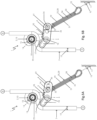
- FIGS 5A and 5B An embodiment is shown in which the fastening bolt 24 is arranged on the fastening section 4 so as to be adjustable with respect to its distance 35 from the pivot axis 6.
- the fastening bolt 24 can be fixed in at least two different positions on the fastening section 4. This allows the effective lever arm of the fastening section 4 to be changed.
- Figures 5A and 5B show two different positions for the fastening bolt 24, which differ from each other by different distances 35 from the pivot axis 6. In Figure 5A the distance 35 is significantly smaller, about half as large as in the Figure 5B .
- the adjustability of the fastening bolt 24 is realized by means of an elongated hole 36 which is formed on the fastening section 4 and through which the fastening bolt 24 passes.
- the elongated hole 36 is aligned in the spacing direction, so that adjusting the fastening bolt 24 within the elongated hole 36 changes the spacing 35.
- the fastening bolt 24 can be fixed within the elongated hole 36 in any desired position on the fastening section 4. This allows the rope brake 1 to be easily adapted to different weight differences between the secured person 8 and the securing person 9.
- the holding element 25 is formed by a loop 37 made of a textile rope or a textile band.
- a textile band loop is preferably used here.
- the loop 37 wraps around the fastening bolt 24 and serves to attach the rope brake 1 to the respective securing point 10.
- a carabiner can be hooked into the loop 37.
- the fastening section 4 of the bell crank 3 is equipped with an adjusting bolt 38 which extends parallel to the fastening bolt 24.
- the arrangement of the adjusting bolt 38 on the fastening section 4 is such that the adjusting bolt 38 and the fastening bolt 24 have different distances from the pivot axis 6. In the example shown here, the distance of the adjusting bolt 38 from the pivot axis 6 is greater than the distance of the fastening bolt 24 from the pivot axis 6.
- the adjusting bolt 38 and the fastening bolt 24 are arranged relative to one another such that the loop 37 is in a Figure 6A shown first loop position and into a Figure 6B shown second loop position.
- FIG. 6A In the first loop position according to Figure 6A the loop 37 is guided past the adjusting bolt 38 on a side of the adjusting bolt 38 facing the pivot axis 6. In the second loop position according to Figure 6B the loop 37, however, is guided past the adjusting bolt 38 on a side of the adjusting bolt 38 facing away from the pivot axis 6.
- Figure 6C also shows an optional third loop position, which is particularly adjustable when the adjusting bolt 38 is designed to be detachable. In the third loop position according to Figure 6C The loop 37 not only wraps around the fastening bolt 24, but also the adjustment bolt 38.
- the three loop positions shown here allow the setting of three different effective lever arms on the fastening section 4 on the same cable brake 1, whereby the force with which the braking section 5 presses the safety cable 7 against the guide element 2 in the case of load can be adjusted or changed.
- a particular advantage here is that the first loop position according to Figure 6A and the second loop position according to Figure 6B can be adjusted without tools.
- the third loop position according to Figure 6C The use of a tool may be necessary, for example, to remove and reinstall the adjustment bolt 38. This allows the rope brake 1 to be easily adjusted to varying weight differences between the secured person 8 and the belaying person 9.
- the fastening section 4 of the bell crank 3 is equipped with a first adjusting bolt 39 and a second adjusting bolt 40, each of which extends parallel to the fastening bolt 24.
- Both adjusting bolts 39, 40 have different distances from the pivot axis 6, which differ from the distance that the fastening bolt 24 has from the pivot axis 6.
- the adjusting bolts 39, 40 are further away from the pivot axis 6 than the fastening bolt 24.
- the first adjusting bolt 39 is arranged closer to the pivot axis 6 than the second adjusting bolt 40.
- the two adjusting bolts 39, 40 and the fastening bolt 24 are arranged relative to one another in such a way arranged on the fastening section 4, that the loop 37 is in a first loop position shown in Figure 7A, in a Figure 7B shown second loop position and into a Figure 7C shown third loop position.
- the loop 37 is guided past the first adjusting bolt 39 on a side facing the pivot axis 6.
- the loop 37 is guided past the second adjusting bolt 40 on a side facing away from the pivot axis 6.
- the third loop position according to Figure 7C The loop 37 is guided between the two adjustment bolts 39, 40.
- the three loop positions each generate a different effective lever arm on the fastening section 4, resulting in different forces under load with which the braking section 5 presses the safety rope 7 against the guide element 2.
- This allows the rope brake 1 to be easily adjusted, without the need for tools, to different weight differences between the secured person 8 and the securing person 9.
Landscapes
- Health & Medical Sciences (AREA)
- General Health & Medical Sciences (AREA)
- Pulmonology (AREA)
- Physical Education & Sports Medicine (AREA)
- Business, Economics & Management (AREA)
- Emergency Management (AREA)
- Braking Arrangements (AREA)
Applications Claiming Priority (1)
| Application Number | Priority Date | Filing Date | Title |
|---|---|---|---|
| DE102023209967.5A DE102023209967B3 (de) | 2023-10-11 | 2023-10-11 | Seilbremse |
Publications (1)
| Publication Number | Publication Date |
|---|---|
| EP4537909A1 true EP4537909A1 (fr) | 2025-04-16 |
Family
ID=93100061
Family Applications (1)
| Application Number | Title | Priority Date | Filing Date |
|---|---|---|---|
| EP24205975.6A Pending EP4537909A1 (fr) | 2023-10-11 | 2024-10-10 | Frein à câble |
Country Status (2)
| Country | Link |
|---|---|
| EP (1) | EP4537909A1 (fr) |
| DE (1) | DE102023209967B3 (fr) |
Cited By (1)
| Publication number | Priority date | Publication date | Assignee | Title |
|---|---|---|---|---|
| DE102025119305B3 (de) | 2025-05-19 | 2026-05-07 | Stephan Chudowski | Vorschaltwiderstand |
Families Citing this family (2)
| Publication number | Priority date | Publication date | Assignee | Title |
|---|---|---|---|---|
| IT202100025394A1 (it) * | 2021-10-04 | 2023-04-04 | Aludesign Spa | Dispositivo multifunzione dotato di una camma di bloccaggio e di una puleggia per una fune di sicurezza |
| US20250032824A1 (en) * | 2023-07-25 | 2025-01-30 | Reg Coates | Apparatus for ascending and descending a line with a load |
Citations (3)
| Publication number | Priority date | Publication date | Assignee | Title |
|---|---|---|---|---|
| DE29520702U1 (de) * | 1995-12-30 | 1996-03-07 | Dahm, Johannes, Dipl.-Ing., 53115 Bonn | Vorrichtung zum Umlenken und Sichern eines Kletterseiles |
| DE102014001695B3 (de) | 2014-02-04 | 2015-06-18 | Andreas Schuhmacher | Seilbremse zur Sicherung von Personen und Gegenständen, insbesondere Personen beim Klettern, die zur Verringerung der Energie im Sturzfall des Kletterers über ein Seil auf den Sichernden einwirkt. |
| DE102021002712B3 (de) | 2021-05-25 | 2022-06-02 | Andreas Schuhmacher | Seilbremse zur Befestigung in einem Sicherungspunkt |
Family Cites Families (4)
| Publication number | Priority date | Publication date | Assignee | Title |
|---|---|---|---|---|
| DE202009014989U1 (de) | 2009-11-04 | 2010-02-25 | Dahm, Johannes | Sicherungsgerät für ein Seil |
| DE102019107587B3 (de) | 2019-03-25 | 2020-03-26 | Fritimi UG (haftungsbeschränkt) | Vorschaltwiderstand für das Klettern |
| DE102021119362A1 (de) | 2020-07-27 | 2022-01-27 | Edelrid Gmbh & Co. Kg | Sicherungsgerät mit einer Seilbremse |
| DE102021102673A1 (de) | 2021-02-04 | 2022-08-04 | Edelrid Gmbh & Co. Kg | Tragbares Seilsicherungsgerät für die Partnersicherung beim Klettern |
-
2023
- 2023-10-11 DE DE102023209967.5A patent/DE102023209967B3/de active Active
-
2024
- 2024-10-10 EP EP24205975.6A patent/EP4537909A1/fr active Pending
Patent Citations (3)
| Publication number | Priority date | Publication date | Assignee | Title |
|---|---|---|---|---|
| DE29520702U1 (de) * | 1995-12-30 | 1996-03-07 | Dahm, Johannes, Dipl.-Ing., 53115 Bonn | Vorrichtung zum Umlenken und Sichern eines Kletterseiles |
| DE102014001695B3 (de) | 2014-02-04 | 2015-06-18 | Andreas Schuhmacher | Seilbremse zur Sicherung von Personen und Gegenständen, insbesondere Personen beim Klettern, die zur Verringerung der Energie im Sturzfall des Kletterers über ein Seil auf den Sichernden einwirkt. |
| DE102021002712B3 (de) | 2021-05-25 | 2022-06-02 | Andreas Schuhmacher | Seilbremse zur Befestigung in einem Sicherungspunkt |
Cited By (1)
| Publication number | Priority date | Publication date | Assignee | Title |
|---|---|---|---|---|
| DE102025119305B3 (de) | 2025-05-19 | 2026-05-07 | Stephan Chudowski | Vorschaltwiderstand |
Also Published As
| Publication number | Publication date |
|---|---|
| DE102023209967B3 (de) | 2025-03-06 |
Similar Documents
| Publication | Publication Date | Title |
|---|---|---|
| DE102023209967B3 (de) | Seilbremse | |
| DE3421098A1 (de) | Zerlegbare und doppeltwirkende seilbremse | |
| DE10011753C2 (de) | Klettergerät für Auf- und Abseilvorgänge | |
| WO2013091625A1 (fr) | Dispositif de retenue, conçu en particulier à des fins d'entraînement | |
| DE19746294A1 (de) | Sicherheitsvorrichtung für Auf- und Abseilvorgänge | |
| EP0859647B1 (fr) | Appareil de levage et d'abaissement a elingue | |
| DE69912739T2 (de) | Selbstkompensierende vorrichtung zur regelung der spannung einer faser | |
| DE102021002712B3 (de) | Seilbremse zur Befestigung in einem Sicherungspunkt | |
| DE3023093C2 (de) | Umlenkbeschlag für einen Sicherheitsgurt | |
| DE2812073A1 (de) | Seilklemme | |
| DE2400198A1 (de) | Sicherheitsbremse | |
| DE102010015572A1 (de) | Fallschutzläufer | |
| DE2850068A1 (de) | Abseil-regelbremse | |
| DE3609824A1 (de) | Personen-abseilgeraet | |
| DE2248748C3 (de) | Bremseinrichtung zum selbsttätigen Abbremsen des einer Spritzpistole zugeführten Faserstrangs | |
| DE2115403C3 (de) | Seilspannungsregler fur Steuer seile | |
| EP0958845A2 (fr) | Dispositif de sécurité pour une corde d'escalade | |
| DE102024120597B4 (de) | Dynamisches Sicherungssystem und Sicherungsgerät | |
| DE102016101649A1 (de) | Auf- und Abseilvorrichtung | |
| EP1159987A2 (fr) | Frein de câble | |
| DE102014100233B3 (de) | Absturzsicherungsgerät | |
| DE4313335C2 (de) | Schlitten mit Fallbremse | |
| DE102024120598A1 (de) | Dynamisches Sicherungssystem und Sicherungsgerät | |
| DE240625C (fr) | ||
| EP0859646B1 (fr) | Treuil pour appareil de levage et d'abaissement |
Legal Events
| Date | Code | Title | Description |
|---|---|---|---|
| PUAI | Public reference made under article 153(3) epc to a published international application that has entered the european phase |
Free format text: ORIGINAL CODE: 0009012 |
|
| STAA | Information on the status of an ep patent application or granted ep patent |
Free format text: STATUS: THE APPLICATION HAS BEEN PUBLISHED |
|
| AK | Designated contracting states |
Kind code of ref document: A1 Designated state(s): AL AT BE BG CH CY CZ DE DK EE ES FI FR GB GR HR HU IE IS IT LI LT LU LV MC ME MK MT NL NO PL PT RO RS SE SI SK SM TR |
|
| STAA | Information on the status of an ep patent application or granted ep patent |
Free format text: STATUS: REQUEST FOR EXAMINATION WAS MADE |
|
| 17P | Request for examination filed |
Effective date: 20251006 |