EP4537962A1 - Outil de tournage et ensemble outil de tournage - Google Patents
Outil de tournage et ensemble outil de tournage Download PDFInfo
- Publication number
- EP4537962A1 EP4537962A1 EP23203543.6A EP23203543A EP4537962A1 EP 4537962 A1 EP4537962 A1 EP 4537962A1 EP 23203543 A EP23203543 A EP 23203543A EP 4537962 A1 EP4537962 A1 EP 4537962A1
- Authority
- EP
- European Patent Office
- Prior art keywords
- side wall
- turning tool
- stiff member
- cutting insert
- insert
- Prior art date
- Legal status (The legal status is an assumption and is not a legal conclusion. Google has not performed a legal analysis and makes no representation as to the accuracy of the status listed.)
- Pending
Links
Images




Classifications
-
- B—PERFORMING OPERATIONS; TRANSPORTING
- B23—MACHINE TOOLS; METAL-WORKING NOT OTHERWISE PROVIDED FOR
- B23B—TURNING; BORING
- B23B27/00—Tools for turning or boring machines; Tools of a similar kind in general; Accessories therefor
- B23B27/14—Cutting tools of which the bits or tips or cutting inserts are of special material
- B23B27/16—Cutting tools of which the bits or tips or cutting inserts are of special material with exchangeable cutting bits or cutting inserts, e.g. able to be clamped
- B23B27/1614—Cutting tools of which the bits or tips or cutting inserts are of special material with exchangeable cutting bits or cutting inserts, e.g. able to be clamped with plate-like cutting inserts of special shape clamped against the walls of the recess in the shank by a clamping member acting upon the wall of a hole in the insert
-
- B—PERFORMING OPERATIONS; TRANSPORTING
- B23—MACHINE TOOLS; METAL-WORKING NOT OTHERWISE PROVIDED FOR
- B23B—TURNING; BORING
- B23B2200/00—Details of cutting inserts
- B23B2200/04—Overall shape
- B23B2200/0447—Parallelogram
-
- B—PERFORMING OPERATIONS; TRANSPORTING
- B23—MACHINE TOOLS; METAL-WORKING NOT OTHERWISE PROVIDED FOR
- B23B—TURNING; BORING
- B23B2200/00—Details of cutting inserts
- B23B2200/08—Rake or top surfaces
- B23B2200/082—Rake or top surfaces with elevated clamping surface
-
- B—PERFORMING OPERATIONS; TRANSPORTING
- B23—MACHINE TOOLS; METAL-WORKING NOT OTHERWISE PROVIDED FOR
- B23B—TURNING; BORING
- B23B2205/00—Fixation of cutting inserts in holders
- B23B2205/12—Seats for cutting inserts
-
- B—PERFORMING OPERATIONS; TRANSPORTING
- B23—MACHINE TOOLS; METAL-WORKING NOT OTHERWISE PROVIDED FOR
- B23B—TURNING; BORING
- B23B2250/00—Compensating adverse effects during turning, boring or drilling
- B23B2250/12—Cooling and lubrication
Definitions
- the present invention refers to a turning tool according to the preamble of claim 1.
- the present invention refers to a turning tool comprising a tool body
- Such a turning tool is already known from EP 4091749 A1 (see for instance Figs. 3 , 5-6 and 10-12), which discloses a turning tool (1) comprising a tool body (3) and a pocket/insert seat (7) for a turning insert (2) provided in an end portion of the tool body.
- the pocket (7) comprises a bottom support surface (8) and first and second pocket side surfaces (9, 10) defining a space for receiving the cutting insert therebetween through an opening to said space defined between front ends of the pocket side surfaces, which are located at and defining part of front end portions of respective side wall sections on which the pocket side surfaces are provided.
- the front end portions of the side wall sections form acute angles with respective outer surfaces of the tool body, adjacent to the pocket.
- the pocket has an open top, which means that the cutting insert, when mounted in the pocket, is not covered by any part thereof, as seen in top view.
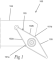
- a conventional turning tool of this type is also schematically shown in Fig 1 of the present application.
- the object of the present invention is to provide a turning tool of the type defined in the introduction, which turning tool is being improved in at least some aspect with respect to such turning tools already known, for instance in respect of wear resistance and tool life, surface finish on the workpiece to be machined, economic and/or environmental aspects.
- the insert seat further comprises a stiff member configured to be rigidly connected by a first end portion thereof to an upper part of the front end portion of the first side wall section and by a second end portion thereof to an upper part of the front end portion of the second side wall section and to extend between said upper parts of the front end portions of the first and second side wall sections over and at a distance to the bottom support surface.
- the stiff member is configured to be rigidly connected by its first and second end portions thereof to and over an entire height of the respective upper parts of the front end portions of the first and second side wall sections, wherein the height of each said upper part is defined as at least 20%, preferably at least 25%, even more preferred at least 30%, of a height of the respective front end portion measured between an upper end thereof and a position therealong located in a plane in which the bottom support surface extends.
- This design and arrangement of the stiff member ensures good stress absorption from and stability to the front end portions.
- the stiff member is configured to be rigidly connected by its first and second end portions thereof to and over at least 20%, preferably at least 25%, even more preferred at least 30%, of a length of respective ones of the first and second inner side wall surfaces, along respective upper portions thereof, wherein the length of each inner side wall surface is measured from the front end to a rear end thereof, in a direction from said front end towards a rear end of the insert seat.
- a front side surface of the stiff member is concavely formed, preferably arc-shaped or at least substantially arc-shaped, as seen in top view, such that a center portion of the front side surface of the stiff member is located closer to a rear end of the insert seat than portions of the front side surfaces located at the first and second end portions of the stiff member.
- the bottom support surface has a symmetrical, or at least substantially symmetrical, shape, it is provided with a hole, especially a threaded hole, in the center thereof, to enable attachement of a said cutting insert by a fastening element, especially a screw, thereto, and the stiff member is arranged between the center hole of the bottom support surface and a rear end of the insert seat such that the center hole is not covered by any part of the stiff member as seen in top view.
- This design of the insert seat and arrangement of the stiff member facilitates an uncomplicated mounting of a cutting insert in the insert seat.
- the tool body is provided with a coolant conveying system, comprising an inlet configured to receive coolant from the machine tool,
- the invention also relates to a turning tool assembly according to the appended independent claim thereof. Realizations of, and advantages with, such a turning tool assembly clearly appears from the above description of embodiments of a turning tool according to the invention and the following description of embodiments of a turning tool as well as a turning tool assembly according to the invention.
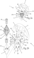
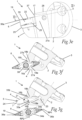
- FIGS. 2a-4f Three different embodiments of a turning tool 1 according to the present invention, each configured to together with a cutting insert 6a-c form a turning tool assembly according to the present invention, are illustrated in Figs 2a-4f .
- the turning tool 1 and turning tool assembly according to the invention will now be described while at the same time making reference to all these drawings.
- Figs 2a-2f and 3a-3g show two slightly different turning tools 1 according to the present invention intended for use with a sharp edged elongated cutting insert 6a-c for fine precision machining, or profiling
- Figs 4a-4f show a turning tool 1 according to the present invention intended for use with a hexagonal cutting insert 6a-c for "roughing" operations.
- the effect of the inventive features are however the same or at least substantially the same for all of these turning tools, which is why the same or corresponding features need not be described in detail for each of these embodiments, but the components and parts described for one of the turning tools, i.e. one of the three embodiments, and indicated with corresponding reference numerals on the other turning tools, have the same or a corresponding function and effect also for the other turning tools, i.e. other embodiments shown, if not otherwise stated.
- the insert seat 5 comprises a bottom support surface 7 and first 8a and second 8b side wall sections extending along at least a part, in the embodiments shown about half, of the bottom support surface 7 on opposite lateral sides thereof.
- the first side wall section 8a comprises a first inner side wall surface 9a and the second side wall section 8b comprises a second inner side wall surface 9b.
- the bottom support surface 7 and the first 9a and second 9b inner side wall surfaces thus together define a pocket-like space 11 for receiving at least a part of the cutting insert 6a-c in said state of use.
- the turning tool 1 further comprises a shim 20, configured to be arranged between the cutting insert 6a-c and the tool body 2 in the state of use, for stabilizing the cutting insert and protecting the tool body.
- the bottom support surface 7 of the insert seat 5 is considered to be defined by a top surface of the shim 20.
- the bottom support surface 7 of the insert seat could also be defined by a permanent bottom surface 7' of the tool body 2 (on which the shim 20 is configured to be mounted if present) in the case no shim is used.
- the insert seat 5 further comprises a stiff member 17 configured to be rigidly connected by a first end portion 18a thereof to an upper part of the front end portion 16a of the first side wall section 8a and by a second end portion 18b thereof to an upper part of the front end portion 16b of the second side wall section 8b and to extend between and rigidly interconnect said upper parts of the front end portions 16a-b of the first 8a and second 8b side wall sections over and at a distance to the bottom support surface 7 and over said space 11.
- the stiff member 17 is formed in one piece with the first 8a and second 8b side wall sections, at the upper parts thereof, as is the case in the embodiments of the turning tool 1 shown.
- a top surface 26 of the stiff member 17 is coherent, i.e. contiguous in one and the same plane, with portions of a top surface 28 of the tool body 2 adjacent to the stiff member 17.
- the stiff member may be formed with a center thereof located at a distance to a portion of the top surface of the tool body adjacent to the rear end 23 of the insert seat, as a "bridge" ( Figs. 2a-3g ), or be coherent with and formed as an extension of said portion of the top surface over the insert seat 5, as a "roof" ( Figs. 4a-4f ).
- the stiff member 17 is to be considered as the part which extends between said upper parts of the first and second side wall sections over the bottom support surface.
- the top surface 22 is considered as the surface on the side of the cutting insert 6a-c seen in a top view (see Figs 2c , 3c and 4c ) and facing away from the bottom support surface 7 when the cutting insert is mounted in the insert seat.
- the bottom surface 25 is in the same way considered as the surface on the side of the cutting insert 6a-c seen in a bottom view (not shown), facing the bottom support surface in the mounted position.
- the turning tool 1 is configured to receive the cutting insert 6a-c in the insert seat 5 in said state of use of the turning tool assembly such that the stiff member 17 configured to extend between said upper parts of the front end portions 16a-b of the first 8a and second 8b side wall sections rigidly interconnects these side wall sections, at the upper parts thereof, over at least a portion of the top surface 22 of the cutting insert 6a-c. More specifically, the stiff member 17 is designed and arranged to cover at least 10%, preferably at least 15%, of the top surface 22 of the cutting insert 6a-c in said state of use, as seen in top view.
- the cutting insert 6b is provided with a first 34a and a second 34b grinded contact surface, configured to be associated with the first 33a and second 33b stop surface, respectively.
- the stop surfaces on the stiff member may also be machined, especially grinded, to achieve a more precise contact between these stop surfaces and the contact surfaces of the cutting insert.
- the cutting insert 6b further comprises a first nose portion 36a and a second opposite nose portion 36b. More specifically, the cutting insert has a symmetrical, rhombic shape (in top view) with two acute nose portions pointing away from each other.
- the first nose portion 36a is provided with a first cutting edge 19 arranged at a transition between the top surface 22 and the circumferential side surface 35 at the first nose portion.
- the second nose portion 36b is correspondingly provided with a second cutting edge arranged at a transition between the top surface 22 and the circumferential side surface 35 at the second nose portion.
- the cutting insert is thus indexable so that the second nose portion may be used as the active nose portion after the first nose porton, and more specifically the first cutting edge 19 thereof, is worn down.
- the invention provides a turning tool and a turning tool assembly having a stronger and stiffer insert seat with respect to insert seats of such tools and assemblies already known. This results especially in a more wear resistant tool and thereby increased tool life, but also imply other positive effects, such as increased performance of the tool as this may more stabily hold a cutting insert in a precise position during a turning operation, which increase the possibilities to achieve a satisfying surface finish of the machined workpiece.
- the stiff member of the turning tool and a turning tool assembly according to the invention imply several other benefits, such as facilitating a more efficient cooling of the tool and insert, support for the insert and load distribution in the cutting insert and turning tool body.
Landscapes
- Engineering & Computer Science (AREA)
- Mechanical Engineering (AREA)
- Milling Processes (AREA)
Priority Applications (3)
| Application Number | Priority Date | Filing Date | Title |
|---|---|---|---|
| EP23203543.6A EP4537962A1 (fr) | 2023-10-13 | 2023-10-13 | Outil de tournage et ensemble outil de tournage |
| CN202480058700.8A CN121843781A (zh) | 2023-10-13 | 2024-09-04 | 车削刀具和车削刀具组件 |
| PCT/EP2024/074694 WO2025078076A1 (fr) | 2023-10-13 | 2024-09-04 | Outil de tournage et ensemble outil de tournage |
Applications Claiming Priority (1)
| Application Number | Priority Date | Filing Date | Title |
|---|---|---|---|
| EP23203543.6A EP4537962A1 (fr) | 2023-10-13 | 2023-10-13 | Outil de tournage et ensemble outil de tournage |
Publications (1)
| Publication Number | Publication Date |
|---|---|
| EP4537962A1 true EP4537962A1 (fr) | 2025-04-16 |
Family
ID=88413362
Family Applications (1)
| Application Number | Title | Priority Date | Filing Date |
|---|---|---|---|
| EP23203543.6A Pending EP4537962A1 (fr) | 2023-10-13 | 2023-10-13 | Outil de tournage et ensemble outil de tournage |
Country Status (3)
| Country | Link |
|---|---|
| EP (1) | EP4537962A1 (fr) |
| CN (1) | CN121843781A (fr) |
| WO (1) | WO2025078076A1 (fr) |
Citations (5)
| Publication number | Priority date | Publication date | Assignee | Title |
|---|---|---|---|---|
| US6769843B2 (en) * | 2001-01-30 | 2004-08-03 | Sandvik Ab | Tool holder having insert seat with flexible side surface |
| US20100316454A1 (en) * | 2007-02-28 | 2010-12-16 | Wolfgang Zitzlaff | Insert seat adapter |
| EP4091749A1 (fr) | 2021-05-20 | 2022-11-23 | AB Sandvik Coromant | Outil tournant de découpage de métal |
| CN219093668U (zh) * | 2022-12-14 | 2023-05-30 | 中国航空工业集团公司金城南京机电液压工程研究中心 | 一种软材料车刀 |
| EP3539696B1 (fr) * | 2018-03-13 | 2023-10-11 | AB Sandvik Coromant | Outil pour le tournage de métal comprenant un canal de refroidissement |
-
2023
- 2023-10-13 EP EP23203543.6A patent/EP4537962A1/fr active Pending
-
2024
- 2024-09-04 CN CN202480058700.8A patent/CN121843781A/zh active Pending
- 2024-09-04 WO PCT/EP2024/074694 patent/WO2025078076A1/fr active Pending
Patent Citations (5)
| Publication number | Priority date | Publication date | Assignee | Title |
|---|---|---|---|---|
| US6769843B2 (en) * | 2001-01-30 | 2004-08-03 | Sandvik Ab | Tool holder having insert seat with flexible side surface |
| US20100316454A1 (en) * | 2007-02-28 | 2010-12-16 | Wolfgang Zitzlaff | Insert seat adapter |
| EP3539696B1 (fr) * | 2018-03-13 | 2023-10-11 | AB Sandvik Coromant | Outil pour le tournage de métal comprenant un canal de refroidissement |
| EP4091749A1 (fr) | 2021-05-20 | 2022-11-23 | AB Sandvik Coromant | Outil tournant de découpage de métal |
| CN219093668U (zh) * | 2022-12-14 | 2023-05-30 | 中国航空工业集团公司金城南京机电液压工程研究中心 | 一种软材料车刀 |
Also Published As
| Publication number | Publication date |
|---|---|
| WO2025078076A1 (fr) | 2025-04-17 |
| CN121843781A (zh) | 2026-04-10 |
Similar Documents
| Publication | Publication Date | Title |
|---|---|---|
| US6050752A (en) | Cutting insert | |
| KR100670861B1 (ko) | 접선 절결 삽입부 및 밀링 커터 | |
| CN102500779B (zh) | 一种具有不对称切削角的双面可转位刀片 | |
| AU655122B2 (en) | A cutting insert for a milling cutter | |
| EP0925137B1 (fr) | Plaquette de coupe amovible | |
| EP3233341B1 (fr) | Insert de coupe renforcé à double face et outil de coupe avec insert de coupe renforcé à double face | |
| EP1904253B1 (fr) | Insert de decoupe rotatif avec dispositif broyeur de copeaux, permettant le passage d un jet refroidisseur | |
| EP1112137B1 (fr) | Outil et piece coupante rapportee pour effectuer une operation de fraisage | |
| KR100676951B1 (ko) | 드릴용 커팅 인써트 | |
| EP0489701A2 (fr) | Plaquette et outil de coupe pour une opération d'écorçage | |
| EP3231541B1 (fr) | Corps d'outil de rainurage frontal pour découpe de métal | |
| US6802676B2 (en) | Milling insert | |
| EP0458003A1 (fr) | Plaquette de coupe | |
| EP0307949B1 (fr) | Fraise à rainurer à plaquette de coupe jetable | |
| WO2002034441A1 (fr) | Outil pivotant dont l'extremite libre d'enlevement de copeaux est pourvue d'une partie active remplaçable | |
| US7476062B2 (en) | Cutting insert with recessed corners | |
| EP4537962A1 (fr) | Outil de tournage et ensemble outil de tournage | |
| KR20180129765A (ko) | 페이스 그루빙을 위한 금속 절삭 그루빙 인서트 | |
| KR20200004798A (ko) | 리딩 및 트레일링 부품 절삭 변부들을 가진 분할 절삭 변부를 가지는 절삭 인서트 | |
| KR20240010565A (ko) | 금속 절삭 선삭 공구 | |
| JP2557569B2 (ja) | スローアウェイチップ | |
| CN224026563U (zh) | 铣削刀具及其铣削刀片 | |
| JP4952171B2 (ja) | スローアウェイ式回転工具 | |
| EP4537965A1 (fr) | Outil de tournage, insert de tournage, corps d'outil de tournage et procédés de production d'un outil de tournage et d'un insert de tournage | |
| KR950006969Y1 (ko) | 드로우 어웨이식 정면밀링 커버 |
Legal Events
| Date | Code | Title | Description |
|---|---|---|---|
| PUAI | Public reference made under article 153(3) epc to a published international application that has entered the european phase |
Free format text: ORIGINAL CODE: 0009012 |
|
| STAA | Information on the status of an ep patent application or granted ep patent |
Free format text: STATUS: THE APPLICATION HAS BEEN PUBLISHED |
|
| AK | Designated contracting states |
Kind code of ref document: A1 Designated state(s): AL AT BE BG CH CY CZ DE DK EE ES FI FR GB GR HR HU IE IS IT LI LT LU LV MC ME MK MT NL NO PL PT RO RS SE SI SK SM TR |
|
| STAA | Information on the status of an ep patent application or granted ep patent |
Free format text: STATUS: REQUEST FOR EXAMINATION WAS MADE |
|
| 17P | Request for examination filed |
Effective date: 20251016 |