EP4537975A1 - Broche pour machine-outil - Google Patents
Broche pour machine-outil Download PDFInfo
- Publication number
- EP4537975A1 EP4537975A1 EP23203203.7A EP23203203A EP4537975A1 EP 4537975 A1 EP4537975 A1 EP 4537975A1 EP 23203203 A EP23203203 A EP 23203203A EP 4537975 A1 EP4537975 A1 EP 4537975A1
- Authority
- EP
- European Patent Office
- Prior art keywords
- spindle
- crash
- vibration
- signal
- sensor
- Prior art date
- Legal status (The legal status is an assumption and is not a legal conclusion. Google has not performed a legal analysis and makes no representation as to the accuracy of the status listed.)
- Pending
Links
Images

Classifications
-
- B—PERFORMING OPERATIONS; TRANSPORTING
- B23—MACHINE TOOLS; METAL-WORKING NOT OTHERWISE PROVIDED FOR
- B23Q—DETAILS, COMPONENTS, OR ACCESSORIES FOR MACHINE TOOLS, e.g. ARRANGEMENTS FOR COPYING OR CONTROLLING; MACHINE TOOLS IN GENERAL CHARACTERISED BY THE CONSTRUCTION OF PARTICULAR DETAILS OR COMPONENTS; COMBINATIONS OR ASSOCIATIONS OF METAL-WORKING MACHINES, NOT DIRECTED TO A PARTICULAR RESULT
- B23Q1/00—Members which are comprised in the general build-up of a form of machine, particularly relatively large fixed members
- B23Q1/70—Stationary or movable members for carrying working-spindles for attachment of tools or work
-
- B—PERFORMING OPERATIONS; TRANSPORTING
- B23—MACHINE TOOLS; METAL-WORKING NOT OTHERWISE PROVIDED FOR
- B23Q—DETAILS, COMPONENTS, OR ACCESSORIES FOR MACHINE TOOLS, e.g. ARRANGEMENTS FOR COPYING OR CONTROLLING; MACHINE TOOLS IN GENERAL CHARACTERISED BY THE CONSTRUCTION OF PARTICULAR DETAILS OR COMPONENTS; COMBINATIONS OR ASSOCIATIONS OF METAL-WORKING MACHINES, NOT DIRECTED TO A PARTICULAR RESULT
- B23Q5/00—Driving or feeding mechanisms; Control arrangements therefor
- B23Q5/02—Driving main working members
- B23Q5/04—Driving main working members rotary shafts, e.g. working-spindles
- B23Q5/20—Adjusting or stopping working-spindles in a predetermined position
-
- B—PERFORMING OPERATIONS; TRANSPORTING
- B23—MACHINE TOOLS; METAL-WORKING NOT OTHERWISE PROVIDED FOR
- B23Q—DETAILS, COMPONENTS, OR ACCESSORIES FOR MACHINE TOOLS, e.g. ARRANGEMENTS FOR COPYING OR CONTROLLING; MACHINE TOOLS IN GENERAL CHARACTERISED BY THE CONSTRUCTION OF PARTICULAR DETAILS OR COMPONENTS; COMBINATIONS OR ASSOCIATIONS OF METAL-WORKING MACHINES, NOT DIRECTED TO A PARTICULAR RESULT
- B23Q17/00—Arrangements for observing, indicating or measuring on machine tools
- B23Q17/007—Arrangements for observing, indicating or measuring on machine tools for managing machine functions not concerning the tool
-
- B—PERFORMING OPERATIONS; TRANSPORTING
- B23—MACHINE TOOLS; METAL-WORKING NOT OTHERWISE PROVIDED FOR
- B23Q—DETAILS, COMPONENTS, OR ACCESSORIES FOR MACHINE TOOLS, e.g. ARRANGEMENTS FOR COPYING OR CONTROLLING; MACHINE TOOLS IN GENERAL CHARACTERISED BY THE CONSTRUCTION OF PARTICULAR DETAILS OR COMPONENTS; COMBINATIONS OR ASSOCIATIONS OF METAL-WORKING MACHINES, NOT DIRECTED TO A PARTICULAR RESULT
- B23Q17/00—Arrangements for observing, indicating or measuring on machine tools
- B23Q17/09—Arrangements for observing, indicating or measuring on machine tools for indicating or measuring cutting pressure or for determining cutting-tool condition, e.g. cutting ability, load on tool
- B23Q17/0952—Arrangements for observing, indicating or measuring on machine tools for indicating or measuring cutting pressure or for determining cutting-tool condition, e.g. cutting ability, load on tool during machining
-
- B—PERFORMING OPERATIONS; TRANSPORTING
- B23—MACHINE TOOLS; METAL-WORKING NOT OTHERWISE PROVIDED FOR
- B23Q—DETAILS, COMPONENTS, OR ACCESSORIES FOR MACHINE TOOLS, e.g. ARRANGEMENTS FOR COPYING OR CONTROLLING; MACHINE TOOLS IN GENERAL CHARACTERISED BY THE CONSTRUCTION OF PARTICULAR DETAILS OR COMPONENTS; COMBINATIONS OR ASSOCIATIONS OF METAL-WORKING MACHINES, NOT DIRECTED TO A PARTICULAR RESULT
- B23Q17/00—Arrangements for observing, indicating or measuring on machine tools
- B23Q17/09—Arrangements for observing, indicating or measuring on machine tools for indicating or measuring cutting pressure or for determining cutting-tool condition, e.g. cutting ability, load on tool
- B23Q17/0952—Arrangements for observing, indicating or measuring on machine tools for indicating or measuring cutting pressure or for determining cutting-tool condition, e.g. cutting ability, load on tool during machining
- B23Q17/0971—Arrangements for observing, indicating or measuring on machine tools for indicating or measuring cutting pressure or for determining cutting-tool condition, e.g. cutting ability, load on tool during machining by measuring mechanical vibrations of parts of the machine
-
- B—PERFORMING OPERATIONS; TRANSPORTING
- B23—MACHINE TOOLS; METAL-WORKING NOT OTHERWISE PROVIDED FOR
- B23Q—DETAILS, COMPONENTS, OR ACCESSORIES FOR MACHINE TOOLS, e.g. ARRANGEMENTS FOR COPYING OR CONTROLLING; MACHINE TOOLS IN GENERAL CHARACTERISED BY THE CONSTRUCTION OF PARTICULAR DETAILS OR COMPONENTS; COMBINATIONS OR ASSOCIATIONS OF METAL-WORKING MACHINES, NOT DIRECTED TO A PARTICULAR RESULT
- B23Q17/00—Arrangements for observing, indicating or measuring on machine tools
- B23Q17/09—Arrangements for observing, indicating or measuring on machine tools for indicating or measuring cutting pressure or for determining cutting-tool condition, e.g. cutting ability, load on tool
- B23Q17/0952—Arrangements for observing, indicating or measuring on machine tools for indicating or measuring cutting pressure or for determining cutting-tool condition, e.g. cutting ability, load on tool during machining
- B23Q17/0985—Arrangements for observing, indicating or measuring on machine tools for indicating or measuring cutting pressure or for determining cutting-tool condition, e.g. cutting ability, load on tool during machining by measuring temperature
-
- B—PERFORMING OPERATIONS; TRANSPORTING
- B23—MACHINE TOOLS; METAL-WORKING NOT OTHERWISE PROVIDED FOR
- B23Q—DETAILS, COMPONENTS, OR ACCESSORIES FOR MACHINE TOOLS, e.g. ARRANGEMENTS FOR COPYING OR CONTROLLING; MACHINE TOOLS IN GENERAL CHARACTERISED BY THE CONSTRUCTION OF PARTICULAR DETAILS OR COMPONENTS; COMBINATIONS OR ASSOCIATIONS OF METAL-WORKING MACHINES, NOT DIRECTED TO A PARTICULAR RESULT
- B23Q17/00—Arrangements for observing, indicating or measuring on machine tools
- B23Q17/12—Arrangements for observing, indicating or measuring on machine tools for indicating or measuring vibration
-
- B—PERFORMING OPERATIONS; TRANSPORTING
- B23—MACHINE TOOLS; METAL-WORKING NOT OTHERWISE PROVIDED FOR
- B23Q—DETAILS, COMPONENTS, OR ACCESSORIES FOR MACHINE TOOLS, e.g. ARRANGEMENTS FOR COPYING OR CONTROLLING; MACHINE TOOLS IN GENERAL CHARACTERISED BY THE CONSTRUCTION OF PARTICULAR DETAILS OR COMPONENTS; COMBINATIONS OR ASSOCIATIONS OF METAL-WORKING MACHINES, NOT DIRECTED TO A PARTICULAR RESULT
- B23Q17/00—Arrangements for observing, indicating or measuring on machine tools
- B23Q17/22—Arrangements for observing, indicating or measuring on machine tools for indicating or measuring existing or desired position of tool or work
- B23Q17/2208—Detection or prevention of collisions
-
- B—PERFORMING OPERATIONS; TRANSPORTING
- B23—MACHINE TOOLS; METAL-WORKING NOT OTHERWISE PROVIDED FOR
- B23Q—DETAILS, COMPONENTS, OR ACCESSORIES FOR MACHINE TOOLS, e.g. ARRANGEMENTS FOR COPYING OR CONTROLLING; MACHINE TOOLS IN GENERAL CHARACTERISED BY THE CONSTRUCTION OF PARTICULAR DETAILS OR COMPONENTS; COMBINATIONS OR ASSOCIATIONS OF METAL-WORKING MACHINES, NOT DIRECTED TO A PARTICULAR RESULT
- B23Q5/00—Driving or feeding mechanisms; Control arrangements therefor
- B23Q5/02—Driving main working members
- B23Q5/04—Driving main working members rotary shafts, e.g. working-spindles
- B23Q5/10—Driving main working members rotary shafts, e.g. working-spindles driven essentially by electrical means
Definitions
- the vibration sensing unit is arranged in the spindle housing. It includes three vibration sensors for sensing acceleration of the spindle in three linear axes. It includes a vibration sensor circuit configured to process the sensed signal resulting in a vibration signal by amplification, analog-to-digital conversion and filtering. Thus, the output signal of the vibration sensing unit is a digital signal.
- the vibration sensor circuit is configured to selectively output the vibration sensor signal based on the machining condition and/or the spindle operating condition, in particular by adjusting the cut-off frequency of the filter serving for the filtering.
- the spindle diagnosis module is arranged in the spindle housing. It includes a first communication interface configured to communicate with the vibration sensing unit and the crash sensing unit, a second communication interface configured to communicate with the tool-position monitoring unit, a third communication interface configured to communicate with the bearing temperature sensor, a fourth communication interface configured to communicate with an external devices arranged at the outside of the spindle, a processing unit configured to process the received sensor signals and a data storage unit configured to store the received sensor signals.
- the first communication interface is a serial peripheral interface (SPI) directly connected to the crash sensing unit and the vibration sensing unit configured to transfer the vibration signal and the crash signal to the spindle diagnosis module.
- SPI serial peripheral interface
- the SPI is a synchronous bus for high-speed digital devices.
- the transmission rate is in the range of 4Mbps to 7Mbps.
- the vibration sensing unit, the crash sensing unit are embedded in the same housing defined as vibration-crash sensing unit housing.
- This device is rigidly fixed in the front part of the spindle, in particular on a flange positioned in the proximity of a front bearing for supporting the front part of the spindle shaft. Mounting the device at this position can ensure that the acceleration on different axes can be optimally sensed by the sensors.
- the data storage unit of the spindle diagnosis module is configured to store besides the sensor signals, the operating data of the spindle describing the spindle operation conditions, such as operating hours of the spindle, rotation speed of the spindle, and data logger, serial number of the spindle, identification number of the spindle, maximum rotation number of the spindle, the number of the machine tool change.
- the data storage unit is configured to store at least one hundreds crash events.
- the processing unit of the spindle diagnosis module is configured to analyze the digital vibration signal and the digital crash signal, in particular analyzing the signal in frequency domain.
- the machining data of the machine tool representing the machining condition can be communicated to the spindle and stored in the storage of the spindle diagnosis module.
- the machining data includes machining parameters such as cutting speed, feedspeed, information related to the machining tools.
- the machining data of the machine tool transmitted to the spindle diagnosis module is only stored and processed within the spindle diagnosis module. This data will stay in the spindle diagnosis module and cannot be transmitted further from the spindle diagnosis module to any other device.
- the vibration signal and the crash signal are not stored in the spindle diagnosis module to save the capacity of the storage of the spindle diagnosis module.
- UDP User Datagram Protocol
- TCP Transmission Control Protocol
- SCTP Stream Control Transmission Protocol
- the signal processing is not limited by the storage capability of the spindle diagnosis module. Therefore, more sophisticated data analysis is possible, since this can be performed in an external processing unit arranged at the outside of the spindle. In this mode, the sensor signals are only transmitted within a defined period to avoid the overload of the communication.
- the present invention is directed to a machine tool comprising a machine table for mounting a workpiece thereon and a machine head for mounting the spindle of the present invention therein.
- the machine tool comprises a control unit which is configured to control the machining.
- the control unit is configured to communicate with the spindle diagnostic module by a digital communication interface, in particular a Profinet.
- control unit of the machine tool is configured to receive the vibration signal and the crash signal, and to conduct an anomaly detection for detecting the defects of the spindle.
- An artificial intelligent algorithm is applied for the anomaly detection.
- the principle component analysis is applied.
- the sensor data received from the sensing units integrated in the spindle and stored in the diagnosis module is communicated to the control unit and displayed on the display of the machine tool, in particular, a large number of crash events can be displayed.
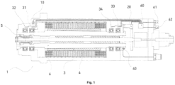
- the figure 1 shows a sectional view of a spindle 1 for a machine tool.
- the spindle comprises a spindle shaft 6 and a clamping interface 5 mounted at the front end of the spindle shaft.
- the shaft is driven by a motor including a rotor 3 and a stator 4.
- the rotor is arranged on the outer surface of the draft and is surrounded by the stator.
- the first bearing and the second bearing are arranged on the front part of the spindle and the third bearing and the fourth bearing are arranged on the rear part of the spindle.
- On each bearing a bearing temperature sensor is mounted to measure the temperature of the corresponding bearing.
- Figure 1 shows the elements which are relevant for the present invention. Thus, not all elements of the spindle are depicted.
- the arrangements of the sensors and the spindle diagnosis module can be applied also into the spindle having different construction than the spindle shown in figure 1 .
- a vibration sensing unit and a crash sensing unit are integrated in one vibration-crash sensing unit housing 10 and fixedly mounted on a flange of the spindle in a rigid manner.
- the sensor housing has a cube shape and a small dimension of 21x15x18.3mm. Since the space inside the spindle is limited, the small size of the sensing unit can ease the integration of the sensor at an optimum position with a defined orientation in accordance with the axes of the spindle.
- a tool-position monitoring unit 20 is arranged in the rear part of the spindle.
- a motor temperature sensor 30 for measuring the temperature of the motor is arranged on the stator 4.
- a first bearing temperature sensor 31 and a second bearing temperature sensor 32 are arranged on the front part of the spindle, in particular on the first front bearing and the second front bearing of the spindle.
- a third bearing temperature sensor 33 and a fourth bearing temperature sensor 34 are arranged in the back part of the spindle, in particular on the third rear bearing and the fourth rear bearing of the spindle.
- a spindle diagnostic module 60 is arranged in the back part of the spindle and embedded totally inside of the spindle housing.
- a power supply connector 62 for supplying the power for the spindle diagnosis module the sensing units and a communication interface connector 61 are mounted at the end of the spindle.
- Figure 2 shows the communication connections inside the spindle and the communication connections between the spindle and a machine tool 100.
- Figure 2 shows one example of how the spindle communicates with the control unit 102 of the machine tool.
- the vibration sensing unit and the crash sensing unit are configured to communicate with the spindle diagnostic module through a SPI communication interface.
- the tool-position monitoring unit (TPM) 20 is configured to communicate with the spindle diagnostic module through an IO link. Additional sensors can be integrated in the spindle as well.
- the temperature sensor signals of the four bearing temperature sensors for sensing the temperature of bearings are fed directly to the spindle diagnostic module.
- a power supply unit 70 is arranged at the outside of the spindle, for example in the machine tool as shown in the figure 2 and supplies the power to the spindle diagnosis module.
- the spindle diagnostic module can transmit all the data received from the sensing units to the control unit through the Profinet.
- the control unit of the machine tool can also transmit the data through the Profinet to the spindle.
- Figure 2 shows one variant in which a communication module 101 is integrated in the machine tool.
- the Profinet is directly connected to the communication module which again is connected to the control unit of the machine tool.
Landscapes
- Engineering & Computer Science (AREA)
- Mechanical Engineering (AREA)
- Testing Of Devices, Machine Parts, Or Other Structures Thereof (AREA)
- Machine Tool Sensing Apparatuses (AREA)
- Constituent Portions Of Griding Lathes, Driving, Sensing And Control (AREA)
- Turning (AREA)
- Micromachines (AREA)
Priority Applications (4)
| Application Number | Priority Date | Filing Date | Title |
|---|---|---|---|
| EP23203203.7A EP4537975A1 (fr) | 2023-10-12 | 2023-10-12 | Broche pour machine-outil |
| US18/910,275 US20250121467A1 (en) | 2023-10-12 | 2024-10-09 | Spindle for a machine tool |
| JP2024178236A JP2025067870A (ja) | 2023-10-12 | 2024-10-10 | 工作機械用スピンドル |
| CN202411405819.6A CN119819956A (zh) | 2023-10-12 | 2024-10-10 | 一种用于机床的主轴 |
Applications Claiming Priority (1)
| Application Number | Priority Date | Filing Date | Title |
|---|---|---|---|
| EP23203203.7A EP4537975A1 (fr) | 2023-10-12 | 2023-10-12 | Broche pour machine-outil |
Publications (1)
| Publication Number | Publication Date |
|---|---|
| EP4537975A1 true EP4537975A1 (fr) | 2025-04-16 |
Family
ID=88412377
Family Applications (1)
| Application Number | Title | Priority Date | Filing Date |
|---|---|---|---|
| EP23203203.7A Pending EP4537975A1 (fr) | 2023-10-12 | 2023-10-12 | Broche pour machine-outil |
Country Status (4)
| Country | Link |
|---|---|
| US (1) | US20250121467A1 (fr) |
| EP (1) | EP4537975A1 (fr) |
| JP (1) | JP2025067870A (fr) |
| CN (1) | CN119819956A (fr) |
Citations (4)
| Publication number | Priority date | Publication date | Assignee | Title |
|---|---|---|---|---|
| US20050160847A1 (en) * | 2003-10-20 | 2005-07-28 | Siemens Aktiengesellschaft | Spindle device with state monitoring, and monitoring method and monitoring system therefore |
| US20090267429A1 (en) | 2005-09-12 | 2009-10-29 | Moeller Bernd | Spindle Having a Data Acquisition Element which can be Read by a Radio |
| US20150352679A1 (en) * | 2013-03-07 | 2015-12-10 | Mitsubishi Heavy Industries, Ltd. | Abnormality diagnosis device for machine tool, and abnormality diagnosis method |
| EP4147819A1 (fr) * | 2021-09-14 | 2023-03-15 | VEM S.p.A. | Broche électrique et dispositif de diagnostic associé |
-
2023
- 2023-10-12 EP EP23203203.7A patent/EP4537975A1/fr active Pending
-
2024
- 2024-10-09 US US18/910,275 patent/US20250121467A1/en active Pending
- 2024-10-10 JP JP2024178236A patent/JP2025067870A/ja active Pending
- 2024-10-10 CN CN202411405819.6A patent/CN119819956A/zh active Pending
Patent Citations (4)
| Publication number | Priority date | Publication date | Assignee | Title |
|---|---|---|---|---|
| US20050160847A1 (en) * | 2003-10-20 | 2005-07-28 | Siemens Aktiengesellschaft | Spindle device with state monitoring, and monitoring method and monitoring system therefore |
| US20090267429A1 (en) | 2005-09-12 | 2009-10-29 | Moeller Bernd | Spindle Having a Data Acquisition Element which can be Read by a Radio |
| US20150352679A1 (en) * | 2013-03-07 | 2015-12-10 | Mitsubishi Heavy Industries, Ltd. | Abnormality diagnosis device for machine tool, and abnormality diagnosis method |
| EP4147819A1 (fr) * | 2021-09-14 | 2023-03-15 | VEM S.p.A. | Broche électrique et dispositif de diagnostic associé |
Non-Patent Citations (1)
| Title |
|---|
| SEMICONDUCTORS FREESCALE: "Sensors Acceleration Sensors", 31 December 2010 (2010-12-31), XP055632819, Retrieved from the Internet <URL:https://www.nxp.com/docs/en/fact-sheet/MMASERIESFS.pdf> [retrieved on 20191016] * |
Also Published As
| Publication number | Publication date |
|---|---|
| US20250121467A1 (en) | 2025-04-17 |
| CN119819956A (zh) | 2025-04-15 |
| JP2025067870A (ja) | 2025-04-24 |
Similar Documents
| Publication | Publication Date | Title |
|---|---|---|
| JP7046059B2 (ja) | 切れ刃の撓みの推定 | |
| CN109520452B (zh) | 位置测量装置和用于运行位置测量装置的方法 | |
| CN110614539A (zh) | 一种数控机床主轴状态在线实时监测分析方法 | |
| WO2019230520A1 (fr) | Système de diagnostic d'anomalies et capteur de vibrations | |
| KR20220071540A (ko) | 공작기계의 공구 상태 판정 장치 | |
| Suprock et al. | A low cost wireless tool tip vibration sensor for milling | |
| EP4537975A1 (fr) | Broche pour machine-outil | |
| Suprock et al. | A low cost wireless high bandwidth transmitter for sensor-integrated metal cutting tools and process monitoring | |
| JP2001205545A (ja) | 工具交換時期判定システム | |
| CN108138840B (zh) | 用于轴承和轴承装置的传感器组件 | |
| KR101670837B1 (ko) | 가상 주파수 응답함수 기반의 회전기계 이상진단방법과 이를 이용한 회전기계 이상진단장치 | |
| JP2009508093A (ja) | センサ装置 | |
| KR102225195B1 (ko) | 공구부하값 산출 방법 및 이를 이용한 회전체 이상 진단 방법 | |
| US20100115157A1 (en) | Modular data collection module with standard communication interface | |
| González et al. | MEMS accelerometer-based system for inexpensive online CNC milling process chatter detection | |
| CN110411730A (zh) | 一种旋转设备故障判断方法、系统和可读存储介质 | |
| KR20200082743A (ko) | 첨도값 산출 방법 및 이를 이용한 회전체 이상 진단 방법 | |
| Suprock et al. | Predicting endmill tool chatter with a wireless tool tip vibration sensor | |
| US20240075585A1 (en) | Monitoring system for a movable component connected to a stationary component | |
| Ripon et al. | Development a Sensor System for Sensing Rotating Machines Fault of Heavy Industries | |
| Kato et al. | Development of wireless cutting vibration monitoring device fixed to tool holder | |
| Krupp et al. | A Cognitive Sensor System Architecture for the Monitoring of Flexible Machining Systems | |
| CA3035279C (fr) | Estimation de deviation d'un bord de coupe | |
| KR20050063442A (ko) | 유도 전동기 편심 상태 진단장치 | |
| TW201437614A (zh) | 微機電動態檢測裝置 |
Legal Events
| Date | Code | Title | Description |
|---|---|---|---|
| PUAI | Public reference made under article 153(3) epc to a published international application that has entered the european phase |
Free format text: ORIGINAL CODE: 0009012 |
|
| STAA | Information on the status of an ep patent application or granted ep patent |
Free format text: STATUS: THE APPLICATION HAS BEEN PUBLISHED |
|
| AK | Designated contracting states |
Kind code of ref document: A1 Designated state(s): AL AT BE BG CH CY CZ DE DK EE ES FI FR GB GR HR HU IE IS IT LI LT LU LV MC ME MK MT NL NO PL PT RO RS SE SI SK SM TR |
|
| STAA | Information on the status of an ep patent application or granted ep patent |
Free format text: STATUS: REQUEST FOR EXAMINATION WAS MADE |
|
| 17P | Request for examination filed |
Effective date: 20251013 |
|
| RAP3 | Party data changed (applicant data changed or rights of an application transferred) |
Owner name: UNITED MACHINING MILL AG |
|
| GRAP | Despatch of communication of intention to grant a patent |
Free format text: ORIGINAL CODE: EPIDOSNIGR1 |
|
| STAA | Information on the status of an ep patent application or granted ep patent |
Free format text: STATUS: GRANT OF PATENT IS INTENDED |