EP4538123A1 - Boîte à chocs pour un ensemble pare-chocs d'un véhicule automobile ainsi qu'ensemble pare-chocs d'un véhicule automobile doté de deux telles boîtes à chocs et procédé de fabrication d'un tel ensemble pare-chocs - Google Patents
Boîte à chocs pour un ensemble pare-chocs d'un véhicule automobile ainsi qu'ensemble pare-chocs d'un véhicule automobile doté de deux telles boîtes à chocs et procédé de fabrication d'un tel ensemble pare-chocs Download PDFInfo
- Publication number
- EP4538123A1 EP4538123A1 EP23202380.4A EP23202380A EP4538123A1 EP 4538123 A1 EP4538123 A1 EP 4538123A1 EP 23202380 A EP23202380 A EP 23202380A EP 4538123 A1 EP4538123 A1 EP 4538123A1
- Authority
- EP
- European Patent Office
- Prior art keywords
- hollow chamber
- chamber component
- legs
- base
- shells
- Prior art date
- Legal status (The legal status is an assumption and is not a legal conclusion. Google has not performed a legal analysis and makes no representation as to the accuracy of the status listed.)
- Pending
Links
Images

Classifications
-
- B—PERFORMING OPERATIONS; TRANSPORTING
- B60—VEHICLES IN GENERAL
- B60R—VEHICLES, VEHICLE FITTINGS, OR VEHICLE PARTS, NOT OTHERWISE PROVIDED FOR
- B60R19/00—Wheel guards; Radiator guards, e.g. grilles; Obstruction removers; Fittings damping bouncing force in collisions
- B60R19/02—Bumpers, i.e. impact receiving or absorbing members for protecting vehicles or fending off blows from other vehicles or objects
- B60R19/24—Arrangements for mounting bumpers on vehicles
- B60R19/26—Arrangements for mounting bumpers on vehicles comprising yieldable mounting means
- B60R19/34—Arrangements for mounting bumpers on vehicles comprising yieldable mounting means destroyed upon impact, e.g. one-shot type
-
- B—PERFORMING OPERATIONS; TRANSPORTING
- B62—LAND VEHICLES FOR TRAVELLING OTHERWISE THAN ON RAILS
- B62D—MOTOR VEHICLES; TRAILERS
- B62D21/00—Understructures, i.e. chassis frame on which a vehicle body may be mounted
- B62D21/15—Understructures, i.e. chassis frame on which a vehicle body may be mounted having impact absorbing means, e.g. a frame designed to permanently or temporarily change shape or dimension upon impact with another body
- B62D21/152—Front or rear frames
-
- B—PERFORMING OPERATIONS; TRANSPORTING
- B62—LAND VEHICLES FOR TRAVELLING OTHERWISE THAN ON RAILS
- B62D—MOTOR VEHICLES; TRAILERS
- B62D25/00—Superstructure or monocoque structure sub-units; Parts or details thereof not otherwise provided for
- B62D25/08—Front or rear portions
Definitions
- a double-shell crash box consisting of two sheet metal shells joined together, which are locally chamfered on the flange plate sides, while the DE 10 2005 029 726 B4 shows a double-shell crash box made of metal sheets, with a bevel in one corner area that increases in size from one end to the other of the crash box.
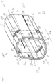
- the hollow chamber component according to the invention for installation in the longitudinal direction of a motor vehicle has two C-shaped shells, each formed from two legs that are connected to one another via a base, and the two C-shaped shells are joined to one another at their legs.
- the hollow chamber component according to the invention is characterized in that the shells consist of cold-formed steel and are each formed with at least one chamfer in their connection areas to the respective base, said at least one chamfer being opposite the legs and/or the legs connecting base is inclined by an angle ⁇ between 120° and 160° and is formed with at least one bead at an end length section.
- crash boxes are intended to collapse in a targeted manner in the event of a crash and, during deformation, absorb as much crash energy as possible and convert it into deformation energy.
- the beads are arranged transversely to the longitudinal direction of the crash box. Such beads form Then, corresponding predetermined bending or deformation points are created, which initiate a targeted collapse of the crash box in the event of a crash, thus enabling targeted deformation of the crash box, with as much crash energy as possible being absorbed by the deformation of the crash box. Excess crash energy is then redirected into the longitudinal member and around the passenger compartment, so that it suffers no or only minimal damage, thus increasing the safety of the occupants in the passenger compartment.
- the two C-shaped shells 2 and 3 are joined together via their legs 4 and 5, as well as their legs 6 and 7.
- the legs 4 and 5 of the upper shell 2 are butt-joined to the legs 6 and 7 of the lower shell 3 via joining surfaces 28.
- the joining surfaces 28 are joined by welding across several joining points 29.
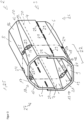
- FIG. 2 A second exemplary embodiment of a hollow chamber component 1 according to the invention for installation in the longitudinal direction of a motor vehicle is shown in a perspective view, wherein this exemplary embodiment is also designed as a crash box 25.
- the crash box 25 is also formed from two C-shaped half-shells 2 and 3.
- the upper shell 2 also consists of two legs 4 and 5, which are connected to a base 8 in connecting regions 10 and 11 via chamfers 14 and 16 or 15 and 17. This means that there are two chamfers per shell, each arranged in pairs, which connect one leg to the base, while in Figure 1 only a single bevel connects the base with each leg.
- the embodiment of the Figure 2 has flat surfaces with a rectangular base area for the bases 8 and 9, the legs 4, 5, 6 and 7 as well as the chamfers 14, 15, 16, 17, 18, 19, 20 and 21.
Landscapes
- Engineering & Computer Science (AREA)
- Mechanical Engineering (AREA)
- Chemical & Material Sciences (AREA)
- Combustion & Propulsion (AREA)
- Transportation (AREA)
- Body Structure For Vehicles (AREA)
Priority Applications (1)
| Application Number | Priority Date | Filing Date | Title |
|---|---|---|---|
| EP23202380.4A EP4538123A1 (fr) | 2023-10-09 | 2023-10-09 | Boîte à chocs pour un ensemble pare-chocs d'un véhicule automobile ainsi qu'ensemble pare-chocs d'un véhicule automobile doté de deux telles boîtes à chocs et procédé de fabrication d'un tel ensemble pare-chocs |
Applications Claiming Priority (1)
| Application Number | Priority Date | Filing Date | Title |
|---|---|---|---|
| EP23202380.4A EP4538123A1 (fr) | 2023-10-09 | 2023-10-09 | Boîte à chocs pour un ensemble pare-chocs d'un véhicule automobile ainsi qu'ensemble pare-chocs d'un véhicule automobile doté de deux telles boîtes à chocs et procédé de fabrication d'un tel ensemble pare-chocs |
Publications (1)
| Publication Number | Publication Date |
|---|---|
| EP4538123A1 true EP4538123A1 (fr) | 2025-04-16 |
Family
ID=88297159
Family Applications (1)
| Application Number | Title | Priority Date | Filing Date |
|---|---|---|---|
| EP23202380.4A Pending EP4538123A1 (fr) | 2023-10-09 | 2023-10-09 | Boîte à chocs pour un ensemble pare-chocs d'un véhicule automobile ainsi qu'ensemble pare-chocs d'un véhicule automobile doté de deux telles boîtes à chocs et procédé de fabrication d'un tel ensemble pare-chocs |
Country Status (1)
| Country | Link |
|---|---|
| EP (1) | EP4538123A1 (fr) |
Citations (11)
| Publication number | Priority date | Publication date | Assignee | Title |
|---|---|---|---|---|
| JPH02175452A (ja) | 1988-12-28 | 1990-07-06 | Isuzu Motors Ltd | 車両の衝撃吸収装置 |
| SE529105C2 (sv) * | 2005-09-23 | 2007-05-02 | Gestamp Hardtech Ab | Krockbox och sätt att fästa en stötfångarbalk |
| DE102005029726B4 (de) | 2005-06-24 | 2007-08-02 | Benteler Automobiltechnik Gmbh | Stoßfänger für ein Kraftfahrzeug |
| WO2007086787A1 (fr) * | 2006-01-24 | 2007-08-02 | Gestamp Hardtech Ab | Boite de vitesses non synchronisee pour vehicule |
| DE102006013274A1 (de) | 2006-03-21 | 2007-09-27 | Benteler Automobiltechnik Gmbh | Stoßfängeranordnung |
| WO2014083926A1 (fr) * | 2012-11-30 | 2014-06-05 | アイシン精機株式会社 | Boîte d'écrasement |
| EP2979932A1 (fr) * | 2013-03-28 | 2016-02-03 | Aisin Seiki Kabushiki Kaisha | Structure de liaison de pare-chocs et boîte d'écrasement |
| US20170021868A1 (en) * | 2015-07-22 | 2017-01-26 | Toyota Jidosha Kabushiki Kaisha | Vehicle front section structure |
| EP3173293A1 (fr) * | 2015-11-27 | 2017-05-31 | Ford Global Technologies, LLC | Élément structurel |
| US20180281715A1 (en) * | 2017-04-03 | 2018-10-04 | City University Of Hong Kong | Energy absorbing device |
| US20220348263A1 (en) | 2019-06-28 | 2022-11-03 | Nippon Steel Corporation | Shock absorbing member, method for producing shock absorbing member, and method for producing steel sheet for cold plastic working |
-
2023
- 2023-10-09 EP EP23202380.4A patent/EP4538123A1/fr active Pending
Patent Citations (11)
| Publication number | Priority date | Publication date | Assignee | Title |
|---|---|---|---|---|
| JPH02175452A (ja) | 1988-12-28 | 1990-07-06 | Isuzu Motors Ltd | 車両の衝撃吸収装置 |
| DE102005029726B4 (de) | 2005-06-24 | 2007-08-02 | Benteler Automobiltechnik Gmbh | Stoßfänger für ein Kraftfahrzeug |
| SE529105C2 (sv) * | 2005-09-23 | 2007-05-02 | Gestamp Hardtech Ab | Krockbox och sätt att fästa en stötfångarbalk |
| WO2007086787A1 (fr) * | 2006-01-24 | 2007-08-02 | Gestamp Hardtech Ab | Boite de vitesses non synchronisee pour vehicule |
| DE102006013274A1 (de) | 2006-03-21 | 2007-09-27 | Benteler Automobiltechnik Gmbh | Stoßfängeranordnung |
| WO2014083926A1 (fr) * | 2012-11-30 | 2014-06-05 | アイシン精機株式会社 | Boîte d'écrasement |
| EP2979932A1 (fr) * | 2013-03-28 | 2016-02-03 | Aisin Seiki Kabushiki Kaisha | Structure de liaison de pare-chocs et boîte d'écrasement |
| US20170021868A1 (en) * | 2015-07-22 | 2017-01-26 | Toyota Jidosha Kabushiki Kaisha | Vehicle front section structure |
| EP3173293A1 (fr) * | 2015-11-27 | 2017-05-31 | Ford Global Technologies, LLC | Élément structurel |
| US20180281715A1 (en) * | 2017-04-03 | 2018-10-04 | City University Of Hong Kong | Energy absorbing device |
| US20220348263A1 (en) | 2019-06-28 | 2022-11-03 | Nippon Steel Corporation | Shock absorbing member, method for producing shock absorbing member, and method for producing steel sheet for cold plastic working |
Similar Documents
| Publication | Publication Date | Title |
|---|---|---|
| EP0425059B1 (fr) | Profilé en acier de forme tubulaire pour renforcer les portes de véhicules | |
| EP2371974B1 (fr) | Procédé de traitement thermique partiel d'un composant de véhicule automobile et composant de carrosserie | |
| EP0814998B1 (fr) | Systeme de bras de suspension | |
| DE102013108265B4 (de) | Baugruppe von gehärteten Bauteilen und Verfahren zur Herstellung | |
| DE202017100049U1 (de) | Zwölfeckiges Verstärkungselement für ein Fahrzeug mit geraden und gebogenen Seiten und optimiertem Verhältnis von Länge der geraden Seite zu Radius der gebogenen Seite | |
| DE102011120519A1 (de) | Verstärkung für eine Fahrzeugsäule, insbesodnere die B-Säule eines Fahrzeuges | |
| EP1970260A2 (fr) | Crashbox et agencement de pare-chocs de véhicule automobile | |
| DE102013015420B4 (de) | Stoßfängersystem und Verfahren für die Herstellung eines Stoßfängersystems | |
| DE102010012832A1 (de) | Kraftfahrzeugsäule | |
| DE102014115887A1 (de) | Crashbox für ein Stoßfängersystem eines Kraftfahrzeugs | |
| DE102011052153A1 (de) | Verfahren zur Herstellung eines Kraftfahrzeug-Biegeträgers und Kraftfahrzeug-Biegeträger | |
| DE102013015421A1 (de) | Stoßfängersystem und Verfahren für die Herstellung eines Stoßfängersystems | |
| EP1597135B1 (fr) | Carrosserie avant ou arriere d'un vehicule et sa prise de masse | |
| DE102015100261B4 (de) | Träger für ein Kraftfahrzeug und Herstellungsverfahren für einen Träger für ein Kraftfahrzeug | |
| EP4359286B1 (fr) | Procédé d'assemblage d'une carrosserie de véhicule automobile | |
| DE10333678A1 (de) | Verfahren zum Herstellen eines abschnittweise verstärkten rohrförmigen Trägers aus Metall, insbesondere für Tragstrukturen in Kraftfahrzeugen | |
| EP1636083A1 (fr) | Support pour carrosserie de vehicule | |
| DE4436882C2 (de) | Blechbauteil mit lastaufnehmender Funktion | |
| EP4538123A1 (fr) | Boîte à chocs pour un ensemble pare-chocs d'un véhicule automobile ainsi qu'ensemble pare-chocs d'un véhicule automobile doté de deux telles boîtes à chocs et procédé de fabrication d'un tel ensemble pare-chocs | |
| DE102010012831A1 (de) | Getriebetunnel | |
| DE102019124020B4 (de) | Stoßfängerquerträger für ein Kraftfahrzeug | |
| DE102013012583A1 (de) | Verfahren zur Herstellung eines Energieaufnahmeelements und Energieaufnahmeelement | |
| DE102018109992A1 (de) | Kraftfahrzeug-Stoßfängeranordnung und Verfahren zur Herstellung | |
| DE102024112666B4 (de) | Verfahren zur Herstellung einer Fahrwerkskomponente, Fahrwerkskomponente und Verwendung eines Halbzeugs zur Herstellung einer Fahrwerkskomponente | |
| DE102020109579A1 (de) | Träger für ein Kraftfahrzeug und Verfahren zur Herstellung eines Trägers |
Legal Events
| Date | Code | Title | Description |
|---|---|---|---|
| PUAI | Public reference made under article 153(3) epc to a published international application that has entered the european phase |
Free format text: ORIGINAL CODE: 0009012 |
|
| STAA | Information on the status of an ep patent application or granted ep patent |
Free format text: STATUS: THE APPLICATION HAS BEEN PUBLISHED |
|
| AK | Designated contracting states |
Kind code of ref document: A1 Designated state(s): AL AT BE BG CH CY CZ DE DK EE ES FI FR GB GR HR HU IE IS IT LI LT LU LV MC ME MK MT NL NO PL PT RO RS SE SI SK SM TR |
|
| STAA | Information on the status of an ep patent application or granted ep patent |
Free format text: STATUS: REQUEST FOR EXAMINATION WAS MADE |
|
| 17P | Request for examination filed |
Effective date: 20250909 |