EP4538193A1 - Texturierte oberfläche für getränkebehälter - Google Patents
Texturierte oberfläche für getränkebehälter Download PDFInfo
- Publication number
- EP4538193A1 EP4538193A1 EP23461666.2A EP23461666A EP4538193A1 EP 4538193 A1 EP4538193 A1 EP 4538193A1 EP 23461666 A EP23461666 A EP 23461666A EP 4538193 A1 EP4538193 A1 EP 4538193A1
- Authority
- EP
- European Patent Office
- Prior art keywords
- ink
- varnish
- protrusions
- beverage container
- applying
- Prior art date
- Legal status (The legal status is an assumption and is not a legal conclusion. Google has not performed a legal analysis and makes no representation as to the accuracy of the status listed.)
- Pending
Links
Images


Classifications
-
- B—PERFORMING OPERATIONS; TRANSPORTING
- B65—CONVEYING; PACKING; STORING; HANDLING THIN OR FILAMENTARY MATERIAL
- B65D—CONTAINERS FOR STORAGE OR TRANSPORT OF ARTICLES OR MATERIALS, e.g. BAGS, BARRELS, BOTTLES, BOXES, CANS, CARTONS, CRATES, DRUMS, JARS, TANKS, HOPPERS, FORWARDING CONTAINERS; ACCESSORIES, CLOSURES, OR FITTINGS THEREFOR; PACKAGING ELEMENTS; PACKAGES
- B65D65/00—Wrappers or flexible covers; Packaging materials of special type or form
- B65D65/38—Packaging materials of special type or form
- B65D65/42—Applications of coated or impregnated materials
-
- B—PERFORMING OPERATIONS; TRANSPORTING
- B65—CONVEYING; PACKING; STORING; HANDLING THIN OR FILAMENTARY MATERIAL
- B65D—CONTAINERS FOR STORAGE OR TRANSPORT OF ARTICLES OR MATERIALS, e.g. BAGS, BARRELS, BOTTLES, BOXES, CANS, CARTONS, CRATES, DRUMS, JARS, TANKS, HOPPERS, FORWARDING CONTAINERS; ACCESSORIES, CLOSURES, OR FITTINGS THEREFOR; PACKAGING ELEMENTS; PACKAGES
- B65D23/00—Details of bottles or jars not otherwise provided for
- B65D23/08—Coverings or external coatings
- B65D23/0807—Coatings
- B65D23/0814—Coatings characterised by the composition of the material
- B65D23/0828—Coatings characterised by the composition of the material consisting mainly of paints or lacquers
-
- B—PERFORMING OPERATIONS; TRANSPORTING
- B41—PRINTING; LINING MACHINES; TYPEWRITERS; STAMPS
- B41F—PRINTING MACHINES OR PRESSES
- B41F23/00—Devices for treating the surfaces of sheets, webs, or other articles in connection with printing
- B41F23/005—Devices for treating the surfaces of sheets, webs, or other articles in connection with printing of non-flat articles
-
- B—PERFORMING OPERATIONS; TRANSPORTING
- B44—DECORATIVE ARTS
- B44C—PRODUCING DECORATIVE EFFECTS; MOSAICS; TARSIA WORK; PAPERHANGING
- B44C1/00—Processes, not specifically provided for elsewhere, for producing decorative surface effects
- B44C1/20—Applying plastic materials and superficially modelling the surface of these materials
- B44C1/205—Applying plastic materials and superficially modelling the surface of these materials chemical modelling
-
- B—PERFORMING OPERATIONS; TRANSPORTING
- B65—CONVEYING; PACKING; STORING; HANDLING THIN OR FILAMENTARY MATERIAL
- B65D—CONTAINERS FOR STORAGE OR TRANSPORT OF ARTICLES OR MATERIALS, e.g. BAGS, BARRELS, BOTTLES, BOXES, CANS, CARTONS, CRATES, DRUMS, JARS, TANKS, HOPPERS, FORWARDING CONTAINERS; ACCESSORIES, CLOSURES, OR FITTINGS THEREFOR; PACKAGING ELEMENTS; PACKAGES
- B65D17/00—Rigid or semi-rigid containers specially constructed to be opened by cutting or piercing, or by tearing of frangible members or portions
-
- B—PERFORMING OPERATIONS; TRANSPORTING
- B65—CONVEYING; PACKING; STORING; HANDLING THIN OR FILAMENTARY MATERIAL
- B65D—CONTAINERS FOR STORAGE OR TRANSPORT OF ARTICLES OR MATERIALS, e.g. BAGS, BARRELS, BOTTLES, BOXES, CANS, CARTONS, CRATES, DRUMS, JARS, TANKS, HOPPERS, FORWARDING CONTAINERS; ACCESSORIES, CLOSURES, OR FITTINGS THEREFOR; PACKAGING ELEMENTS; PACKAGES
- B65D2203/00—Decoration means, markings, information elements, contents indicators
Definitions
- the inks may include discrete regions of varnish antagonistic ink separated by varnish compatible ink.
- a varnish is applied over an ink pattern.
- the varnish migrates to fill areas of the varnish compatible ink to form a regular pattern of protrusions having heights of about 30-35 microns.
- These protrusions provide a small amount of improvement to the grip and grip feel of the container, however such containers may still be slick, especially when wet.
- the use of lithography complicates the manufacturing process. Therefore, improvements in beverage container surfaces and methods for producing such containers are desired.
- Embodiments of the present invention may encompass beverage containers.
- the beverage containers may include a container body having an outer surface.
- the beverage containers may include a textured graphic disposed on a portion of the outer surface.
- the textured graphic may include a plurality of protrusions that are randomly oriented on the portion of the outer surface. At least some of the plurality of protrusions may have a lateral dimension that is at least 1 mm. At least some of the plurality of protrusions may have a maximum height of between 40 microns and 80 microns relative to a lowest point on the portion of the outer surface.
- Each of the plurality of protrusions may include an ink and a varnish.
- the ink may exhibit a surface tension of less than about 30 mN/m 2 when dry.
- An upper surface of at least some of the plurality of protrusions may include at least one popped air bubble. At least some of the plurality of protrusions may have a lateral dimension that is at least 2 mm. Substantially all of the plurality of protrusions may include irregular shapes.
- the container body may include a neck. The portion of the outer surface may be disposed below the neck. The portion of the outer surface may extend entirely about a circumference of the outer surface.
- Some embodiments of the present technology may encompass methods of applying a texture to a beverage container.
- the methods may include applying an ink to at least a portion of an outer surface of a beverage container.
- the methods may include applying a varnish over the ink, which may be wet in some embodiments.
- the methods may include applying heat to the varnish and the ink to initiate a reaction between the ink and the varnish that causes accumulation of the varnish to form a textured graphic on the outer surface.
- the textured graphic may include a plurality of protrusions. At least some of the plurality of protrusions may have a lateral dimension that is at least 1 mm. At least some of the plurality of protrusions may have a maximum height of between 40 microns and 80 microns relative to a lowest point on the portion of the outer surface.
- the reaction may be caused by a difference in surface tension between the wet ink and the varnish.
- the difference in surface tension between the wet ink and the varnish may be at least 20 mN/m 2 .
- the plurality of protrusions may be arranged to fill in voids present in the repeating pattern.
- the ink may include a varnish antagonistic ink.
- the voids may include a varnish compatible ink.
- Applying heat to the varnish and the wet ink may cause air bubbles to form and pop to form dimples in an upper surface of at least some of the plurality of protrusions.
- Applying heat to the varnish and the wet ink may include exposing the beverage container to a temperature of between 175 °C and 230 °C for between 10 seconds and 60 seconds.
- the methods may include fully curing the ink and the varnish.
- Some embodiments of the present invention may include systems for applying texture to a beverage container.
- the systems may include a printing device that is configured to apply an ink to at least a portion of an outer surface of a beverage container.
- the systems may include a coating device that is configured to apply a varnish over the wet ink.
- the systems may include a heating device that is configured to apply heat to the varnish and the wet ink to initiate a reaction between the wet ink and the varnish that causes accumulation of the varnish to form a textured graphic on the outer surface.
- the textured graphic may include a plurality of protrusions. At least some of the plurality of protrusions may have a lateral dimension that is at least 1 mm. At least some of the plurality of protrusions may have a maximum height of between 40 microns and 80 microns relative to a lowest point on the portion of the outer surface.
- the heating device may be configured to expose the beverage container to a temperature of between 175 °C and 230 °C for between 10 seconds and 60 seconds.
- the systems may be configured to apply texture to at least 800 cans per minute.
- the heating device may include a pin oven.
- Embodiments of the present invention are directed to systems and methods for manufacturing product containers (e.g., food and/or beverage cans, bottles, and the like) that include textured surfaces that improve the ease of securely gripping of the containers.
- the containers described herein may include textures formed by protrusions that have larger footprints and greater heights than textures used on conventional product packages.
- substantially all of the protrusions may have at least one lateral dimension that is greater than 1 mm and maximum heights of between 40 microns and 60 microns.
- some of the protrusions may include dimples or other features (which may or may not have relatively pointed edges) formed along an upper surface of the protrusions. Such dimples may be formed, for example, by carefully controlling a drying time and/or temperature, air bubbles may form that subsequently burst to form the dimples or other features.
- the textured graphics in accordance with the present invention may be produced by applying varnish antagonistic ink (and possibly varnish compatible ink) to a surface of the container.
- the ink may be wet or partially cured, and a varnish may be applied atop the ink.
- the varnish and the ink may have different surface tensions.
- the varnish and ink may be exposed to heat, which may cause the varnish to agglomerate in random patterns, forming protrusions across the outer surface of the container.
- the textured graphics described herein may be produced without the use of lithography, which may simplify the manufacturing process. However, the use of lithography to apply one or more inks in patterns (which may be repeating patterns in some embodiments) may be utilized to further enhance the texture.
- beverage cans While described primarily in the context of beverage cans, it will be appreciated that the systems and methods described herein may be utilized in other container manufacturing processes, especially those in which a texture needs to be applied to a relatively smooth surface. Additionally, the techniques described herein are not limited to aluminum beverage cans and may be utilized in other applications (such as other canning operations, bottling operations, and/or other operations in which a specific package is filled with a particular object and/or substance) and/or with other materials, such as other metals, glass, and/or plastic materials.
- FIG. 1 illustrates a schematic view of a production line 100 for producing beverage cans, such as aluminum cans.
- Production line 100 will be described as including a number of different devices and is merely representative of one example of a production line. It will be appreciated that numerous variations may exist and that functionality described in relation to one or more devices may be combined and performed by a single device in some embodiments, while in other embodiments functionality attributed to a single device may be performed by a number of distinct devices. Additionally, some embodiments may include additional steps and/or omit one or more steps.
- Production line 100 may include an uncoiler 102 that lubricates sheet metal and feeds the lubricated sheet metal into a cupping press 104.
- the cupping press 104 may include a punch that punches out disc-shaped blanks from the sheet metal and subsequently forms the blanks into cup-shapes.
- the flat disc-shaped blanks may be positioned between a drawing die and a blank holder.
- the drawing die may define a receptacle that is sized to be larger than a final diameter of the finished can.
- a punch may press a portion of the blank into the receptacle such that the blank is transformed into a cup-shape.
- the cup-shaped blank may be transported to a bodymaker 106, which may form a general shape of the can.
- the bodymaker 106 may position each cup-shaped blank over a re-drawing die, which may have a diameter that approximately matches a diameter of the finished can.
- a punch may press the cup-shaped blank through the re-drawing die, which increases the height of the blank while reducing a diameter of the blank to be approximately equal to that of the finished can.
- a number of ironing stages may be performed on each blank. For example, in some embodiments each can blank may be passed through three or more ironing stages.
- the blank may be positioned over an ironing die that defines a central aperture, with each successive ironing stage having an ironing die that has an inner diameter that is slightly smaller than the outer diameter of the can blank.
- a punch may press the can blank through the ironing die, which causes the can blank to be stretched vertically, while keeping an inner diameter of the blank unchanged.
- the ironing process may be repeated any number of times until the can blank has a height that is greater than a final height of the finished can.
- the bodymaker 106 may spray or otherwise supply a lubricating fluid to the can blank to lubricate and cool the can blank during formation of the can body.
- each can blank may be sprayed with two stages of an acid wash.
- the acidic wash may include sulfuric acid (such as 30% to 40% molar H 2 SO 4 ) and/or other acid-based cleaning agents, which may etch and/or otherwise remove a thin layer of material from the surface of the can blank.
- Additional cleaning solutions may include, without limitation, Ridoline 740E, Ridoline 120SNF, Bonderite 404S, and/or Bonderite 77 produced by Henkel of Düsseldorf, Germany.
- a number of water washes may be performed on each can blank after the acid wash stages. For example, deionized water may be sprayed and/or otherwise applied to the can blank to rinse away the other cleaning solutions. After washing, the can blanks may be transported to a dryer 112.
- the dryer 112 may include an oven, air jet, and/or other drying mechanism that may dry the can blanks prior to applying any decoration to the can blank.
- the dried can blanks may be transported to a decorator 114, which may apply a decoration (such as a brand name, product name, nutrition information, etc.) to an outer surface of the can blank.
- the decorator 114 may apply any decoration to the outer surface of the can blank in one or more steps.
- the decorator 114 may be an 8-color offset machine (or other number of colors) that may apply ink to the outer surface of the can blank using a rotation printing process to generate a desired decoration.
- the decorator 114 may apply an overprint varnish to the ink.
- a bottom of the can may be rim-coated, which may help facilitate rotation and/or other movement of the can blank along the production line.
- the decorated can blanks may be cured and/or partially cured within a pin oven 116 to harden the ink and varnish.
- the cured can blanks may be transported to a lacquer applicator 118.
- the lacquer applicator 118 may apply a food-grade lacquer to an interior surface of each can blank. This lacquer may help ensure that the final beverage and metal do not contact and/or react with one another. For example, the lacquer may prevent a beverage from eating through the metal, and may also prevent materials from the metal from leeching into and/or reacting with the beverage.
- the lacquer may be dried within a curing oven 120, which may be a pin oven in some embodiments.
- the can blanks may then be transported to a necker 122.
- the necker 122 may shape a top end of the can blank to form a neck.
- a number of necking stages may gradually narrow the top end of the can blank to form the neck.
- Each necking stage may include an inner die that is inserted within the can blank and a necking die that is positioned outside the can blank. In each stage, the necking die has a slightly smaller inner diameter so as to slightly bend the top of the can inward to form the neck. In some instances, as many as 11 necking stages may be used to form the neck.
- a top edge of the neck may be curved over to form a flange that may later be used in sealing the can.
- the cans may be transported to a palletizer 124, which may arrange the cans on pallets for transport to a filling facility and/or station 126.
- the filling station 126 may be in a same facility as the rest of the production line 100 and/or may be located in a remote facility. For example, a manufacturer of the cans may provide the palletized cans to a bottler, which may fill and seal the cans for shipment to customers. At the filling station 126, each can may be filled with a beverage (or other substance) that corresponds to the decoration and/or other identifier (such as a barcode) that is printed on the can. After the cans are filled, a top, such as a lid having a stay-on tab, may be affixed to the flanged neck of the can.
- a beverage or other substance
- identifier such as a barcode
- edges of the lid and flanged neck may be crimped together, oftentimes with a sealant disposed therebetween to help seal the can.
- the liquid Prior to and/or during filling, the liquid may be pasteurized to kill bacteria within the can. This process may involve heating the liquid up to a temperature of at least 63 °C in some embodiments.
- the pasteurization may include heating the liquid prior to dispensing the liquid into the cans.
- the cans may be heated within a pasteurization oven to heat the liquid inside the cans to the necessary temperature.
- heated water such as water at 65 °C - 95 °C
- heated water may be sprayed on the filled cans, at least partially submerged in heated water, and/or placed in an over to heat the contents of the can.
- the cans may be cooled prior to palletization, such as by spraying the cans with cool water. This cooling may help prevent the formation of condensation on the outside of the cans, which may damage cardboard used in the palletization/packing process.
- Transportation of the cans/blanks between the various devices may be performed by different conveyor mechanisms 128 throughout the manufacturing process.
- the mechanism chosen for a given stage may depend on a number of lines of cans entering and/or exiting a given device, a desired throughput, a desired orientation of the cans entering and/or exiting a given device, a current state of the cans entering and/or exiting a given device, and/or other factors.
- Possible conveyor mechanisms may include conveyor belts, vacuum conveyors (such as vacuum bridges), chain conveyors, roller conveyors, chute conveyors, vertical conveyors, wheel conveyors, pneumatic conveyors, and/or other conveyor mechanisms.
- the production line 100 may include any number of quality control stations (not shown) positioned at one or more locations along the production line 100.
- the quality control stations may check for defects within the cans and ensure that each can meets a required quality control standard.
- the quality control stations may include one or more sensors (such as imaging sensors, scales, coating thickness gauges, enamel raters, tension meters, and the like) that may be used to determine whether individual cans meet the quality control standards.
- the sensors may detect a wall thickness of the cans, a dome depth, can weight, proper diameters of the cans, a can height, presence of varnish and/or lacquer, quality of decoration (possibly including a barcode and/or other identifier), presence of a bottom rim coating, packaging quality, and the like.
- Production line 100 may include one or more removal mechanisms (not shown) that may be positioned at one or more points along the production line 100.
- the removal mechanisms may be used to remove defective and/or otherwise imperfect cans from the production line 100. For example, if one of the quality control stations determines that a given can or group of cans does not meet a predetermined quality control standard, a removal mechanism may remove the can or group of cans from the production line 100. In some instances, only those cans that have been determined to not meet quality control standard may be removed, while in other embodiments a section of cans proximate the defective can or cans may also be removed. The removal of cans proximate a defective can may be particularly useful in some instances.
- the removal mechanisms may take many forms, such as air guns, vacuum bridges, mechanical arms, magnetic rejection system (for packaging materials that are ferromagnetic), and/or other known removal mechanisms.
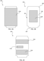
- FIGs. 2A-2G illustrate one example of a container 200 having a textured surface in accordance with the present invention.
- container 200 is an aluminum can, however in other embodiments container 200 may be a glass bottle, plastic bottle, and/or other form of beverage container.
- Container 200 may include a container body 202 having a base 204, a generally cylindrical sidewall 206, and a neck 208.
- a top may be affixed to a top end of neck 208 and may include a tab for opening the top.
- Container 200 may take other forms in various embodiments.
- a portion of the outer surface of container 200 may include one or more textured graphics 210.
- textured graphic 210 may extend about all or a portion of sidewall 206 in some embodiments.
- textured graphic 210a covers substantially all of sidewall 206 (e.g., is not present on neck 208 and/or base 204).
- textured graphic 210b extends partially about a circumference of sidewall 206 and partially about a height of sidewall 206.
- textured graphic 210c includes multiple distinct portions that are spaced apart from one another. The portion of textured graphic 210c may be the same and/or different shape and/or size and may be positioned at similar or different rotational and/or height positions on container 200. While shown with three portions, it will be appreciated that textured graphic 210c may include any number of portions. For example, textured graphic 210c may include one or more portions, two or more portions, three or more portions, four or more portions, five or more portions, ten or more portions, twenty or more portions, 50 or more portions, or greater.
- Textured graphic 210 may cover any percentage of the outer surface of sidewall 206 (and possibly some or all of neck 208 and/or base 204). For example, textured surface 210 may cover between 5% and 90% of the outer surface of sidewall 206, oftentimes between 25% and 90%, and more commonly between 50% and 90% of the outer surface of sidewall 206. Textured graphic 210 and/or each portion thereof may extend along between 5% and 100% of a height of sidewall 206 and/or between 5% and 100% of a circumference of sidewall 206.
- a portion of sidewall 206 may include a textured graphic 210, while other regions of sidewall 206 may include a smooth surface (e.g., no applied texture) and/or areas of less aggressive textures (e.g., textures applied using conventional techniques in which the protrusions have lateral dimensions that do not exceed 1 mm and heights that do not exceed 35 microns).
- areas of sidewall 206 that are likely to be grasped by a user may include one or more textured graphics 210, while other areas of sidewall 206 have no texture or conventional textured graphics.
- textured graphic 210 may form all or a part of a logo, graphic, text, and/or other aesthetic design of container 200.
- textured graphic 210 may be formed from one or more inks (at least some of which may be pigmented) that form all or part of the aesthetic design of container 200 and one or more varnishes that overlay and protect the ink.
- some or all of textured graphic 210 may be formed from clear ink and/or varnish, with textured graphic 210 being overlaid atop a preexisting graphic.
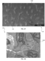
- textured graphic 210 may include a number of protrusions 212 that extend radially outward from the outer surface of container.
- protrusions 212 may arranged in different patterns and/or shapes.
- protrusions 212a may be arranged in repeating patterns of predefined and/or random/irregular shapes about the outer surface.
- the predefined shapes may include circles, rectangles, logos, images, numbers, letters, other polygons, and/or other shapes that are defined using a lithographic mask.
- a pattern of predefined shapes and predefined voids between the shapes may be applied using multiple inks.
- the predefined shapes may be applied using varnish-antagonistic ink and the voids may be applied using varnish-compatible ink.
- varnish applied to the ink may flow away from the varnish-antagonistic ink present in the predefined shapes and collect within the voids to form protrusions 212a having predefined shapes matching shapes of the voids in the lithographic mask.
- the pattern of shapes and voids is regular such that repeating pattern of protrusions 212a is created, with consistent spacing between protrusions 212a.
- protrusions 212b may be randomly oriented with random/irregular shapes about the outer surface.
- protrusions 212 may have at least one lateral dimension that is at least 1 mm, at least 1.1 mm, at least 1.2 mm, at least 1.25 mm, at least 1.5 mm, at least 1.75 mm, at least 2 mm, at least 2.25 mm, at least 2.5 mm, at least 3 mm, or larger, such as up to 5 mm.
- Such protrusions 212 are larger than those in conventional textures, which typically have no lateral dimensions that reach 1 mm.
- Some or all protrusions 212 may have maximum heights (relative to a lowest point on textured graphic 210) of between 40 microns and 80 microns.
- some or all protrusions 212 may have maximum heights of at least 40 microns, at least 45 microns, at least 50 microns, at least 55 microns, at least 60 microns, at least 70 microns, at least 80 microns, at least 100 microns, at least 125 microns, at least 150 microns, or greater.
- Such protrusions 212 are larger than those in conventional textures, which typically have no heights that reach 40 microns. The presence of protrusions 212 having greater lateral dimensions and/or greater maximum heights may provide an enhanced grip relative to conventional textures.
- an upper surface of at least some of protrusions 212 may include at least one popped air bubble 214 as shown in FIGs. 2E-2G .
- Popped air bubbles 214 may be formed, for example, by carefully controlling a drying time and/or temperature during formation of protrusions 212. For example, during formation, air bubbles may form that subsequently burst to form popped air bubbles 214, which may take the form of dimples or other features within upper surfaces of some or all protrusions 212.
- Popped air bubbles 214 may have microscopically small sharp peaks and/or other edges that feel rough to the touch and that may further enhance the gripability of textured graphic 210 and consequently the "textured feel" of the surface of the beverage can.
- Each protrusion 212 may be formed from an agglomeration of varnish atop an ink and may include some amount of ink in some embodiments.
- the inks used to produce textured pattern 210 may include one or more varnish-compatible inks (e.g., inks on which a varnish may be readily adhered and that do not affect the overlaying varnish) and/or one or more varnish-antagonistic inks (e.g., inks that do not readily receive varnish and that may cause an overlaying varnish to agglomerate to some degree).
- the varnish-compatible inks used herein may have surface tensions (when dry) that exceed 35 mN/m 2 , which may enable varnishes to adhere to the ink without being affected.
- varnishes with solids contents over 80% may be used in conjunction with larger volumes of varnish and/or slower ink and/or varnish application speeds may be used to create larger protrusions, such as protrusions having lateral dimensions that are between about 2.5 mm and 5 mm.
- Varnishes may also include between about 0% and 30% by weight of one or more solvents and/or between about 0 ⁇ and 60% by weight of water.
- Suitable varnishes may include, without limitation, Metlac 815675, BPANI/PFASNI 815788, PPG 9319-801, BPANI/PFASNI XG-W7037, and/or Novochem Novoshield 4765.
- FIG. 3 illustrates a system 300 for applying texture to a beverage container.
- System 300 may form part of production line 100 described above and may be used to create textured graphics such as textured graphics 210.
- System 300 may include a decorator 302, which may be similar to decorator 114.
- Decorator 302 may receive can blanks (which may be similar to container 200) that include a container body having a base and cylindrical sidewall.
- Decorator 302 may include at least one printing device 304 and at least one coating device 306.
- Printing device 304 may include an offset printer (e.g., printer using a number of ink-coated blankets or rollers to perform a rotation printing process to generate a desired decoration), an inkjet printer, and/or other printing apparatus.
- Printing device 304 may print or otherwise apply one or more inks to at least a portion of an outer surface of the sidewall to apply a decoration (such as a brand name, product name, nutrition information, etc.) to an outer surface of the can blank.
- Printing device 304 may apply the decoration to the outer surface of the can blank in one or more steps.
- printing device 304 may apply one or more colors of ink to the outer surface of the can blank.
- the colored ink may include varnish-antagonistic ink and/or varnish-compatible ink.
- one or more varnish-antagonistic inks may be applied to the outer surface of uniformly (e.g., as a layer having a substantially consistent thickness) across the portion of the outer surface.
- printing device 304 may apply different inks in a repeating pattern of shapes and voids. The shapes may be applied using varnish-antagonistic ink and the voids may be applied using varnish-compatible ink.
- decorator 302 may optionally include a heating device 308 that is disposed between printing device 304 and coating device 306.
- Heating device 308 may be operable to partially cure the ink prior to and/or as the container is transported to coating device 306.
- heating device 308 may be an oven, convection device and/or other heater that is configured to expose the beverage container to a temperature below the curing temperature of the ink of between 130 °C and 160 °C to partially cure the ink.
- the ink may be partially cured in a passive manner without heating device 308. For example, airflow about the ink may partially cure the ink as the container is transported from printing device 304 to coating device 306.
- Coating device 306 may apply a varnish, such as a clear or matte varnish, preferably antagonistic to the ink, atop the wet or partially cured (e.g., still wet) ink to protect the ink.
- a varnish such as a clear or matte varnish
- the time between a can body being inked to the varnish being applied is in the region of 30-120 milliseconds. During this time the ink will not dry to any significant extent, meaning that the varnish is applied onto the wet ink.
- Coating device 306 may be a spray coater, a roller coater, an anilox coater, a gravure coater, and/or other type of coater.
- System 300 may include a heating device 310 that may be configured to apply heat to the varnish and the ink to initiate a reaction between the ink and the varnish.
- the reaction may cause accumulation of the varnish to form a textured graphic on the outer surface.
- the textured graphic may include a number of protrusions, such as protrusions 212.
- Heating device 310 may include ovens, such as pin ovens (similar to pin oven 116) in some embodiments.
- heating device 310 may be configured to expose the beverage container to a temperature of between 175 °C and 230 °C for between 10 seconds and 60 seconds to initiate the reaction and to harden the ink and varnish.
- the cured can blanks may be transported to a lacquer applicator (similar to lacquer applicator 118), which may apply a food-grade lacquer to an interior surface of each can blank.
- the lacquer, ink, and varnish may be fully dried and cured within a curing oven, such as curing oven 120.
- the can blanks may then be transported to a necker (such as necker 122) for shaping a top end of the can blank to form a neck.
- the graphic texture is not applied to the neck of the can, as the graphic texture may be damaged during the necking process.
- Components of system 300 may be sized to handle large amounts of cans, often enabling texturing and/or other processing of at least 1200 cans per minute.
- FIG. 4 is a flowchart illustrating a process 400 for applying a texture to a beverage container.
- Process 400 may be formed using production line 100 and/or system 300 described herein and may be used to create textured graphics such as textured graphics 210.
- Process 400 may begin at operation 405 by applying one or more inks to at least a portion of an outer surface of a beverage container, such as container 200.
- the ink may be applied using a printing device, such as printing device 304.
- the portion of the outer surface on which the ink is applied may include all or a portion of a sidewall of container and may include one or more distinct portions or regions of the outer surface.
- the portion of the outer surface on which the ink is applied is limited to the sidewall, with the base and/or neck of the container being devoid of ink, however in some embodiments the ink may be applied to some or all of the neck and/or base.
- the inks may include clear and/or pigmented inks and, in some embodiments may be applied to create an aesthetic design on the outer surface of the container.
- applying the ink may include applying one or more varnish-antagonistic inks to the portion of the outer surface.
- the varnish-antagonistic inks may be applied uniformly (e.g., as a layer having a substantially consistent thickness) across the portion of the outer surface.
- applying the ink may include applying one or more varnish-antagonistic inks and one or more varnish-compatible inks to the portion of the outer surface using lithography techniques. For example, a lithography mask may be used to apply different inks in a repeating pattern of shapes and voids. The predefined shapes may be applied using varnish-antagonistic ink and the voids may be applied using varnish-compatible ink.
- the ink may optionally be partially cured at operation 410.
- Partially curing the ink may be passive in some embodiments, such as by airflow as the container is moved to a varnish-application device.
- partially curing the ink may involve applying heat to the ink using a heating device, such as an oven or other heating device 308. Applying heat may optionally involve exposing the ink to temperatures below the curing temperature of the ink of between 130 °C and 160 °C for a time period of between 0.25 seconds to 5 seconds.
- a varnish may be applied over the ink.
- the varnish and the ink may both still be in a wet state when the varnish is applied.
- the varnish may be applied via a coating device such as coating device 306.
- the varnish may be applied in a uniform manner across the ink.
- the varnish may be applied at a rate of between 6 grams and 15 grams per square meter, with higher rates (possibly with varnishes having higher solids content) being used to generate larger/taller protrusions.
- Such application rates may result in a varnish layer that is between 5 microns and 15 microns thick.
- the varnish may be applied at a rate of between 6 grams and 15 grams per square meter, which may result in protrusions having predefined shapes and with maximum heights of at least 40 microns, at least 45 microns, at least 50 microns, at least 55 microns, at least 60 microns, at least 70 microns, at least 80 microns, at least 100 microns, at least 125 microns, at least 150 microns, or greater.
- heat may be applied to the varnish and the ink.
- the heat may be applied via a heating device, such as heating device 310.
- the application of heat may involve exposing the container to a temperature of between 175 °C and 230 °C for between 10 seconds and 60 seconds, although exposure times exceeding 60 seconds (such as up to 120 seconds 180 seconds, or more) may be used in some embodiments, especially where heating device 310 has a large capacity and/or slow manufacturing speeds are utilized.
- the heat may initiate a reaction between the ink and the varnish that causes accumulation of the varnish to form a textured graphic on the outer surface.
- the reaction may be caused by the use of low surface tension inks and the difference in surface tension between the ink and the varnish.
- the difference in surface tension between the ink and the varnish may be at least 10 mN/m 2 , at least 15 mN/m 2 , at least 20 mN/m 2 , at least 25 mN/m 2 , at least 30 mN/m 2 , or greater.
- the textured graphic may be similar to textured graphic 210 and may include a number of protrusions, such as protrusions 212.
- the reaction may result in formation of protrusions that are randomly oriented about the portion of the outer surface of the container.
- the varnish may agglomerate into random clusters about the varnish-antagonistic ink. Each cluster may have a random shape and/or size, with many or all of the protrusions forming unique irregular shapes.
- the varnish may flow away from the varnish-antagonistic ink present in the predefined shapes and collect within the voids to form protrusions having predefined shapes matching shapes of the voids in the lithographic mask.
- At least 75% of the resulting protrusions may have at least one lateral dimension that is at least 1 mm and/or at least 75% of the resulting protrusions may have maximum heights of between 40 microns and 80 microns.
- the application of the heat to the varnish and the partially cured ink causes air bubbles to form and pop to form dimples in an upper surface of at least some of the protrusions.
- the dimples may have microscopically small sharp peaks and/or other edges that feel rough to the touch and that may further enhance the gripability of textured graphic and the "textured feel" of the surface of the container.
- the ink and varnish may be fully cured.
- heat may be applied in excess of the curing temperature of the ink and varnish (which may be between 188 °C and 230 °C) for a period of at least one minute.
- the heat may be applied at a temperature of at least 188 °C for a period of between 2 minutes and 8 minutes and more commonly between 4 minutes and 6 minutes.
- Process 400 may be performed using equipment that is sufficiently large and operable at high enough speeds to apply textured graphics and/or otherwise process at least 800 cans per minute, at least 1200 cans per minute, oftentimes between about 1200 cans per minute and 2200 cans per minute, with rates of between 1400 cans per minute and 2000 cans per minute, between 1600 cans per minute and 1800 cans per minute, or about 1600 cans per minute being common.
- the curing operation may occur after the inside of the container is sprayed with lacquer (and may also cure the lacquer) and prior to necking the container.
- substantially as used herein when referring to a measurable value such as an amount, a temporal duration, a physical attribute (such as frequency), and the like, also encompasses variations of ⁇ 20% or ⁇ 10%, ⁇ 5%, or +0.1% from the specified value, as such variations are appropriate to in the context of the systems, devices, circuits, methods, and other implementations described herein.
- a list of “at least one of A, B, and C” includes any of the combinations A or B or C or AB or AC or BC and/or ABC (i.e., A and B and C).
- a list of "at least one of A, B, and C” may also include AA, AAB, AAA, BB, etc.
Landscapes
- Engineering & Computer Science (AREA)
- Mechanical Engineering (AREA)
- Details Of Rigid Or Semi-Rigid Containers (AREA)
- Printing Methods (AREA)
Priority Applications (3)
| Application Number | Priority Date | Filing Date | Title |
|---|---|---|---|
| EP23461666.2A EP4538193A1 (de) | 2023-10-12 | 2023-10-12 | Texturierte oberfläche für getränkebehälter |
| PCT/IB2023/060429 WO2025078873A1 (en) | 2023-10-12 | 2023-10-16 | Textured surface for beverage containers |
| US18/490,140 US20250121984A1 (en) | 2023-10-12 | 2023-10-19 | Textured surface for beverage containers |
Applications Claiming Priority (1)
| Application Number | Priority Date | Filing Date | Title |
|---|---|---|---|
| EP23461666.2A EP4538193A1 (de) | 2023-10-12 | 2023-10-12 | Texturierte oberfläche für getränkebehälter |
Publications (1)
| Publication Number | Publication Date |
|---|---|
| EP4538193A1 true EP4538193A1 (de) | 2025-04-16 |
Family
ID=88417010
Family Applications (1)
| Application Number | Title | Priority Date | Filing Date |
|---|---|---|---|
| EP23461666.2A Pending EP4538193A1 (de) | 2023-10-12 | 2023-10-12 | Texturierte oberfläche für getränkebehälter |
Country Status (3)
| Country | Link |
|---|---|
| US (1) | US20250121984A1 (de) |
| EP (1) | EP4538193A1 (de) |
| WO (1) | WO2025078873A1 (de) |
Citations (4)
| Publication number | Priority date | Publication date | Assignee | Title |
|---|---|---|---|---|
| US6550389B1 (en) * | 1999-07-27 | 2003-04-22 | Toyo Seikan Kaisha, Ltd. | Printing method for printing on can barrel |
| US20030152724A1 (en) * | 1997-02-26 | 2003-08-14 | Fort James Corporation | Coated paperboards and paperboard containers having improved tactile and bulk insulation properties |
| CN104029884A (zh) * | 2009-07-01 | 2014-09-10 | 菲利普莫里斯生产公司 | 发烟制品容器和发烟制品容器的制造方法 |
| WO2018104714A1 (en) * | 2016-12-08 | 2018-06-14 | Crown Packaging Technology, Inc. | Forming a texture in a can surface decoration |
Family Cites Families (18)
| Publication number | Priority date | Publication date | Assignee | Title |
|---|---|---|---|---|
| US3524583A (en) * | 1968-10-04 | 1970-08-18 | Arthur C Gregory | Anti-slip band and the like |
| US5970865A (en) * | 1997-02-26 | 1999-10-26 | Mitsubishi Materials Corporation | Apparatus and method for printing multi-color images onto cylindrical body |
| US20030235667A1 (en) * | 2002-06-25 | 2003-12-25 | Darr Richard C. | Multilayered plastic container |
| US8607974B2 (en) * | 2008-12-22 | 2013-12-17 | British America Tobacco (Holdings) Limited | Pack for smoking articles |
| ES1078385Y (es) * | 2009-07-01 | 2013-04-04 | Philip Morris Products Sa | Envase para articulos de consumidor |
| BR102012016393A2 (pt) * | 2012-07-02 | 2015-04-07 | Rexam Beverage Can South America S A | Dispositivo de impressão em latas, processo de impressão em latas, lata impressa e blanqueta |
| US9555616B2 (en) * | 2013-06-11 | 2017-01-31 | Ball Corporation | Variable printing process using soft secondary plates and specialty inks |
| EP3169521B1 (de) * | 2014-07-16 | 2018-04-25 | KBA-MetalPrint GmbH | Vorrichtung zum bedrucken von hohlkörpern |
| US10086602B2 (en) * | 2014-11-10 | 2018-10-02 | Rexam Beverage Can South America | Method and apparatus for printing metallic beverage container bodies |
| PL3028856T3 (pl) * | 2014-12-04 | 2019-10-31 | Ball Beverage Packaging Europe Ltd | Urządzenie drukujące |
| US20160215377A1 (en) * | 2015-01-22 | 2016-07-28 | Rexam Beverage Can Company | Methods for Plasma Treatment on a Can Component, Feedstock & Tooling |
| US10976263B2 (en) * | 2016-07-20 | 2021-04-13 | Ball Corporation | System and method for aligning an inker of a decorator |
| US11034145B2 (en) * | 2016-07-20 | 2021-06-15 | Ball Corporation | System and method for monitoring and adjusting a decorator for containers |
| DE102016213214B4 (de) * | 2016-07-20 | 2020-07-16 | Koenig & Bauer Ag | Vorrichtung zum Bedrucken von Hohlkörpern |
| US10739705B2 (en) * | 2016-08-10 | 2020-08-11 | Ball Corporation | Method and apparatus of decorating a metallic container by digital printing to a transfer blanket |
| WO2018031814A1 (en) * | 2016-08-10 | 2018-02-15 | Ball Corporation | Method and apparatus of decorating a metallic container by digital printing to a transfer blanket |
| US11383509B2 (en) * | 2018-11-09 | 2022-07-12 | Ball Corporation | Metering roller for an ink station assembly of a decorator and a method of decorating a container with the decorator |
| US11999178B2 (en) * | 2019-01-11 | 2024-06-04 | Ball Coporation | Closed-loop feedback printing system |
-
2023
- 2023-10-12 EP EP23461666.2A patent/EP4538193A1/de active Pending
- 2023-10-16 WO PCT/IB2023/060429 patent/WO2025078873A1/en active Pending
- 2023-10-19 US US18/490,140 patent/US20250121984A1/en active Pending
Patent Citations (4)
| Publication number | Priority date | Publication date | Assignee | Title |
|---|---|---|---|---|
| US20030152724A1 (en) * | 1997-02-26 | 2003-08-14 | Fort James Corporation | Coated paperboards and paperboard containers having improved tactile and bulk insulation properties |
| US6550389B1 (en) * | 1999-07-27 | 2003-04-22 | Toyo Seikan Kaisha, Ltd. | Printing method for printing on can barrel |
| CN104029884A (zh) * | 2009-07-01 | 2014-09-10 | 菲利普莫里斯生产公司 | 发烟制品容器和发烟制品容器的制造方法 |
| WO2018104714A1 (en) * | 2016-12-08 | 2018-06-14 | Crown Packaging Technology, Inc. | Forming a texture in a can surface decoration |
Also Published As
| Publication number | Publication date |
|---|---|
| US20250121984A1 (en) | 2025-04-17 |
| WO2025078873A1 (en) | 2025-04-17 |
Similar Documents
| Publication | Publication Date | Title |
|---|---|---|
| CA2918084C (en) | Apparatus and method for orienting a beverage container end closure and applying indicia in a predetermined location | |
| EP2091676B1 (de) | Verfahren und vorrichtung zur herstellung von zweiteiligen getränkedosenkomponenten | |
| JP7013161B2 (ja) | 飲料用缶の製造方法 | |
| CA2875741C (en) | Method for printing on a cylindrical printing surface of a beverage can, and beverage can that has been printed on | |
| US20160354831A1 (en) | Method of manufacturing a metal vessel | |
| JP2001162344A (ja) | ボトル型缶の製造方法 | |
| EP4538193A1 (de) | Texturierte oberfläche für getränkebehälter | |
| CN101708785B (zh) | 铝制两片易拉罐的制造方法及底喷机 | |
| AU2023469303A1 (en) | Textured surface for beverage containers | |
| RU2362645C2 (ru) | Способ придания формы поверхности металлического контейнера | |
| WO2017039765A1 (en) | Apparatus and method for orienting a beverage container end closure and applying indicia in a predetermined location | |
| JP4646163B2 (ja) | ボトル型缶の製造方法 | |
| EP4384331B1 (de) | Produktionslinie und verfahren zur überprüfung der dosenausrichtung | |
| US12403506B2 (en) | System and methods for identifying objects | |
| US20150132081A1 (en) | Method of manufacturing and providing lithography on metallic ropp and crown closures | |
| WO2002038301A1 (en) | Process for can manufacture | |
| KR20010087838A (ko) | 전사기법을 이용한 디자인 탭의 제조방법 | |
| WO2016114904A1 (en) | A method of manufacturing and providing lithography on metallic ropp and crown closures | |
| Paine | Metal cans | |
| WO2002066178A1 (en) | Method of making a design tab for a beverage can |
Legal Events
| Date | Code | Title | Description |
|---|---|---|---|
| PUAI | Public reference made under article 153(3) epc to a published international application that has entered the european phase |
Free format text: ORIGINAL CODE: 0009012 |
|
| STAA | Information on the status of an ep patent application or granted ep patent |
Free format text: STATUS: THE APPLICATION HAS BEEN PUBLISHED |
|
| AK | Designated contracting states |
Kind code of ref document: A1 Designated state(s): AL AT BE BG CH CY CZ DE DK EE ES FI FR GB GR HR HU IE IS IT LI LT LU LV MC ME MK MT NL NO PL PT RO RS SE SI SK SM TR |
|
| STAA | Information on the status of an ep patent application or granted ep patent |
Free format text: STATUS: REQUEST FOR EXAMINATION WAS MADE |
|
| 17P | Request for examination filed |
Effective date: 20251015 |