EP4538426A1 - Distributeur de flux conçu pour distribuer de manière homogène des réactifs dans une cellule électrolytique, cadre de cellule le comprenant et électrolyseur comprenant le cadre de cellule - Google Patents
Distributeur de flux conçu pour distribuer de manière homogène des réactifs dans une cellule électrolytique, cadre de cellule le comprenant et électrolyseur comprenant le cadre de cellule Download PDFInfo
- Publication number
- EP4538426A1 EP4538426A1 EP23315388.1A EP23315388A EP4538426A1 EP 4538426 A1 EP4538426 A1 EP 4538426A1 EP 23315388 A EP23315388 A EP 23315388A EP 4538426 A1 EP4538426 A1 EP 4538426A1
- Authority
- EP
- European Patent Office
- Prior art keywords
- flow
- distribution chamber
- cell
- wall
- duc
- Prior art date
- Legal status (The legal status is an assumption and is not a legal conclusion. Google has not performed a legal analysis and makes no representation as to the accuracy of the status listed.)
- Pending
Links
Images
Classifications
-
- C—CHEMISTRY; METALLURGY
- C25—ELECTROLYTIC OR ELECTROPHORETIC PROCESSES; APPARATUS THEREFOR
- C25B—ELECTROLYTIC OR ELECTROPHORETIC PROCESSES FOR THE PRODUCTION OF COMPOUNDS OR NON-METALS; APPARATUS THEREFOR
- C25B15/00—Operating or servicing cells
- C25B15/08—Supplying or removing reactants or electrolytes; Regeneration of electrolytes
-
- C—CHEMISTRY; METALLURGY
- C25—ELECTROLYTIC OR ELECTROPHORETIC PROCESSES; APPARATUS THEREFOR
- C25B—ELECTROLYTIC OR ELECTROPHORETIC PROCESSES FOR THE PRODUCTION OF COMPOUNDS OR NON-METALS; APPARATUS THEREFOR
- C25B1/00—Electrolytic production of inorganic compounds or non-metals
- C25B1/01—Products
- C25B1/02—Hydrogen or oxygen
- C25B1/04—Hydrogen or oxygen by electrolysis of water
-
- C—CHEMISTRY; METALLURGY
- C25—ELECTROLYTIC OR ELECTROPHORETIC PROCESSES; APPARATUS THEREFOR
- C25B—ELECTROLYTIC OR ELECTROPHORETIC PROCESSES FOR THE PRODUCTION OF COMPOUNDS OR NON-METALS; APPARATUS THEREFOR
- C25B9/00—Cells or assemblies of cells; Constructional parts of cells; Assemblies of constructional parts, e.g. electrode-diaphragm assemblies; Process-related cell features
- C25B9/60—Constructional parts of cells
-
- C—CHEMISTRY; METALLURGY
- C25—ELECTROLYTIC OR ELECTROPHORETIC PROCESSES; APPARATUS THEREFOR
- C25B—ELECTROLYTIC OR ELECTROPHORETIC PROCESSES FOR THE PRODUCTION OF COMPOUNDS OR NON-METALS; APPARATUS THEREFOR
- C25B9/00—Cells or assemblies of cells; Constructional parts of cells; Assemblies of constructional parts, e.g. electrode-diaphragm assemblies; Process-related cell features
- C25B9/70—Assemblies comprising two or more cells
- C25B9/73—Assemblies comprising two or more cells of the filter-press type
- C25B9/75—Assemblies comprising two or more cells of the filter-press type having bipolar electrodes
-
- C—CHEMISTRY; METALLURGY
- C25—ELECTROLYTIC OR ELECTROPHORETIC PROCESSES; APPARATUS THEREFOR
- C25B—ELECTROLYTIC OR ELECTROPHORETIC PROCESSES FOR THE PRODUCTION OF COMPOUNDS OR NON-METALS; APPARATUS THEREFOR
- C25B9/00—Cells or assemblies of cells; Constructional parts of cells; Assemblies of constructional parts, e.g. electrode-diaphragm assemblies; Process-related cell features
- C25B9/70—Assemblies comprising two or more cells
- C25B9/73—Assemblies comprising two or more cells of the filter-press type
- C25B9/77—Assemblies comprising two or more cells of the filter-press type having diaphragms
-
- Y—GENERAL TAGGING OF NEW TECHNOLOGICAL DEVELOPMENTS; GENERAL TAGGING OF CROSS-SECTIONAL TECHNOLOGIES SPANNING OVER SEVERAL SECTIONS OF THE IPC; TECHNICAL SUBJECTS COVERED BY FORMER USPC CROSS-REFERENCE ART COLLECTIONS [XRACs] AND DIGESTS
- Y02—TECHNOLOGIES OR APPLICATIONS FOR MITIGATION OR ADAPTATION AGAINST CLIMATE CHANGE
- Y02E—REDUCTION OF GREENHOUSE GAS [GHG] EMISSIONS, RELATED TO ENERGY GENERATION, TRANSMISSION OR DISTRIBUTION
- Y02E60/00—Enabling technologies; Technologies with a potential or indirect contribution to GHG emissions mitigation
- Y02E60/30—Hydrogen technology
- Y02E60/36—Hydrogen production from non-carbon containing sources, e.g. by water electrolysis
Definitions
- the technical domain of the invention is that of apparatuses designed to perform electrochemical reactions, such as alkaline water electrolysis for the production of hydrogen, and more specifically on the geometry of a flow distributor through which reactants are brought to an active area of an electrochemical cell.
- Hydrogen (H 2 ) is an energy vector that is gathering a lot of attention due to its potential to be produced in an environment-friendly manner and to support the emergence of low-carbon emission industrial processes and transportation means.
- electrochemical water splitting is a well-known approach that is sustainable and pollution-free.
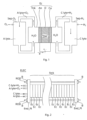
- This approach can be implemented by alkaline water electrolysis, in which electrolysis of water H 2 O is performed by flowing a direct current of electrons e- between an anode An and a cathode Ca immersed in an aqueous alkaline electrolyte, as illustrated in Figure 1 , that shows the principle of use of a conventional electrolytic cell Ec containing these elements in a tank Tnk.
- diaphragm D that is a separator nonconductive to electrons, separating the product gases and letting hydroxide ions (OH-) pass from the cathode side to the anode side.
- Ionic conductivity is supplied by the aqueous alkaline electrolyte, usually an aqueous solution of potassium hydroxide (KOH) or sodium hydroxide (NaOH).
- KOH potassium hydroxide
- NaOH sodium hydroxide
- FIG. 1 in a conventional implementation of alkaline hydrolysis, two fluidic circuits separated by the diaphragm D are employed, one comprising the anode An and the other one comprising the cathode Ca.
- the electrolyte bathing the anode is designated as "anolyte" (A-lyte in the figure), and the electrolyte bathing the cathode is designated as "catholyte" (C-lyte in the figure). It is preferable to prevent mixing between the anolyte and the catholyte to keep the product gases O 2 and H 2 as pure as possible.
- the mix comprising the anolyte A-lyte and produced oxygen gas O 2 is pumped out of the cell and goes through a first gas-liquid separator Sep-O 2 where the oxygen gas O 2 is separated from the anolyte A-lyte.
- the oxygen gas is then retrieved separately, and the anolyte sent into an anolyte tank A-Tnk before being circulated again through the tank Tnk of the cell Ec.
- the mix comprising the catholyte C-lyte and produced hydrogen gas H 2 is pumped out of the cell and goes through a second gas-liquid separator Sep-H 2 where the hydrogen gas H 2 is separated from the catholyte C-lyte.
- the hydrogen gas is then retrieved separately and the catholyte sent into a catholyte tank C-Tnk before being circulated again through the tank Tnk of the cell Ec.
- stacks Stck that can be made of several hundreds of electrolytic cells, similar in their working principle to that of Figure 1 , are employed.
- FIG. 2 illustrates an electrolyzer ELEC integrating a stack Stck made of a plurality of Electrolytic cells Ec forming each. These electrolytic cells Ec are stacked and sandwiched by two end plates End_Pl clamped by a plurality bolts B mounted onto threaded rods ROD. Inlets main channels In-MC 1 In-MC 2 , are to be input with the anolyte A-lyte and the catholyte C-lyte, respectively, while the output main channel InOut-MC 1 outputs the anolyte A-lyte and oxygen gas O 2 and the output main channel Out-MC 2 outputs the catholyte C-lyte and hydrogen gas H 2 .
- negative and positive current collectors can be placed on respective sides of the stack Stck for electrically connecting the stack to the outside.
- the anolyte and catholyte are introduced on one side of the stack Stck, at the level of a first end plate End_pl.
- the anolyte A-lyte and oxygen gas O 2 and the catholyte C-lyte and hydrogen gas H are evacuated at the same side of the stack Stck.
- the second end plate or any interposed device is configured to fluidly connect the inlets main channels In-MC 1 , In-MC 2 of the last cell ECell to the output main channel InOut-MC 1 , InOut-MC 2 of this cell.
- the end plate is electrically grounded.
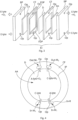
- FIG 3 illustrates the constitution of a conventional electrolytic cell Ec forming a base element of the stack Stck of figure 2 : each electrolytic cell Ec comprises a bipolar plate BP in addition to an anode catalyst An, a cathode catalyst Ca and a diaphragm D; cell frames CF are used to maintain together the other elements.
- the anode and the cathode can be formed from the catalyst layers in direct contact with the diaphragm.
- the bipolar plates are electrically conductive, are shared by two adjacent cells and separate physically these two adjacent cells while providing electrical continuity between them by transporting electrons from one cell to the next one.
- Electrolytic cells may optionally comprise porous transport layers interposed between the bipolar plates and the next ones of the anodes and/or the cathodes of a stack Stck.
- the anolyte and the catholyte are not separated, and are instead mixed as a single electrolyte E-lyte.
- the elements forming the cell are rectangularly shaped in this example, but any kind of closed shape may be employed.
- the reactants must be brought to each of the individual electrolytic cells Ec from the exterior of the stack and distributed to their respective active areas. This is performed by the means of through openings OP crossing through the thicknesses of the cell frames and the bipolar plates (or through the thickness of one or several frames holding these elements) to form manifolds extending in a stacking direction of the stacked electrolytic cells.
- the applicant studied various geometries of an element distributing the reactants of an electrochemical cell into the active area of this cell, and determined a technical solution bringing a high homogeneity to the flow distribution through the active area of the cell.
- a first aspect of the invention relates to a flow distributor configured to be part of an electrolytic cell, the flow inducer comprising: an elongated distribution chamber ; an inner wall configured to separate the distribution chamber from an active area of the electrolytic cell , the inner wall comprising a plurality of channels configured to let flow some reactant from the distribution chamber to the active area ; an outer wall, the distribution chamber being interposed between this outer wall and the inner wall ; and a duct configured to bring a reactant to the distribution chamber through the outer wall, the flow distributer further comprising a flow inducer extending from the inner wall to an inside portion of the duct, separating the distribution chamber into a left-hand side distribution chamber and a right-hand side distribution chamber, and forming a wall separating the duct into two sides.
- a primary advantage of this device is its ability to homogenize the flow of reactant of an electrochemical cell when it is properly integrated into an electrolytic cell.
- a second aspect of the invention is a cell frame configured to be part of an electrolytic cell, comprising: an opening to form an inlet manifold; and a distribution channel configured to bring some reactant from the inlet manifold toward an inner periphery of the cell frame, the cell frame being equipped with the flow distributor according to the first aspect of the invention, arranged so as to bring the reactant from the distribution channel to the distribution chamber through the duct.
- the distribution channel can be formed at a given depth within the cell frame.
- a third aspect of the invention is an electrolyzer comprising a stack of electrolytic cells each having a cell frame according to the second aspect of the invention.
- Figure 5 illustrates a inlet region In-R of a cell frame CF such as the one illustrated by Figure 4 , comprising openings Op configured to form inlet manifolds In-M 1 and In-M 2 configured to bring the reactants (anolyte and catholyte) to a cell of which the cell frame CF is part.
- Distribution channels DistCh 1 and DistCh 2 are formed within the cell frame CF, each between a respective one of the inlet manifolds In-M 1 and In-M 2 and an inner periphery IP of the cell frame, substantially in parallel with a plane defined by the cell frame taken as a whole.
- the two distribution channels are formed at two different depths in the frame cell, so that, when the cell frame CF is mounted so as to form a functional electrolytic cell, a diaphragm D is arranged within this frame at a depth Dp intermediate between the depths of formation of these two distribution channels.
- the inlet manifolds In-M 1 and In-M 2 and the respectively associated distribution channels DistCh 1 and DistCh 2 bring reactants to opposite sides of the diaphragm D.
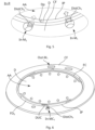
- Figure 6 represents a general view of a cell frame CF equipped with a flow distributor FD 0 at the inlet side and a flow collector FC at the outlet side of the cell frame CF, respectively.
- the elements FD and CF can be affixed to the cell frame by any conventional means, such as screws.
- the flow distributor and the flow collector have both for purpose to improve the homogeneity of the reactant flow within the active area of an electrolytic cell.
- the present invention concerns the flow distributor FD 0 , and the description will thus focus on this element, described in higher details in Figure 7 .
- Figure 7 illustrates the flow distributor FD 0 , with an elongated distribution chamber DC, arranged to follow, or to run substantially parallel to, the inner periphery IP of the cell frame CF when affixed thereto.
- An inner wall InW of the flow distributor FD 0 intended to separate the distribution chamber from an active area AA of an electrolytic cell, comprises a plurality of channels CH distributed over a length of the distribution chamber.
- One can describe the inner wall as being formed by an alignment of island-shaped projections indicated as Pr and Pr 0 on Figure 7 , two consecutive projections being separating by a gap forming one of said channels.
- An outer wall OutW of the flow distributor is arranged to be adapted to the inner periphery IP of a cell frame CF.
- the flow distributor FD 0 comprises a duct DUC designed to fluidically connect the -distribution chamber DC to an opening forming an inlet manifold via a distribution channel.
- the distribution chamber DC is to be connected to the inlet manifold In-MC 1 through the distribution channel DistCh 1 .
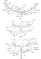
- the exit of the duct DUC faces the projection PR 0 , that comprises a protrusion forming an apex AP directed toward the exit of the duct DUC and is configured to separate incoming flow into two equal sub-flows, respectively redirected toward a left-hand side LHS-DC and a right-hand side RHS-DC of the distribution chamber DC.
- Figure 8 shows a magnification of an inlet section InSec of the flow distributor FD 0 , with some details of the duct DUC: going from the outer wall OutW of the flow distributor FD 0 to the distribution chamber, it comprises a narrowing section NR (see Figure 7 ) leading to a first straight portion SP1 having an orientation towards the outer wall OutW and then to a second straight portion SP2 leading towards the apex AP of the projection Pr0.
- the first straight portion SP1 and the second straight portion SP2 are connected by a bent portion BP.
- the flow distributor FD 0 is preferably made from an electrically insulating material such as a polymer, to limit the risk of shorting the electrodes and to maintain the cost low as compared to metal-based frames and rings.
- the material used preferably resists to the pressure, temperature and chemical environment of the hydrogen electrolysis process. Therefore, it is preferable that the flow distributor resist to pressure as high as 120 bars, temperatures up to 120°C, and to alkaline environments, the electrolyte being typically alkaline KOH- or NaOH-based solutions.
- FIG 9 illustrates an input section InSec of an enhanced flow distributor FD 1 .
- the flow distributor FD 1 is similar to the flow distributor FD 0 , so that the description made so far of the flow distributor FD 0 applies to the flow distributor FD 1 , at the exception of the following point: instead of forming the apex AP directed toward the exit of the duct DUC, a protrusion of the projection PR 0 extends to form a flow inducer IND, that is a wall extending from the distribution chamber into an inside portion of the duct DUC, in this example into the first straight portion SP1 of the duct DUC, arranged so that a flow InFl of reactant incoming from the narrowing portion NR is separated into two portions as illustrated in Figure 9 , preferably having sensibly equal flow rates.
- a flow inducer IND that is a wall extending from the distribution chamber into an inside portion of the duct DUC, in this example into the first straight portion SP1 of the duct DUC, arranged so that
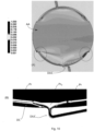
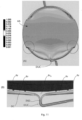
- Figure 11 represents results of a flow simulation in an electrolytic cell based on the geometry of the cell frame of Figure 6 , equipped with a flow distributor FD 1 of figures 7 and 9 .
- the scale represents phase velocity of a fluid flowing through the electrolytic cell, between 0.001 and 1.000 m.s -2 .
- A a general view of the active area is represented, showing a substantially symmetrical flow distribution between a left-hand side and a right-hand side of the cell. The imbalance that was highlighted in the circle portions of Figure 10 has been substantially reduced if not totally suppressed.
- the input section InSect is magnified, and we can see that the flow is already symmetric inside of the duct DUC.
- cell frame taken in example is presenting a circular shape, this does form a limitation and a cell frame according to the invention may present any practicable shape, such as a square or rectangular shape, such as in the configuration illustrated by figure 2 .
- the cell frame and the flow distributors FD 0 and FD 1 are presented as two distinct elements to be affixed to one another.
- the cell frame may be shaped so as incorporate a flow distributor in one piece. In both cases, it can be said that the cell framed is equipped with the flow distributor.
Landscapes
- Chemical & Material Sciences (AREA)
- Engineering & Computer Science (AREA)
- Chemical Kinetics & Catalysis (AREA)
- Electrochemistry (AREA)
- Materials Engineering (AREA)
- Metallurgy (AREA)
- Organic Chemistry (AREA)
- Inorganic Chemistry (AREA)
- Electrolytic Production Of Non-Metals, Compounds, Apparatuses Therefor (AREA)
Priority Applications (3)
| Application Number | Priority Date | Filing Date | Title |
|---|---|---|---|
| EP23315388.1A EP4538426A1 (fr) | 2023-10-13 | 2023-10-13 | Distributeur de flux conçu pour distribuer de manière homogène des réactifs dans une cellule électrolytique, cadre de cellule le comprenant et électrolyseur comprenant le cadre de cellule |
| CN202480064892.3A CN122029309A (zh) | 2023-10-13 | 2024-10-09 | 被构造用于将反应物均匀地分配到电解槽中的分流器、包括其的电解槽极框和包括该电解槽极框的电解器 |
| PCT/EP2024/078364 WO2025078414A1 (fr) | 2023-10-13 | 2024-10-09 | Répartiteur d'écoulement configuré pour répartir de manière homogène des réactifs dans une cellule électrolytique, cadre de cellule le comprenant, et électrolyseur comprenant le cadre de cellule |
Applications Claiming Priority (1)
| Application Number | Priority Date | Filing Date | Title |
|---|---|---|---|
| EP23315388.1A EP4538426A1 (fr) | 2023-10-13 | 2023-10-13 | Distributeur de flux conçu pour distribuer de manière homogène des réactifs dans une cellule électrolytique, cadre de cellule le comprenant et électrolyseur comprenant le cadre de cellule |
Publications (1)
| Publication Number | Publication Date |
|---|---|
| EP4538426A1 true EP4538426A1 (fr) | 2025-04-16 |
Family
ID=88833793
Family Applications (1)
| Application Number | Title | Priority Date | Filing Date |
|---|---|---|---|
| EP23315388.1A Pending EP4538426A1 (fr) | 2023-10-13 | 2023-10-13 | Distributeur de flux conçu pour distribuer de manière homogène des réactifs dans une cellule électrolytique, cadre de cellule le comprenant et électrolyseur comprenant le cadre de cellule |
Country Status (3)
| Country | Link |
|---|---|
| EP (1) | EP4538426A1 (fr) |
| CN (1) | CN122029309A (fr) |
| WO (1) | WO2025078414A1 (fr) |
Citations (5)
| Publication number | Priority date | Publication date | Assignee | Title |
|---|---|---|---|---|
| US6117287A (en) | 1998-05-26 | 2000-09-12 | Proton Energy Systems, Inc. | Electrochemical cell frame |
| US6852205B1 (en) | 1999-09-27 | 2005-02-08 | Shinko-Pantec Co., Ltd. | Water-electrolysis-device-use electrode plate, unit, solid electrolytic membrane unit and electrolytic cell |
| US20160115603A1 (en) * | 2014-10-24 | 2016-04-28 | Swiss Hydrogen Sa | Electrochemical stack device |
| KR20200024019A (ko) * | 2018-08-27 | 2020-03-06 | 한국에너지기술연구원 | 알칼라인 수전해 셀 조립체 |
| EP3696298A1 (fr) | 2019-02-18 | 2020-08-19 | Zentrum für Sonnenenergie- und Wasserstoff-Forschung Baden-Württemberg | Bloc d'électrolyse et cadre pour cellule correspondant |
-
2023
- 2023-10-13 EP EP23315388.1A patent/EP4538426A1/fr active Pending
-
2024
- 2024-10-09 CN CN202480064892.3A patent/CN122029309A/zh active Pending
- 2024-10-09 WO PCT/EP2024/078364 patent/WO2025078414A1/fr not_active Ceased
Patent Citations (5)
| Publication number | Priority date | Publication date | Assignee | Title |
|---|---|---|---|---|
| US6117287A (en) | 1998-05-26 | 2000-09-12 | Proton Energy Systems, Inc. | Electrochemical cell frame |
| US6852205B1 (en) | 1999-09-27 | 2005-02-08 | Shinko-Pantec Co., Ltd. | Water-electrolysis-device-use electrode plate, unit, solid electrolytic membrane unit and electrolytic cell |
| US20160115603A1 (en) * | 2014-10-24 | 2016-04-28 | Swiss Hydrogen Sa | Electrochemical stack device |
| KR20200024019A (ko) * | 2018-08-27 | 2020-03-06 | 한국에너지기술연구원 | 알칼라인 수전해 셀 조립체 |
| EP3696298A1 (fr) | 2019-02-18 | 2020-08-19 | Zentrum für Sonnenenergie- und Wasserstoff-Forschung Baden-Württemberg | Bloc d'électrolyse et cadre pour cellule correspondant |
Also Published As
| Publication number | Publication date |
|---|---|
| WO2025078414A1 (fr) | 2025-04-17 |
| CN122029309A (zh) | 2026-05-12 |
Similar Documents
| Publication | Publication Date | Title |
|---|---|---|
| US10273586B2 (en) | Electrochemical cell | |
| CA2914112C (fr) | Cellule d'electrolyse des solutions alcalines | |
| CN106030882B (zh) | 具有保护衬垫布置的电化学电池 | |
| WO2022156869A1 (fr) | Système d'électrolyse | |
| CN115989343A (zh) | 用于单极电化学装置的组合式电流载体、循环腔和框架 | |
| KR101895525B1 (ko) | 역전기투석 장치를 이용한 저 에너지 소비형 수산화나트륨 생산 장치 및 이를 이용한 하이브리드 시스템 | |
| EP4497844B1 (fr) | Cadre multi-électrode de boîtier-cellule pour électrolyseur d'hydrogène, électrolyseur le comprenant et procédé de fabrication | |
| US20240014413A1 (en) | Bipolar plate for an electrochemical cell, arrangement of electrochemical cells, and method for operating said arrangement of electrochemical cells | |
| US5637204A (en) | End casing for an electrodialyzer electrodialyzer equipped with such a casing and use of the said electrodialyzer | |
| US20250075346A1 (en) | Cassette for electrolyzer of a four plate construction | |
| EP4621098A1 (fr) | Electrolyseur pour la production d'hydrogène et procédé pour la production d'hydrogène | |
| US12297547B2 (en) | Compressible flow distribution system for electrolyzer plates | |
| GB2613332A (en) | Memrane-less electrolyser cell utilising carbon nanotubes | |
| EP4343027A1 (fr) | Électrolyseur destiné à la production d'hydrogène et procédé de production d'hydrogène et utilisation de l'électrolyseur | |
| WO2025078414A1 (fr) | Répartiteur d'écoulement configuré pour répartir de manière homogène des réactifs dans une cellule électrolytique, cadre de cellule le comprenant, et électrolyseur comprenant le cadre de cellule | |
| US20250034726A1 (en) | Cassette for electrolyzer with outlet blockade with drain | |
| EP4728576A1 (fr) | Cellule électrochimique | |
| EP4686773A1 (fr) | Cadre de cellule mince à canaux ouverts pour électrolyseur d'hydrogène, empilement de ce cadre de cellule et électrolyseur comprenant un tel empilement | |
| EP4686774A1 (fr) | Cadre de cellule mince pour électrolyseur d'hydrogène, empilement de ce cadre de cellule et électrolyseur comprenant un tel empilement | |
| US20250297380A1 (en) | Electrolyzer for producing hydrogen and method for the production of hydrogen, and use of the electrolyser | |
| NL2033470B1 (en) | Cell for forming an electrolyser, electrolyser comprising such cell, method for manufacturing and operating an electrolyser | |
| CN218989422U (zh) | 一种双隔膜次氯酸钠电解槽 | |
| WO2025223961A1 (fr) | Cellule d'électrolyse et empilement de cellules d'électrolyse présentant une efficacité de courant vagabond améliorée | |
| WO2026093015A1 (fr) | Ensemble plaque d'électrode pour unité électrolytique, unité électrolytique et empilement électrolytique | |
| CN116676610A (zh) | 电化学装置 |
Legal Events
| Date | Code | Title | Description |
|---|---|---|---|
| PUAI | Public reference made under article 153(3) epc to a published international application that has entered the european phase |
Free format text: ORIGINAL CODE: 0009012 |
|
| STAA | Information on the status of an ep patent application or granted ep patent |
Free format text: STATUS: THE APPLICATION HAS BEEN PUBLISHED |
|
| AK | Designated contracting states |
Kind code of ref document: A1 Designated state(s): AL AT BE BG CH CY CZ DE DK EE ES FI FR GB GR HR HU IE IS IT LI LT LU LV MC ME MK MT NL NO PL PT RO RS SE SI SK SM TR |
|
| RIN1 | Information on inventor provided before grant (corrected) |
Inventor name: BALDUZZI, FRANCESCO Inventor name: BIANCHINI, ALESSANDRO Inventor name: HOSSAIN, SYED SAHIL Inventor name: FERRO, FRANCESCO MARIA Inventor name: NEBEN, MATTHIAS |
|
| STAA | Information on the status of an ep patent application or granted ep patent |
Free format text: STATUS: REQUEST FOR EXAMINATION WAS MADE |
|
| 17P | Request for examination filed |
Effective date: 20251013 |
|
| RAP1 | Party data changed (applicant data changed or rights of an application transferred) |
Owner name: JOHN COCKERILL HYDROGEN FRANCE SAS Owner name: UNIVERSITE DE FLORENCE |
|
| RAP3 | Party data changed (applicant data changed or rights of an application transferred) |
Owner name: JOHN COCKERILL HYDROGEN FRANCE Owner name: UNIVERSITE DE FLORENCE |
|
| GRAP | Despatch of communication of intention to grant a patent |
Free format text: ORIGINAL CODE: EPIDOSNIGR1 |
|
| STAA | Information on the status of an ep patent application or granted ep patent |
Free format text: STATUS: GRANT OF PATENT IS INTENDED |
|
| INTG | Intention to grant announced |
Effective date: 20260521 |