EP4538430A1 - Gasversorgungsvorrichtung - Google Patents
Gasversorgungsvorrichtung Download PDFInfo
- Publication number
- EP4538430A1 EP4538430A1 EP23803651.1A EP23803651A EP4538430A1 EP 4538430 A1 EP4538430 A1 EP 4538430A1 EP 23803651 A EP23803651 A EP 23803651A EP 4538430 A1 EP4538430 A1 EP 4538430A1
- Authority
- EP
- European Patent Office
- Prior art keywords
- evaporator
- shell
- mixed gas
- gas
- carrier gas
- Prior art date
- Legal status (The legal status is an assumption and is not a legal conclusion. Google has not performed a legal analysis and makes no representation as to the accuracy of the status listed.)
- Pending
Links
Images

Classifications
-
- B—PERFORMING OPERATIONS; TRANSPORTING
- B01—PHYSICAL OR CHEMICAL PROCESSES OR APPARATUS IN GENERAL
- B01J—CHEMICAL OR PHYSICAL PROCESSES, e.g. CATALYSIS OR COLLOID CHEMISTRY; THEIR RELEVANT APPARATUS
- B01J7/00—Apparatus for generating gases
- B01J7/02—Apparatus for generating gases by wet methods
-
- B—PERFORMING OPERATIONS; TRANSPORTING
- B01—PHYSICAL OR CHEMICAL PROCESSES OR APPARATUS IN GENERAL
- B01D—SEPARATION
- B01D1/00—Evaporating
- B01D1/04—Evaporators with horizontal tubes
-
- B—PERFORMING OPERATIONS; TRANSPORTING
- B01—PHYSICAL OR CHEMICAL PROCESSES OR APPARATUS IN GENERAL
- B01D—SEPARATION
- B01D1/00—Evaporating
- B01D1/14—Evaporating with heated gases or vapours or liquids in contact with the liquid
-
- B—PERFORMING OPERATIONS; TRANSPORTING
- B01—PHYSICAL OR CHEMICAL PROCESSES OR APPARATUS IN GENERAL
- B01D—SEPARATION
- B01D3/00—Distillation or related exchange processes in which liquids are contacted with gaseous media, e.g. stripping
- B01D3/34—Distillation or related exchange processes in which liquids are contacted with gaseous media, e.g. stripping with one or more auxiliary substances
- B01D3/343—Distillation or related exchange processes in which liquids are contacted with gaseous media, e.g. stripping with one or more auxiliary substances the substance being a gas
-
- C—CHEMISTRY; METALLURGY
- C23—COATING METALLIC MATERIAL; COATING MATERIAL WITH METALLIC MATERIAL; CHEMICAL SURFACE TREATMENT; DIFFUSION TREATMENT OF METALLIC MATERIAL; COATING BY VACUUM EVAPORATION, BY SPUTTERING, BY ION IMPLANTATION OR BY CHEMICAL VAPOUR DEPOSITION, IN GENERAL; INHIBITING CORROSION OF METALLIC MATERIAL OR INCRUSTATION IN GENERAL
- C23C—COATING METALLIC MATERIAL; COATING MATERIAL WITH METALLIC MATERIAL; SURFACE TREATMENT OF METALLIC MATERIAL BY DIFFUSION INTO THE SURFACE, BY CHEMICAL CONVERSION OR SUBSTITUTION; COATING BY VACUUM EVAPORATION, BY SPUTTERING, BY ION IMPLANTATION OR BY CHEMICAL VAPOUR DEPOSITION, IN GENERAL
- C23C16/00—Chemical coating by decomposition of gaseous compounds, without leaving reaction products of surface material in the coating, i.e. chemical vapour deposition [CVD] processes
- C23C16/44—Chemical coating by decomposition of gaseous compounds, without leaving reaction products of surface material in the coating, i.e. chemical vapour deposition [CVD] processes characterised by the method of coating
- C23C16/448—Chemical coating by decomposition of gaseous compounds, without leaving reaction products of surface material in the coating, i.e. chemical vapour deposition [CVD] processes characterised by the method of coating characterised by the method used for generating reactive gas streams, e.g. by evaporation or sublimation of precursor materials
-
- C—CHEMISTRY; METALLURGY
- C23—COATING METALLIC MATERIAL; COATING MATERIAL WITH METALLIC MATERIAL; CHEMICAL SURFACE TREATMENT; DIFFUSION TREATMENT OF METALLIC MATERIAL; COATING BY VACUUM EVAPORATION, BY SPUTTERING, BY ION IMPLANTATION OR BY CHEMICAL VAPOUR DEPOSITION, IN GENERAL; INHIBITING CORROSION OF METALLIC MATERIAL OR INCRUSTATION IN GENERAL
- C23C—COATING METALLIC MATERIAL; COATING MATERIAL WITH METALLIC MATERIAL; SURFACE TREATMENT OF METALLIC MATERIAL BY DIFFUSION INTO THE SURFACE, BY CHEMICAL CONVERSION OR SUBSTITUTION; COATING BY VACUUM EVAPORATION, BY SPUTTERING, BY ION IMPLANTATION OR BY CHEMICAL VAPOUR DEPOSITION, IN GENERAL
- C23C16/00—Chemical coating by decomposition of gaseous compounds, without leaving reaction products of surface material in the coating, i.e. chemical vapour deposition [CVD] processes
- C23C16/44—Chemical coating by decomposition of gaseous compounds, without leaving reaction products of surface material in the coating, i.e. chemical vapour deposition [CVD] processes characterised by the method of coating
- C23C16/448—Chemical coating by decomposition of gaseous compounds, without leaving reaction products of surface material in the coating, i.e. chemical vapour deposition [CVD] processes characterised by the method of coating characterised by the method used for generating reactive gas streams, e.g. by evaporation or sublimation of precursor materials
- C23C16/4481—Chemical coating by decomposition of gaseous compounds, without leaving reaction products of surface material in the coating, i.e. chemical vapour deposition [CVD] processes characterised by the method of coating characterised by the method used for generating reactive gas streams, e.g. by evaporation or sublimation of precursor materials by evaporation using carrier gas in contact with the source material
-
- C—CHEMISTRY; METALLURGY
- C23—COATING METALLIC MATERIAL; COATING MATERIAL WITH METALLIC MATERIAL; CHEMICAL SURFACE TREATMENT; DIFFUSION TREATMENT OF METALLIC MATERIAL; COATING BY VACUUM EVAPORATION, BY SPUTTERING, BY ION IMPLANTATION OR BY CHEMICAL VAPOUR DEPOSITION, IN GENERAL; INHIBITING CORROSION OF METALLIC MATERIAL OR INCRUSTATION IN GENERAL
- C23C—COATING METALLIC MATERIAL; COATING MATERIAL WITH METALLIC MATERIAL; SURFACE TREATMENT OF METALLIC MATERIAL BY DIFFUSION INTO THE SURFACE, BY CHEMICAL CONVERSION OR SUBSTITUTION; COATING BY VACUUM EVAPORATION, BY SPUTTERING, BY ION IMPLANTATION OR BY CHEMICAL VAPOUR DEPOSITION, IN GENERAL
- C23C16/00—Chemical coating by decomposition of gaseous compounds, without leaving reaction products of surface material in the coating, i.e. chemical vapour deposition [CVD] processes
- C23C16/44—Chemical coating by decomposition of gaseous compounds, without leaving reaction products of surface material in the coating, i.e. chemical vapour deposition [CVD] processes characterised by the method of coating
- C23C16/448—Chemical coating by decomposition of gaseous compounds, without leaving reaction products of surface material in the coating, i.e. chemical vapour deposition [CVD] processes characterised by the method of coating characterised by the method used for generating reactive gas streams, e.g. by evaporation or sublimation of precursor materials
- C23C16/452—Chemical coating by decomposition of gaseous compounds, without leaving reaction products of surface material in the coating, i.e. chemical vapour deposition [CVD] processes characterised by the method of coating characterised by the method used for generating reactive gas streams, e.g. by evaporation or sublimation of precursor materials by activating reactive gas streams before their introduction into the reaction chamber, e.g. by ionisation or addition of reactive species
-
- C—CHEMISTRY; METALLURGY
- C23—COATING METALLIC MATERIAL; COATING MATERIAL WITH METALLIC MATERIAL; CHEMICAL SURFACE TREATMENT; DIFFUSION TREATMENT OF METALLIC MATERIAL; COATING BY VACUUM EVAPORATION, BY SPUTTERING, BY ION IMPLANTATION OR BY CHEMICAL VAPOUR DEPOSITION, IN GENERAL; INHIBITING CORROSION OF METALLIC MATERIAL OR INCRUSTATION IN GENERAL
- C23C—COATING METALLIC MATERIAL; COATING MATERIAL WITH METALLIC MATERIAL; SURFACE TREATMENT OF METALLIC MATERIAL BY DIFFUSION INTO THE SURFACE, BY CHEMICAL CONVERSION OR SUBSTITUTION; COATING BY VACUUM EVAPORATION, BY SPUTTERING, BY ION IMPLANTATION OR BY CHEMICAL VAPOUR DEPOSITION, IN GENERAL
- C23C16/00—Chemical coating by decomposition of gaseous compounds, without leaving reaction products of surface material in the coating, i.e. chemical vapour deposition [CVD] processes
- C23C16/44—Chemical coating by decomposition of gaseous compounds, without leaving reaction products of surface material in the coating, i.e. chemical vapour deposition [CVD] processes characterised by the method of coating
- C23C16/455—Chemical coating by decomposition of gaseous compounds, without leaving reaction products of surface material in the coating, i.e. chemical vapour deposition [CVD] processes characterised by the method of coating characterised by the method used for introducing gases into reaction chamber or for modifying gas flows in reaction chamber
- C23C16/45561—Gas plumbing upstream of the reaction chamber
-
- C—CHEMISTRY; METALLURGY
- C30—CRYSTAL GROWTH
- C30B—SINGLE-CRYSTAL GROWTH; UNIDIRECTIONAL SOLIDIFICATION OF EUTECTIC MATERIAL OR UNIDIRECTIONAL DEMIXING OF EUTECTOID MATERIAL; REFINING BY ZONE-MELTING OF MATERIAL; PRODUCTION OF A HOMOGENEOUS POLYCRYSTALLINE MATERIAL WITH DEFINED STRUCTURE; SINGLE CRYSTALS OR HOMOGENEOUS POLYCRYSTALLINE MATERIAL WITH DEFINED STRUCTURE; AFTER-TREATMENT OF SINGLE CRYSTALS OR A HOMOGENEOUS POLYCRYSTALLINE MATERIAL WITH DEFINED STRUCTURE; APPARATUS THEREFOR
- C30B25/00—Single-crystal growth by chemical reaction of reactive gases, e.g. chemical vapour-deposition growth
- C30B25/02—Epitaxial-layer growth
- C30B25/14—Feed and outlet means for the gases; Modifying the flow of the reactive gases
-
- C—CHEMISTRY; METALLURGY
- C30—CRYSTAL GROWTH
- C30B—SINGLE-CRYSTAL GROWTH; UNIDIRECTIONAL SOLIDIFICATION OF EUTECTIC MATERIAL OR UNIDIRECTIONAL DEMIXING OF EUTECTOID MATERIAL; REFINING BY ZONE-MELTING OF MATERIAL; PRODUCTION OF A HOMOGENEOUS POLYCRYSTALLINE MATERIAL WITH DEFINED STRUCTURE; SINGLE CRYSTALS OR HOMOGENEOUS POLYCRYSTALLINE MATERIAL WITH DEFINED STRUCTURE; AFTER-TREATMENT OF SINGLE CRYSTALS OR A HOMOGENEOUS POLYCRYSTALLINE MATERIAL WITH DEFINED STRUCTURE; APPARATUS THEREFOR
- C30B29/00—Single crystals or homogeneous polycrystalline material with defined structure characterised by the material or by their shape
- C30B29/02—Elements
- C30B29/06—Silicon
-
- F—MECHANICAL ENGINEERING; LIGHTING; HEATING; WEAPONS; BLASTING
- F28—HEAT EXCHANGE IN GENERAL
- F28C—HEAT-EXCHANGE APPARATUS, NOT PROVIDED FOR IN ANOTHER SUBCLASS, IN WHICH THE HEAT-EXCHANGE MEDIA COME INTO DIRECT CONTACT WITHOUT CHEMICAL INTERACTION
- F28C3/00—Other direct-contact heat-exchange apparatus
- F28C3/06—Other direct-contact heat-exchange apparatus the heat-exchange media being a liquid and a gas or vapour
- F28C3/08—Other direct-contact heat-exchange apparatus the heat-exchange media being a liquid and a gas or vapour with change of state, e.g. absorption, evaporation, condensation
-
- F—MECHANICAL ENGINEERING; LIGHTING; HEATING; WEAPONS; BLASTING
- F28—HEAT EXCHANGE IN GENERAL
- F28D—HEAT-EXCHANGE APPARATUS, NOT PROVIDED FOR IN ANOTHER SUBCLASS, IN WHICH THE HEAT-EXCHANGE MEDIA DO NOT COME INTO DIRECT CONTACT
- F28D7/00—Heat-exchange apparatus having stationary tubular conduit assemblies for both heat-exchange media, the media being in contact with different sides of a conduit wall
- F28D7/16—Heat-exchange apparatus having stationary tubular conduit assemblies for both heat-exchange media, the media being in contact with different sides of a conduit wall the conduits being arranged in parallel spaced relation
Definitions
- the present invention relates to a gas supply device, and more specifically to a gas supply device useful for supplying a mixed gas, often used in the semiconductor industry and the like, that is composed of a trichlorosilane gas and a hydrogen gas.
- liquid trichlorosilane and a hydrogen gas are introduced into an evaporator (Patent Document 2 and Patent Document 3).
- the evaporator the liquid trichlorosilane is vaporized while the hydrogen gas is being bubbled to generate the mixed gas that is composed of the trichlorosilane gas and the hydrogen gas.
- the present invention provides a mixed gas supply device including:
- the evaporator can be downsized, the entire mixed gas supply device can have a compact configuration, and the supply amount of the mixed gas can be made stable by performing stringent fluid level control in the shell of the evaporator.
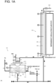
- the evaporator 10 is supplied with liquid trichlorosilane as a liquid component and a hydrogen gas as a carrier gas. By heating these components, the evaporator 10 vaporizes the liquid trichlorosilane to produce a trichlorosilane gas and generates a mixed gas that is composed of the trichlorosilane gas serving as a component gas and the hydrogen gas. In this mixed gas, trichlorosilane is in a supersaturated state.
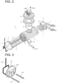
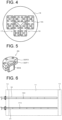
- the carrier gas tubes 16 and 17 extend in the direction of the axis A from the tube plate 14 toward the opposed tube plate 13 in the vicinity of the bottom of the shell 11 and so as to be parallel to some of the lower tubes, out of the multiple heating medium tubes 12, thereby reaching the vicinity of the tube plate 13.
- the carrier gas tubes 16 and 17 extend linearly from the tube plate 14 toward the tube plate 13 opposed to the tube plate 14 in the present embodiment, the present invention is not limited thereto.
- the number of the carrier gas tubes may be three or more, and the carrier gas tubes may be bent.
- the flow path of the heating medium travels in a reciprocating manner between the opposed tube plates 13 and 14 by means of the heating medium tubes 12 and the tube plate grooves 13A and 14A.
- the liquid trichlorosilane condensed in the cooler 30 is also supplied into the shell 11 by flowing through a pipe 37, the evaporator lower end valve 21, and the liquid component supply port 20.
- the liquid quantity in the shell 11 is detected and properly controlled by providing a fluid level measuring instrument between the liquid component supply port 20 and the lower end of the cooler 30.
- a discharge port 23 and the liquid component supply port 20 of the evaporator 10 are connected via a connecting tube 40, and a level sensor L is provided inside the connecting tube 40.
- the fluid level detected by the level sensor L is made to be within a predetermined range that is above all the heating medium tubes 12 in the shell 11.
- the detected fluid level is preferably made to be within a range in which the fluctuation range of the fluid level is within 10% of the upper limit of the fluid level, and more preferably as stable as possible.
- the low-pressure automatic valve 41 automatically opens, and the liquid trichlorosilane is supplied into the liquid component supply port 20 at a flow rate that prevents the fluid level in the shell 11 from fluctuating, which is controlled by the needle valve 42.
- the needle valve 42 is provided upstream of the low-pressure automatic valve 41, the liquid stored between the needle valve 42 and the low-pressure automatic valve 41 may flow into the shell 11 all at once when the low-pressure automatic valve 41 opens, causing the fluid level in the shell 11 to fluctuate, which is not preferable.
- the heat transfer amount from the heating medium tubes 12 to the liquid trichlorosilane will be constant, the evaporation amount of the liquid trichlorosilane will be stable, and the discharge amount of the mixed gas will be stable.
- the evaporation amount of the liquid trichlorosilane cannot be made stable, and the discharge amount of the mixed gas will not be stable.
- an appropriate sealing member is preferably interposed between the two flanges 33F1 and 33F2.
- the observation window 33 preferably has a diameter of 20 to 40 mm . This facilitates visual observation of a bubbling state of the carrier gas inside the shell 11.
- the aforementioned pipe 31 is provided with a gate valve 34.
- the mixed gas supply devices 1A and 1B are not categorized as a "pressure vessel" stipulated by laws and regulations and are easy to handle.
- the mixed gas discharged from the discharge port 23 of the evaporator 10 is supplied to a lower end portion 39 of the cooler 30 through the pipe 31.
- the concentration of the component gas at a concentration regulated gas supply port 38 is determined by the pressure and the condensation temperature of the system, the temperature of the refrigerant supplied to the upper stage of the cooler 30 is preferably kept within a predetermined range (preferably, ⁇ 0.1°C) by a chiller.
- an observation window 43 for observing the inside of the lower end portion of the cooler may be provided at the lower end portion 39 of the cooler 30 as illustrated in Fig. 1B .
- the configuration of the observation window 43 can be made similar to that of the observation window 33 provided on the discharge port 23 of the evaporator 10.
- the liquid trichlorosilane that has been condensed and separated flows from the lower end portion of the cooler 30 through the pipe 37 and is fed to the liquid component supply port 20 of the evaporator 10.
Landscapes
- Chemical & Material Sciences (AREA)
- Engineering & Computer Science (AREA)
- Chemical Kinetics & Catalysis (AREA)
- Organic Chemistry (AREA)
- Mechanical Engineering (AREA)
- Materials Engineering (AREA)
- Metallurgy (AREA)
- General Chemical & Material Sciences (AREA)
- General Engineering & Computer Science (AREA)
- Crystallography & Structural Chemistry (AREA)
- Physics & Mathematics (AREA)
- Thermal Sciences (AREA)
- Chemical Vapour Deposition (AREA)
- Heat-Exchange Devices With Radiators And Conduit Assemblies (AREA)
- Feeding, Discharge, Calcimining, Fusing, And Gas-Generation Devices (AREA)
- Crystals, And After-Treatments Of Crystals (AREA)
- Silicon Compounds (AREA)
Applications Claiming Priority (2)
| Application Number | Priority Date | Filing Date | Title |
|---|---|---|---|
| JP2022077155A JP7127792B1 (ja) | 2022-05-09 | 2022-05-09 | ガス供給装置 |
| PCT/JP2023/023767 WO2023219179A1 (ja) | 2022-05-09 | 2023-06-27 | ガス供給装置 |
Publications (2)
| Publication Number | Publication Date |
|---|---|
| EP4538430A1 true EP4538430A1 (de) | 2025-04-16 |
| EP4538430A4 EP4538430A4 (de) | 2026-03-11 |
Family
ID=83103179
Family Applications (1)
| Application Number | Title | Priority Date | Filing Date |
|---|---|---|---|
| EP23803651.1A Pending EP4538430A4 (de) | 2022-05-09 | 2023-06-27 | Gasversorgungsvorrichtung |
Country Status (6)
| Country | Link |
|---|---|
| US (1) | US20240316517A1 (de) |
| EP (1) | EP4538430A4 (de) |
| JP (2) | JP7127792B1 (de) |
| KR (1) | KR102795853B1 (de) |
| CN (1) | CN117897520A (de) |
| WO (1) | WO2023219179A1 (de) |
Families Citing this family (1)
| Publication number | Priority date | Publication date | Assignee | Title |
|---|---|---|---|---|
| JP7127792B1 (ja) * | 2022-05-09 | 2022-08-30 | 東横化学株式会社 | ガス供給装置 |
Family Cites Families (14)
| Publication number | Priority date | Publication date | Assignee | Title |
|---|---|---|---|---|
| US4322265A (en) * | 1980-06-03 | 1982-03-30 | Maloney-Crawford Corporation | Atmospheric glycol reclaimer with vapor recycle |
| JP3156858B2 (ja) * | 1991-07-09 | 2001-04-16 | 東芝セラミックス株式会社 | 液体原料供給装置 |
| US5330624A (en) * | 1991-12-27 | 1994-07-19 | Phillips Petroleum Company | Fractionator-reboiler sludge removal system and method |
| JP3770409B2 (ja) * | 1995-01-06 | 2006-04-26 | 東京エレクトロン株式会社 | Hmds供給装置 |
| JP4505077B2 (ja) * | 1999-04-30 | 2010-07-14 | Sumco Techxiv株式会社 | トリクロロシランガス気化供給装置 |
| JP4542643B2 (ja) | 1999-08-30 | 2010-09-15 | Sumco Techxiv株式会社 | ガス供給装置およびガス供給方法 |
| JP2009038047A (ja) * | 2006-04-26 | 2009-02-19 | Entegris Inc | 液体気化装置 |
| JP2008124356A (ja) * | 2006-11-15 | 2008-05-29 | Sekisui Chem Co Ltd | 表面処理方法及び装置 |
| JP5473421B2 (ja) * | 2009-06-15 | 2014-04-16 | ヘンミ計算尺株式会社 | 液体原料のバブリング気化供給方法及び装置 |
| JP5584885B2 (ja) * | 2010-06-14 | 2014-09-10 | 柴田科学株式会社 | ガス発生装置用熱交換器及びガス発生装置 |
| HUP1100435A2 (en) * | 2011-08-12 | 2013-04-29 | Hyd Rakkutato Es Gyogyszerfejlesztoe Kft | Apparatus and method for distillation of liquids with different boiling point |
| JP2013115208A (ja) * | 2011-11-28 | 2013-06-10 | Tokyo Electron Ltd | 気化原料供給装置、これを備える基板処理装置、及び気化原料供給方法 |
| US10480071B2 (en) * | 2013-07-26 | 2019-11-19 | Techno Boundary Co. | Continuous distillation trichlorosilane vaporization supply apparatus |
| JP7127792B1 (ja) * | 2022-05-09 | 2022-08-30 | 東横化学株式会社 | ガス供給装置 |
-
2022
- 2022-05-09 JP JP2022077155A patent/JP7127792B1/ja active Active
- 2022-08-08 JP JP2022126554A patent/JP7765012B2/ja active Active
-
2023
- 2023-06-27 WO PCT/JP2023/023767 patent/WO2023219179A1/ja not_active Ceased
- 2023-06-27 US US18/575,556 patent/US20240316517A1/en active Pending
- 2023-06-27 CN CN202380013099.6A patent/CN117897520A/zh active Pending
- 2023-06-27 KR KR1020247002118A patent/KR102795853B1/ko active Active
- 2023-06-27 EP EP23803651.1A patent/EP4538430A4/de active Pending
Also Published As
| Publication number | Publication date |
|---|---|
| KR102795853B1 (ko) | 2025-04-14 |
| US20240316517A1 (en) | 2024-09-26 |
| JP7765012B2 (ja) | 2025-11-06 |
| KR20250002090A (ko) | 2025-01-07 |
| JP2023166240A (ja) | 2023-11-21 |
| CN117897520A (zh) | 2024-04-16 |
| JP7127792B1 (ja) | 2022-08-30 |
| JP2023166319A (ja) | 2023-11-21 |
| EP4538430A4 (de) | 2026-03-11 |
| WO2023219179A1 (ja) | 2023-11-16 |
Similar Documents
| Publication | Publication Date | Title |
|---|---|---|
| EP4538430A1 (de) | Gasversorgungsvorrichtung | |
| CN105659359B (zh) | 连续蒸馏式三氯氢硅气化供给装置 | |
| US8490506B2 (en) | In-situ gas analyzer probe | |
| KR20080110603A (ko) | 액체재료 기화장치 | |
| KR20160076430A (ko) | 기화 시스템 | |
| JPH0847629A (ja) | 液体原料ガスの供給方法および装置 | |
| KR100247679B1 (ko) | 액체 소스로 부터 발생된 화학 증기의 통합형 전송장치의 화학증기 전송 모듈 | |
| KR20160076431A (ko) | 유체 가열기 | |
| Abraham et al. | Experimental studies on thermal spray-coated horizontal tubes for falling film evaporation in multi-effect desalination system | |
| US5254310A (en) | High temperature generalized corrosion test installation | |
| MX2025015285A (es) | Sistema de refrigeracion para la refrigeracion por inmersion liquida de componentes electronicos | |
| JP6843988B2 (ja) | 排気測定装置用凝縮水排出システム | |
| TWI870912B (zh) | 氣體供給裝置 | |
| Bartolini et al. | Experimental study on nucleate boiling of water in vertical upflow and downflow | |
| CN111013415A (zh) | 基于温度控制的标准气体发生系统 | |
| ITMI20000176A1 (it) | Dispositivo ebulliometrico per misurare con elevata precisione un parametro fisico di sostanze liquide | |
| JP4664745B2 (ja) | 加圧式マイクロリアクタシステム | |
| US9885113B2 (en) | Vaporizer, center rod used therein, and method for vaporizing material carried by carrier gas | |
| CN211170883U (zh) | 气体供应系统 | |
| Honda et al. | Condensation of downward-flowing zeotropic mixture HCFC-123/HFC-134a on a staggered bundle of horizontal low-finned tubes | |
| CN107388848A (zh) | 一种液体快速冷却装置及冷却方法 | |
| EP0705630B1 (de) | Destillationsvorrichtung mit geregeltem Dampfstrom | |
| JP2001064093A (ja) | ガス供給装置およびガス供給方法 | |
| RU132207U1 (ru) | Источник агрессивного пара кислоты либо щелочи | |
| EP4570897A1 (de) | Temperatursteuerungsvorrichtung und biochemische vorrichtung, analysevorrichtung und genetische testvorrichtung damit |
Legal Events
| Date | Code | Title | Description |
|---|---|---|---|
| STAA | Information on the status of an ep patent application or granted ep patent |
Free format text: STATUS: THE INTERNATIONAL PUBLICATION HAS BEEN MADE |
|
| PUAI | Public reference made under article 153(3) epc to a published international application that has entered the european phase |
Free format text: ORIGINAL CODE: 0009012 |
|
| STAA | Information on the status of an ep patent application or granted ep patent |
Free format text: STATUS: REQUEST FOR EXAMINATION WAS MADE |
|
| 17P | Request for examination filed |
Effective date: 20241205 |
|
| AK | Designated contracting states |
Kind code of ref document: A1 Designated state(s): AL AT BE BG CH CY CZ DE DK EE ES FI FR GB GR HR HU IE IS IT LI LT LU LV MC ME MK MT NL NO PL PT RO RS SE SI SK SM TR |
|
| XX | Miscellaneous (additional remarks) |
Free format text: A REQUEST FOR RESTORATION OF THE RIGHT OF PRIORITY UNDER RULE 49TER.2 PCT IS PENDING BEFORE THE EPO AS DESIGNATED OFFICE. |
|
| DAV | Request for validation of the european patent (deleted) | ||
| DAX | Request for extension of the european patent (deleted) | ||
| XX | Miscellaneous (additional remarks) |
Free format text: A REQUEST FOR RESTORATION OF THE RIGHT OF PRIORITY BY THE EPO AS DESIGNATED OFFICE HAS BEEN GRANTED (R. 49TER.2 PCT, ART.122 EPC). |
|
| A4 | Supplementary search report drawn up and despatched |
Effective date: 20260210 |
|
| RIC1 | Information provided on ipc code assigned before grant |
Ipc: C30B 29/06 20060101AFI20260204BHEP Ipc: B01J 7/02 20060101ALI20260204BHEP Ipc: C23C 16/448 20060101ALI20260204BHEP Ipc: C30B 25/14 20060101ALI20260204BHEP Ipc: F28C 3/08 20060101ALI20260204BHEP Ipc: F28D 7/16 20060101ALI20260204BHEP Ipc: B01D 1/04 20060101ALI20260204BHEP Ipc: B01D 1/14 20060101ALI20260204BHEP Ipc: B01D 3/34 20060101ALI20260204BHEP |