EP4538478A2 - Mur-rideau - Google Patents
Mur-rideau Download PDFInfo
- Publication number
- EP4538478A2 EP4538478A2 EP24204083.0A EP24204083A EP4538478A2 EP 4538478 A2 EP4538478 A2 EP 4538478A2 EP 24204083 A EP24204083 A EP 24204083A EP 4538478 A2 EP4538478 A2 EP 4538478A2
- Authority
- EP
- European Patent Office
- Prior art keywords
- panel
- building wall
- tongue
- panels
- facade cladding
- Prior art date
- Legal status (The legal status is an assumption and is not a legal conclusion. Google has not performed a legal analysis and makes no representation as to the accuracy of the status listed.)
- Pending
Links
Images

Classifications
-
- E—FIXED CONSTRUCTIONS
- E04—BUILDING
- E04F—FINISHING WORK ON BUILDINGS, e.g. STAIRS, FLOORS
- E04F13/00—Coverings or linings, e.g. for walls or ceilings
- E04F13/07—Coverings or linings, e.g. for walls or ceilings composed of covering or lining elements; Sub-structures therefor; Fastening means therefor
- E04F13/08—Coverings or linings, e.g. for walls or ceilings composed of covering or lining elements; Sub-structures therefor; Fastening means therefor composed of a plurality of similar covering or lining elements
- E04F13/0801—Separate fastening elements
- E04F13/0803—Separate fastening elements with load-supporting elongated furring elements between wall and covering elements
- E04F13/0805—Separate fastening elements with load-supporting elongated furring elements between wall and covering elements with additional fastening elements between furring elements and the wall
-
- E—FIXED CONSTRUCTIONS
- E04—BUILDING
- E04F—FINISHING WORK ON BUILDINGS, e.g. STAIRS, FLOORS
- E04F13/00—Coverings or linings, e.g. for walls or ceilings
- E04F13/07—Coverings or linings, e.g. for walls or ceilings composed of covering or lining elements; Sub-structures therefor; Fastening means therefor
- E04F13/08—Coverings or linings, e.g. for walls or ceilings composed of covering or lining elements; Sub-structures therefor; Fastening means therefor composed of a plurality of similar covering or lining elements
- E04F13/0801—Separate fastening elements
- E04F13/0832—Separate fastening elements without load-supporting elongated furring elements between wall and covering elements
- E04F13/0833—Separate fastening elements without load-supporting elongated furring elements between wall and covering elements not adjustable
- E04F13/0846—Separate fastening elements without load-supporting elongated furring elements between wall and covering elements not adjustable the fastening elements engaging holes or grooves in the side faces of the covering elements
-
- E—FIXED CONSTRUCTIONS
- E04—BUILDING
- E04F—FINISHING WORK ON BUILDINGS, e.g. STAIRS, FLOORS
- E04F13/00—Coverings or linings, e.g. for walls or ceilings
- E04F13/07—Coverings or linings, e.g. for walls or ceilings composed of covering or lining elements; Sub-structures therefor; Fastening means therefor
- E04F13/08—Coverings or linings, e.g. for walls or ceilings composed of covering or lining elements; Sub-structures therefor; Fastening means therefor composed of a plurality of similar covering or lining elements
- E04F13/0801—Separate fastening elements
- E04F13/0832—Separate fastening elements without load-supporting elongated furring elements between wall and covering elements
- E04F13/0833—Separate fastening elements without load-supporting elongated furring elements between wall and covering elements not adjustable
- E04F13/0851—Hooking means on the back side of the covering elements
-
- E—FIXED CONSTRUCTIONS
- E04—BUILDING
- E04F—FINISHING WORK ON BUILDINGS, e.g. STAIRS, FLOORS
- E04F13/00—Coverings or linings, e.g. for walls or ceilings
- E04F13/07—Coverings or linings, e.g. for walls or ceilings composed of covering or lining elements; Sub-structures therefor; Fastening means therefor
- E04F13/08—Coverings or linings, e.g. for walls or ceilings composed of covering or lining elements; Sub-structures therefor; Fastening means therefor composed of a plurality of similar covering or lining elements
- E04F13/0801—Separate fastening elements
- E04F13/0803—Separate fastening elements with load-supporting elongated furring elements between wall and covering elements
- E04F13/081—Separate fastening elements with load-supporting elongated furring elements between wall and covering elements with additional fastening elements between furring elements and covering elements
- E04F13/0821—Separate fastening elements with load-supporting elongated furring elements between wall and covering elements with additional fastening elements between furring elements and covering elements the additional fastening elements located in-between two adjacent covering elements
- E04F13/0823—Separate fastening elements with load-supporting elongated furring elements between wall and covering elements with additional fastening elements between furring elements and covering elements the additional fastening elements located in-between two adjacent covering elements piercing the side faces of the covering elements
-
- E—FIXED CONSTRUCTIONS
- E04—BUILDING
- E04F—FINISHING WORK ON BUILDINGS, e.g. STAIRS, FLOORS
- E04F13/00—Coverings or linings, e.g. for walls or ceilings
- E04F13/07—Coverings or linings, e.g. for walls or ceilings composed of covering or lining elements; Sub-structures therefor; Fastening means therefor
- E04F13/08—Coverings or linings, e.g. for walls or ceilings composed of covering or lining elements; Sub-structures therefor; Fastening means therefor composed of a plurality of similar covering or lining elements
- E04F13/0801—Separate fastening elements
- E04F13/0803—Separate fastening elements with load-supporting elongated furring elements between wall and covering elements
- E04F13/081—Separate fastening elements with load-supporting elongated furring elements between wall and covering elements with additional fastening elements between furring elements and covering elements
- E04F13/0821—Separate fastening elements with load-supporting elongated furring elements between wall and covering elements with additional fastening elements between furring elements and covering elements the additional fastening elements located in-between two adjacent covering elements
- E04F13/0826—Separate fastening elements with load-supporting elongated furring elements between wall and covering elements with additional fastening elements between furring elements and covering elements the additional fastening elements located in-between two adjacent covering elements engaging side grooves running along the whole length of the covering elements
-
- E—FIXED CONSTRUCTIONS
- E04—BUILDING
- E04F—FINISHING WORK ON BUILDINGS, e.g. STAIRS, FLOORS
- E04F13/00—Coverings or linings, e.g. for walls or ceilings
- E04F13/07—Coverings or linings, e.g. for walls or ceilings composed of covering or lining elements; Sub-structures therefor; Fastening means therefor
- E04F13/08—Coverings or linings, e.g. for walls or ceilings composed of covering or lining elements; Sub-structures therefor; Fastening means therefor composed of a plurality of similar covering or lining elements
- E04F13/0801—Separate fastening elements
- E04F13/0832—Separate fastening elements without load-supporting elongated furring elements between wall and covering elements
- E04F13/0857—Supporting consoles, e.g. adjustable only in a direction parallel to the wall
-
- E—FIXED CONSTRUCTIONS
- E04—BUILDING
- E04F—FINISHING WORK ON BUILDINGS, e.g. STAIRS, FLOORS
- E04F13/00—Coverings or linings, e.g. for walls or ceilings
- E04F13/07—Coverings or linings, e.g. for walls or ceilings composed of covering or lining elements; Sub-structures therefor; Fastening means therefor
- E04F13/08—Coverings or linings, e.g. for walls or ceilings composed of covering or lining elements; Sub-structures therefor; Fastening means therefor composed of a plurality of similar covering or lining elements
- E04F13/0866—Coverings or linings, e.g. for walls or ceilings composed of covering or lining elements; Sub-structures therefor; Fastening means therefor composed of a plurality of similar covering or lining elements composed of several layers, e.g. sandwich panels or layered panels
Definitions
- the patent EP 3 329 066 B1 discloses a crash barrier construction for a gymnasium with wall panels suspended from a wall in the gymnasium with hooks on their backs.
- the wall panels are connected to each other with tongue-and-groove joints.
- the utility model CN 218 714 580 U discloses a wall cladding for sports facilities with wall panels that are screwed to the inside of a wall of the sports facility.
- the wall panels have complementary, interlocking profiles at their lower and upper edges.
- a profile strip is placed on the profile at the upper edge of the wall panels. Screws are inserted through the profile strip to secure the wall panels to the wall.
- This profile strip engages a groove in the profile at the lower edge of the wall panels.
- the profile at the lower edge of the wall panels covers the screw heads and the profile strip on an outer side of the wall panels facing away from the wall.
- the curtain wall according to the invention has a facade cladding with at least two and preferably more panels, which are arranged one above the other on and at a distance from the building wall, preferably in a plane parallel to a building wall.
- a "panel” is understood to mean a plate, a board, or generally a cladding element, which can consist of any material.
- a panel arranged below another panel is referred to as a "lower panel,” and a panel arranged above another arranged panel may be referred to as an "upper panel”, whereby the facade has a plurality of lower and a plurality of upper panels if it has more than two panels arranged one above the other, whereby apart from a lowest and a top panel, each panel is both a lower panel, namely arranged under another/upper panel, and an upper panel, namely arranged above another/lower panel.
- a bottom panel i.e., a lower panel of the facade cladding below which no other panel is arranged, is arranged on a bracket mounted on the building wall.
- the bracket is a supporting element for the bottom panel, with the other panels being able to rest on the bottom panel, so that the bracket supports the entire facade cladding.
- the spacer has a fastener that is anchored in the building wall and penetrates the tongue of the facade cladding, thereby creating a tensile-resistant connection to the building wall.
- the invention does not rule out an additional pressure-resistant connection between the tongue and the building wall, but does not necessarily require a pressure-resistant connection either.
- the spacer can, for example, have a threaded rod as a fastener, which is anchored in an anchor hole in the building wall, for example by means of mortar, adhesive, synthetic resin, or the like, or with an expansion anchor.
- One embodiment of the invention provides a long-shaft anchor as the fastener of the spacer, which is anchored, for example, in the anchor hole in the building wall, and whose particularly tubular hollow shaft penetrates the tongue of the facade cladding.
- a so-called frame anchor can also be used, for example, as a long-shaft anchor or as the fastener of the spacer.
- the upper panels overlap one end of the frame dowel, or rather the long-shaft dowel, at their lower edges. This creates a pressure-resistant connection.
- an expansion element such as an expansion screw
- an expansion screw which is inserted into the hollow shaft of the long-shaft anchor to expand the long-shaft anchor in the building wall, compensates for the compressive force.
- the lower edge of the upper panel can rest directly against the head of the expansion element. This prevents the panels from being pushed towards the building wall if the long-shaft anchor is expanded in the building wall as intended by the expansion screw.
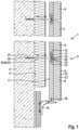
- the curtain wall 1 according to the invention shown in FIG. 1 comprises a building wall 2 and a facade cladding 3 arranged at a distance from the building wall 2 on the building wall 2.
- the building wall 2 is, for example, an exterior wall of a residential or other building.
- the facade cladding 3 is arranged in particular on or in front of an outer side 4 of the building wall 2, i.e., on the outside of, for example, the residential or other building.
- the long-shaft dowels 19 forming spacers 20 can generally also be regarded as fasteners for the facade cladding 3 of the curtain facade 1 according to the invention.
- the lowest panel 7 is arranged on one or more brackets 16, which are attached to the building wall 2 at equal heights and laterally spaced from one another in such a way that they hold the lowest panel 7 horizontally.
- the lowest panel 7 of the facade cladding 3 of the curtain wall 1 according to the invention is referred to here as the panel 7 under which no other panel 5, 6, 7 is located, in any case no panel 5, 6, 7 that is connected to a panel 5, 6, 7 arranged below it by a tongue 17 in the lower groove 12 in the lower edge 14 of the panel 7.
- the lowest panel 7 is also a lower panel 5.
- the panels 5, 6, 7 of the facade cladding 3 are supported on each other and, via the lowest panel 7, on the brackets 16.
- the bracket 16 has a height adjustment and a distance adjustment for the lowest panel 7 of the facade cladding 3 of the curtain facade 3 according to the invention.
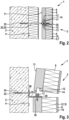
- Figure 2 shows a threaded rod 25 as an alternative to the long-shaft anchor 19.
- the threaded rod 25 is anchored with a mortar, adhesive, synthetic resin or the like in the anchor hole in the building wall 2 and penetrates the spring 17.
- nuts 26 are screwed onto the threaded rod 25 in such a way that the spring 17 and, via the spring 17, the panels 5, 6, 7 or the facade cladding 3 are held at their distance from the building wall 2.
- the threaded rod 25 forms the spacer 20 or, in general, the fastener that holds the panels 5, 6, 7 or the facade cladding 3 at their distance from the building wall 2.
- the thermal insulation layer 8 and the covering layer 9 of the upper panel 6 cover the threaded rod 25 forming the spacer 20 on the outer side 10.
- the brackets 16 are first attached to the building wall 2 and adjusted to the same height.
- the bottom panel 7 can be placed on the brackets 16. The bottom panel 7 is inserted with its lower groove 12 onto the L-profile strip 18 on the brackets 16, and the distance from the building wall 2 is adjusted.
- the expansion anchor 21 of the long-shaft anchor 19 is expanded by screwing an expansion screw (not visible in the drawing) into the anchor hole 22 in the building wall 2, thereby anchoring it in the building wall 2.
- the expansion screw can already be in the long-shaft anchor 19 while the distance is being adjusted, but not yet screwed deep enough into the expansion anchor 21 to cause it to expand.
- the expansion screw can also be inserted into the long-shaft anchor 19 only for expansion. If the spacer 20 is designed as a threaded rod 25, as described above, the distance is adjusted, or the set distance is fixed, using the nuts 26. Once the desired distance has been reached, the nuts 26 simply need to be counter-tightened against the spring 17.
- the other panels 5, 6 are placed one after the other, a tongue 17 is inserted into the upper groove 13 in each case and the distance from the building wall 2 is adjusted using long-shaft dowels 19 or threaded rods 25 and the panels 5, 6 are fastened to the building wall 2 at the adjusted distance.
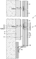
- the or an upper panel 6 is placed on the second leg 29 of the fastening angle 27 forming the spacer 20, projecting from the building wall 2, in such a way that the lower groove 12 is placed on the tongue 17, whereby the lower edge 14 of the upper panel 6 is arranged at the predetermined distance from the building wall 2.
- Figure 1 illustrated embodiment of the invention also extends to the third, in Figure 3 illustrated embodiment of the invention, the upper panel 6 of the facade cladding 3, the tongue 17 on the outer side 10 of the panels 5, 6, 7 or on the outer side 10 of the facade cladding 3.
- profiles 31 are screwed or otherwise fastened to the rear side 11 of the panels 5, 6, 7 facing the building wall 2, close to the upper and lower edges 14, 15 of the panels 5, 6.
- the profiles 31 can be strip-shaped and narrow in the longitudinal direction of the panels 5, 6, 7, and in this case, several profiles 31 are arranged at intervals next to one another on the rear side 11 of the panels 5, 6, 7.
- the profiles 31 can also be continuous in the longitudinal direction of the panels 5, 6, 7.
- the distance adjustment is also carried out in Figure 4 how to Figure 1 described by axial displacement of the long-shaft dowels 19 in the anchor holes 22 in the building wall 2, while the long-shaft dowels 19 or their expansion dowels 21 have not yet been expanded, and subsequent expansion of the expansion dowels 21 of the long-shaft dowels 19 in the anchor holes 22 in the building wall 2.
Landscapes
- Engineering & Computer Science (AREA)
- Architecture (AREA)
- Civil Engineering (AREA)
- Structural Engineering (AREA)
- Finishing Walls (AREA)
- Load-Bearing And Curtain Walls (AREA)
Applications Claiming Priority (2)
| Application Number | Priority Date | Filing Date | Title |
|---|---|---|---|
| DE102023127832 | 2023-10-12 | ||
| DE102024123974.3A DE102024123974A1 (de) | 2023-10-12 | 2024-08-22 | Vorgehängte Fassade |
Publications (2)
| Publication Number | Publication Date |
|---|---|
| EP4538478A2 true EP4538478A2 (fr) | 2025-04-16 |
| EP4538478A3 EP4538478A3 (fr) | 2025-06-18 |
Family
ID=92973600
Family Applications (1)
| Application Number | Title | Priority Date | Filing Date |
|---|---|---|---|
| EP24204083.0A Pending EP4538478A3 (fr) | 2023-10-12 | 2024-10-02 | Mur-rideau |
Country Status (1)
| Country | Link |
|---|---|
| EP (1) | EP4538478A3 (fr) |
Citations (2)
| Publication number | Priority date | Publication date | Assignee | Title |
|---|---|---|---|---|
| EP3329066B1 (fr) | 2015-07-27 | 2020-10-28 | Hamberger Industriewerke GmbH | Structure murale et procédé de montage |
| CN218714580U (zh) | 2021-10-29 | 2023-03-24 | 山东万事达建筑钢品股份有限公司 | 一种新型墙面夹芯板的企口构造 |
Family Cites Families (3)
| Publication number | Priority date | Publication date | Assignee | Title |
|---|---|---|---|---|
| AT8351U1 (de) * | 2005-05-24 | 2006-06-15 | Mayer Margit | Einrichtung zur befestigung von brettern |
| US20070151190A1 (en) * | 2005-12-19 | 2007-07-05 | Robert Huff | Thin stone or thin brick veneer wall system and clips therefor |
| KR101377248B1 (ko) * | 2012-03-19 | 2014-04-10 | 정일석건 주식회사 | 외벽 패널 고정구조 |
-
2024
- 2024-10-02 EP EP24204083.0A patent/EP4538478A3/fr active Pending
Patent Citations (2)
| Publication number | Priority date | Publication date | Assignee | Title |
|---|---|---|---|---|
| EP3329066B1 (fr) | 2015-07-27 | 2020-10-28 | Hamberger Industriewerke GmbH | Structure murale et procédé de montage |
| CN218714580U (zh) | 2021-10-29 | 2023-03-24 | 山东万事达建筑钢品股份有限公司 | 一种新型墙面夹芯板的企口构造 |
Also Published As
| Publication number | Publication date |
|---|---|
| EP4538478A3 (fr) | 2025-06-18 |
Similar Documents
| Publication | Publication Date | Title |
|---|---|---|
| EP2186966B1 (fr) | Structure de façades | |
| EP0921252B1 (fr) | Elément de fixation pour la fixation à distance de lattes, profilés, panneaux ou similaires sur un support fix | |
| EP2354368B1 (fr) | Etrier de fixation pour isolations murales | |
| EP0362718B1 (fr) | Barre de trame pour planchers surélevés | |
| DE2312663A1 (de) | Decken- oder wandverkleidung | |
| DE69832105T3 (de) | Wand einer Gebäudefassade | |
| EP3536873B1 (fr) | Élément profilé et système de façade comprenant un tel profilé | |
| EP2808143B1 (fr) | Coffrage destiné à la fabrication d'un escalier | |
| DE10307866B4 (de) | Glasfassade aus rahmenlos verlegten Glastafeln | |
| WO2015164987A1 (fr) | Structure de façade | |
| EP2281959A1 (fr) | Elément de connexion pour dalle en porte-à-faux | |
| EP4538478A2 (fr) | Mur-rideau | |
| DE102024123974A1 (de) | Vorgehängte Fassade | |
| DE9409626U1 (de) | Balkonkonstruktion | |
| EP1785546A1 (fr) | Console ancrable pour la fixation du revêtement d'un mur de bâtiment | |
| AT401788B (de) | Fassade | |
| EP1707699A2 (fr) | Façade de bâtiment ventilée et calorifugée | |
| DE19533551A1 (de) | Montagesystem für Platten | |
| EP3922784A1 (fr) | Dispositif de nivellement et de retrait | |
| AT413412B (de) | Wandelement | |
| EP2236692B1 (fr) | Système de revêtement de façades avec des panneaux des façades et des eléments de fixation comme aussi procédé de montage d' un système de revêtement de façades | |
| EP1589158A2 (fr) | Dispositif de fixation d'éléments de façade | |
| EP4379164A1 (fr) | Paroi extérieure d'un bâtiment avec une façade disposée devant celle-ci | |
| DE9210067U1 (de) | Vorrichtung zur Halterung plattenförmiger Fassadenelemente einer Gebäudeverkleidung | |
| DE29622444U1 (de) | Zaun |
Legal Events
| Date | Code | Title | Description |
|---|---|---|---|
| PUAI | Public reference made under article 153(3) epc to a published international application that has entered the european phase |
Free format text: ORIGINAL CODE: 0009012 |
|
| STAA | Information on the status of an ep patent application or granted ep patent |
Free format text: STATUS: THE APPLICATION HAS BEEN PUBLISHED |
|
| AK | Designated contracting states |
Kind code of ref document: A2 Designated state(s): AL AT BE BG CH CY CZ DE DK EE ES FI FR GB GR HR HU IE IS IT LI LT LU LV MC ME MK MT NL NO PL PT RO RS SE SI SK SM TR |
|
| PUAL | Search report despatched |
Free format text: ORIGINAL CODE: 0009013 |
|
| AK | Designated contracting states |
Kind code of ref document: A3 Designated state(s): AL AT BE BG CH CY CZ DE DK EE ES FI FR GB GR HR HU IE IS IT LI LT LU LV MC ME MK MT NL NO PL PT RO RS SE SI SK SM TR |
|
| RIC1 | Information provided on ipc code assigned before grant |
Ipc: E04F 13/08 20060101AFI20250509BHEP |
|
| STAA | Information on the status of an ep patent application or granted ep patent |
Free format text: STATUS: THE APPLICATION IS DEEMED TO BE WITHDRAWN |