EP4538493A1 - Kupplungselement für einen verschluss und ähnliche verschlüsse, die auf eine verwandte wickelrolle gewickelt werden können - Google Patents
Kupplungselement für einen verschluss und ähnliche verschlüsse, die auf eine verwandte wickelrolle gewickelt werden können Download PDFInfo
- Publication number
- EP4538493A1 EP4538493A1 EP23203116.1A EP23203116A EP4538493A1 EP 4538493 A1 EP4538493 A1 EP 4538493A1 EP 23203116 A EP23203116 A EP 23203116A EP 4538493 A1 EP4538493 A1 EP 4538493A1
- Authority
- EP
- European Patent Office
- Prior art keywords
- coupling
- winding roller
- coupling member
- main body
- windable
- Prior art date
- Legal status (The legal status is an assumption and is not a legal conclusion. Google has not performed a legal analysis and makes no representation as to the accuracy of the status listed.)
- Pending
Links
Images


Classifications
-
- E—FIXED CONSTRUCTIONS
- E06—DOORS, WINDOWS, SHUTTERS, OR ROLLER BLINDS IN GENERAL; LADDERS
- E06B—FIXED OR MOVABLE CLOSURES FOR OPENINGS IN BUILDINGS, VEHICLES, FENCES OR LIKE ENCLOSURES IN GENERAL, e.g. DOORS, WINDOWS, BLINDS, GATES
- E06B9/00—Screening or protective devices for wall or similar openings, with or without operating or securing mechanisms; Closures of similar construction
- E06B9/02—Shutters, movable grilles, or other safety closing devices, e.g. against burglary
- E06B9/08—Roll-type closures
- E06B9/11—Roller shutters
- E06B9/17—Parts or details of roller shutters, e.g. suspension devices, shutter boxes, wicket doors, ventilation openings
- E06B9/171—Rollers therefor; Fastening roller shutters to rollers
Definitions
- the present invention relates to the sector of windable closures, such as, for example, roller shutters, which are commonly also known as shutters, rolling gates, sun shades and similar closures.
- the invention has been developed with particular regard for a coupling member for the actual windable closure structure with respect to the related winding roller.
- Windable closures are commonly used to close doors and windows of buildings, shop windows, openings of garages and other openings of buildings.
- the windable closures which serve to close doors and windows in residential buildings are called roller shutters or more commonly shutters.
- the closures of shop fronts and garages are instead called rolling gates or less correctly shutters. They form part of windable closures, including windable shades, such as sun shades, and other similar closures.
- Windable closures have multiple applications and can be used, for example, as a means for controlling access to buildings, for example, in order to prevent intrusions or acts of vandalism. They can also be used as instruments for protection from atmospheric agents, such as rain, hail, wind, snow and are sometimes also used as protection from fires. Furthermore, windable closures can be used to adjust the brightness inside environments because it is possible to adjust the winding degree thereof and therefore to vary the opening extent of the relevant space, for example, the door or the window.
- a windable closure generally comprises a windable structure on a movement shaft which is also referred to as a winding roller and which can be rotated about an axis which is usually horizontal and normally positioned above the space affected by the windable closure.
- the windable structure may be a flexible web, as in the case of windable shades, or may be formed by horizontal elements which are articulated to each other, as in the case of roller shutters or rolling gates.
- the horizontal elements are slats which are also known as laths and which are parallel with and articulated to each other and made from various materials, for example, wood, metal or plastics material.
- the winding roller can be caused to rotate by means of a motor or manually so as to allow the winding and unwinding of the windable closure.
- the winding roller In order to manually actuate the winding roller, for example, there can be used a belt which is wrapped around a pulley which is mounted at one end of the winding roller and which is coaxial with the longitudinal axis thereof. Alternatively, it is possible to use a crank which is connected to a gear mechanism which controls the winding roller in terms of rotation. In the case of heavy windable closures, such as rolling gates, but also increasingly often for roller shutters in residential buildings, the winding roller is controlled by an electric motor with a manual or automatic control system.
- the winding roller normally used in modern shutters is generally a metal tube, which virtually always has an octagonal cross-section and which carries on at least one of the octagonal faces thereof a group of openings, for example, holes, slots and grooves, in which the coupling members of the shutter can be fixed.
- the position, dimensions and spacing of these openings on the winding roller is generally such as to be compatible with the different coupling members of the different manufacturers of shutters.
- the thickness of the metal tube may vary so as to provide adequate resistance in accordance with the uses: winding rollers which are subjected to greater loads, for example, for very wide or very long shutters, have a thickness greater than the winding rollers for lower loads, which have a smaller thickness and are therefore more economical.
- the coupling members connect the upper end of the windable structure of a windable closure to the actual winding roller.
- the coupling members have, at one end thereof, a shaped profile which forms a groove in which a corresponding profile which is formed in the upper slat of the shutter is engaged.
- some types of modern coupling members are provided with a connection lock which is blocked in the openings provided for this purpose in the winding roller.
- a coupling member of this known type is described in IT 102022000006995 by the same Applicant.
- a number of coupling members of the windable structure with respect to the winding roller are composed of mesh elements which are hinged with respect to each other along an axis parallel with the longitudinal axis of the winding roller. These coupling members are capable of being blocked when the shutter is completely unrolled, thereby ensuring a secure blocking function of the shutter which cannot be lifted from outside. Examples of coupling members for shutters of this type are described, in addition to the publication already cited IT 102022000006995 by the same Applicant, in EP 1728962 and EP 1726771 .
- the type of coupling member described in these last two documents of the prior art comprise a connection lock which is coupled to the winding roller by means of a hook and grooves which are suitably provided in the winding roller. The hook can be inserted in one of the grooves in the winding roller by lowering two flexible metal rods which are then blocked under two tabs which prevent them from being lifted.
- connection members which are in the form of a flexible tongue made of steel.
- the flexible tongue has a preferably grooved end, in which there is engaged, as in the case of the connection members indicated above, the upper slat of the shutter.
- the other end of the flexible tongue has two opposing teeth which project at the sides of the tongue and which are constructed at the end of two corresponding resilient appendixes.
- the appendixes can be compressed with the fingers, acting counter to the resilience thereof so as to temporarily move the two teeth together, placing one on the other, in order to introduce them inside a horizontal groove which is provided in the winding roller. By releasing the appendixes, they return resiliently into a position in which the two teeth which are moved apart from each other engage against the internal surface of the winding roller, blocking at that location the flexible tongue which thereby connects the shutter to the winding roller.
- An object of the present invention is to overcome the disadvantages of the prior art by providing a simple and economical system for connecting the windable structures of shutters and similar windable closures to the respective winding rollers.
- Another object of the invention is to provide coupling members of the windable structures with respect to winding rollers of the standard type, for example, but not only, octagonal winding rollers which are provided with openings and slots which are rectangular along the extent thereof.
- Another object of the invention is to provide coupling members for shutters and the like which are reliable and economical.
- Another object of the invention is to provide coupling members which are simple to install and replace without any need to remove the shutter from the guides thereof or the winding roller from the housing thereof.
- a coupling member for a shutter and similar windable closures which are intended to be wound on a related winding roller, comprises a main body with a coupling end, which is shaped so as to retain an end of a windable closure.
- the coupling end can be formed so as to be adapted to various types of windable closures, both of the standardized type and specific types of manufacturers of windable closures.
- the main body of the coupling member further comprises an end which is opposite the coupling end and which comprises a coupling appendix with respect to a winding roller, which is provided to have at least one rectangular coupling opening.
- the coupling appendix is shaped so as to comprise a coupling head which projects from a stem which is thinner than the coupling head.
- the coupling head defines at least two opposing teeth, or projections, which are generally wider, considering the spatial requirement from a projecting end of a tooth to the end of an opposite tooth, than the width of the rectangular coupling opening in the winding roller.
- the at least two teeth are narrower, still considering the spatial requirement from a projecting end of a tooth to the end of an opposite tooth, than the height of the rectangular opening in the winding roller. It is thereby possible to secure the member to the winding roller by introducing the teeth in the direction of the height of the rectangular opening and then rotating them substantially through 90° so that they remain blocked inside the rectangular opening.
- the main body of the coupling member may be elongate and flat so as to be able to readily construct the coupling appendix by forming two opposing teeth with a small thickness.
- the main body of the coupling member may be constructed so as to be torsionally flexible in a resilient manner so that it is possible to twist it in order to rotate the coupling appendix substantially through 90° with respect to a non-twisted position for coupling the coupling member to the winding roller, bringing it temporarily into a configuration for insertion inside the rectangular opening in the winding roller.
- the resilience of the main body allows the coupling member to automatically return into the non-twisted configuration.
- the main body of the coupling member may comprise a longitudinal portion which is formed with two parallel branches which are separated transversely from each other by a central slot which promotes the resilient torsion of the main body.
- the coupling end may be constructed so as to be integral with the main body and is also made from plastics material. This contributes to making the coupling member light and economical, an aspect which is very relevant if it is considered that normally at least two coupling members are necessary for each shutter of a building. The reduction of the unit cost of the coupling members therefore brings about a substantial reduction in the installation cost of all the shutters of a building.
- the coupling end of the coupling member may be made of metal rather than integrally from plastics material like the main body.
- the coupling end may be part of a metal insert which is fixed to the main body made of plastics material in accordance with various techniques, for example, by injection-moulding or other functionally equivalent systems.
- each coupling member is secured to an upper slat of the shutter or similar windable closure by means of the respective coupling end.
- the coupling appendix of each coupling member is coupled to the winding roller by securing the respective coupling head in a respective rectangular opening in the winding roller.
- any combination of any two features which are expressly described must be understood to be expressly described even if the features are extracted individually from the specific context in which they may be beside or combined with other different features, taking account of the competences and knowledge of a person skilled in the art in the sector who understands the possibility of functionally combining the features without it being necessary to functionally apply the other different features.
- each and any element, member, means, system, component, object which is described and illustrated in the present description has to be understood to be individually described and autonomously able to be modified and able to be separated from and/or combined with each and any other element, member, means, system, component, object which is described and illustrated.
- the materials, forms and functions which are described and illustrated do not limit the present invention but instead are only set out in order to allow a person skilled in the art to understand and carry out the invention according to preferred though non-exclusive embodiments.
- a first example of a coupling member 1 for windable closures is illustrated as a perspective view, for example, shutters and the like.
- the coupling member 1 is used to connect the windable structure of a windable closure, for example, the structure which is formed by the slats of a shutter (not visible in the Figures) to a winding roller 2 (illustrated in Figures 2 and 3 ).
- a winding roller 2 illustrated in Figures 2 and 3
- the coupling members 1 are mounted with spacing from each other so as to distribute the lifting force over the length of the upper slat of the shutter.
- the coupling member 1 comprises a main body 3 which is preferably flat and preferably elongate in a longitudinal direction X-X which widens transversely, with great radii 4, in order to define a coupling end 5 for the coupling to a shutter or other windable closure.
- the coupling end 5 is profiled so as to define a groove 6 with a coupling portion 7 which can retain in known manner the upper slat of a shutter.
- the form and the structure of the coupling end 5 can vary widely with respect to the one illustrated in Figure 1 in order to be adapted to different types of windable structures.
- the great radii 4 reduce the concentrations of forces in the transition zone from the body 3 towards the coupling end 5 thereof.
- the great width of the coupling end 5 allows the traction force which is applied during lifting via the coupling member 1 to be distributed over a greater surface of the upper slat of the shutter.
- the slot 8 defines on the main body 3 two branches 9 which are mutually parallel. At the end of the main body 3, opposite the coupling end 5, the two branches 9 join each other in a planar zone 10 which terminates with a coupling appendix 11.
- the coupling appendix 11 comprises a short stem 12 which projects from the body 3 and which is aligned with the middle X-X but slightly inclined with respect to the plane of the body 3.
- the stem 12 terminates with a coupling head 13 which is wider than it is thick.
- the end 14 of the coupling head 13 is rounded while the coupling head 13 widens to form two teeth 15 at the side adjacent to the stem 12.
- the overall width of the coupling head 13 in the region of the teeth 15 is approximately double the thickness of the coupling head 13.
- the dimensions of the coupling head 13 are determined on the basis of the dimensions of rectangular openings, which are generally standardized and which may be located in the winding rollers.
- the width of the coupling head 13 in the region of the teeth 15 is greater than 5 mm and less than 8 mm, therefore, for example, between 7 and 7.5 mm.
- the thickness of the coupling head 13 in this case is slightly less than 5 mm, for example, between 4 and 4.5 mm.
- the coupling member is made from a plastics material, for example, nylon or another polyamide. As a result of these dimensions, the coupling head 13 is much more solid than the resilient steel tongues of the coupling members of the prior art.
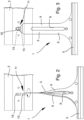
- the coupling member 1 is secured to the winding roller 2 by inserting the coupling head 13 into a rectangular opening 16 which is provided in the winding roller 2.
- Most of the winding rollers have rectangular openings with standardized dimensions, for example, 4 x 8 mm, with the long side of the rectangular opening being orientated transversely with respect to the axis of the winding roller 2.
- the body 3 In order to insert the coupling head 13 into the rectangular opening 16, the body 3 is twisted through 90°, regardless of whether this is in the clockwise or counter-clockwise direction, in such a manner that the coupling head 13 is present with the teeth 15 substantially aligned with the long side of the rectangular opening 16.
- the torsion of the body 3 is promoted by the formation thereof with the two branches 9 which are separated by the slot 8. It is thereby possible to insert the coupling head 13 in the rectangular opening 16 on the winding roller 2. Once the coupling head 13 is inside the winding roller 2, the torsion on the body 3 is released in such a manner that it returns resiliently into the non-deformed configuration, as illustrated in Figure 2 .
- the coupling head 13 rotates through 90° with respect to the direction in which it was introduced into the opening 16 so that the teeth 15 remain blocked by the short side of the rectangular opening 16.
- the coupling head 13 is thereby retained inside the winding roller 2 which thereby secures to itself the shutter which is coupled to the other coupling end 5 of the coupling member 1.
- Figure 4 illustrates as a perspective view a second example of a coupling member 10 which is similar to the coupling member 1 described above in terms of functionality and formation.
- Reference numerals identical to those of Figures 1 to 3 identify identical elements in the two exemplary embodiments.
- the coupling member 20 also comprises a main body 21 which is also preferably flat and preferably elongate in a longitudinal direction X-X which widens transversely in order to define a coupling end 5, the characteristics of which have already been described above with reference to the coupling member 1.
- a slot 22 which involves a good portion of the length of the body 3.
- the slot 22 defines on the main body 21 two branches 23 which are mutually parallel and which join each other in a junction area 24.
- Two appendixes 25 extend in continuation of the branches 23 towards the end of the body 21 in order to define a housing 26, which is U-shaped in the Figure and in which there is fixed a metal insert 27 which is flat and relatively flexible.
- connection between the body 21 and the metal insert 27 may be brought about mechanically, by injection-moulding the two elements in such a manner that the plastics material of the body 21 incorporates a portion of the metal insert 27 which can be provided for the purpose with corrugations or openings in the zone which is surrounded by the plastics material of the body 21 so as to promote the fixing of the two elements to each other.
- the body 21 may be connected to the metal insert 27 with other methods, for example, by means of bonding or with screws, rivets or other means of the type.
- the metal insert 27 terminates with a coupling appendix 28 which comprises a slot 29 from which a coupling head 30 projects.
- the end 31 of the coupling head 30 is rounded while at the side adjacent to the slot 29 the coupling head 30 widens substantially in steps to form two teeth 32.
- the coupling head 30 also has a total width, in the region of the teeth 32, which is greater than the width of the rectangular openings in the winding roller 2 but less than the height thereof.
- the width of the coupling head 30 in the region of the teeth 32 is greater than 5 mm and less than 8 mm, for example, between 7 and 7.5 mm.
- the thickness of the coupling head 30 is defined by the thickness of the metal insert 27 which in any case is less than the width of the rectangular opening and is typically a couple of millimetres.
- the coupling member 20 is secured to the winding roller 2 substantially in the same manner as described above with reference to the first embodiment of Figures 2 and 3 .
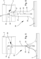
- the coupling head 30 is inserted into the rectangular opening 16 of the winding roller 2 by twisting the body 21 through 90°, irrespective of whether this is in the clockwise or counter-clockwise direction, as illustrated in Figure 5 , so that the coupling head 30 is present with the teeth 32 substantially aligned with the long side of the rectangular opening 16.
- the torsion of the body 21 is promoted by the formation thereof with the two branches 23 separated by the slot 22. It is thereby possible to insert the coupling head 30 into the rectangular opening 16 in the winding roller 2.
- the coupling head 30 is inside the winding roller 2, the torsion on the body 21 is released so that it returns resiliently into the non-deformed configuration, as illustrated in Figure 6 .
- the coupling head 20 rotates through 90° with respect to the direction in which it was introduced into the opening 16 so that the teeth 32 remain blocked by the short side of the rectangular opening 16.
- the coupling head 30 is thereby retained inside the winding roller 2 which thereby secures to itself the shutter which is coupled to the other coupling end 5 of the coupling member 20.
Landscapes
- Engineering & Computer Science (AREA)
- Structural Engineering (AREA)
- Architecture (AREA)
- Civil Engineering (AREA)
- Operating, Guiding And Securing Of Roll- Type Closing Members (AREA)
Priority Applications (1)
| Application Number | Priority Date | Filing Date | Title |
|---|---|---|---|
| EP23203116.1A EP4538493A1 (de) | 2023-10-12 | 2023-10-12 | Kupplungselement für einen verschluss und ähnliche verschlüsse, die auf eine verwandte wickelrolle gewickelt werden können |
Applications Claiming Priority (1)
| Application Number | Priority Date | Filing Date | Title |
|---|---|---|---|
| EP23203116.1A EP4538493A1 (de) | 2023-10-12 | 2023-10-12 | Kupplungselement für einen verschluss und ähnliche verschlüsse, die auf eine verwandte wickelrolle gewickelt werden können |
Publications (1)
| Publication Number | Publication Date |
|---|---|
| EP4538493A1 true EP4538493A1 (de) | 2025-04-16 |
Family
ID=89121575
Family Applications (1)
| Application Number | Title | Priority Date | Filing Date |
|---|---|---|---|
| EP23203116.1A Pending EP4538493A1 (de) | 2023-10-12 | 2023-10-12 | Kupplungselement für einen verschluss und ähnliche verschlüsse, die auf eine verwandte wickelrolle gewickelt werden können |
Country Status (1)
| Country | Link |
|---|---|
| EP (1) | EP4538493A1 (de) |
Citations (6)
| Publication number | Priority date | Publication date | Assignee | Title |
|---|---|---|---|---|
| DE7627375U1 (de) * | 1976-09-02 | 1978-02-23 | Fa. Ernst Selve, 5880 Luedenscheid | Anordnung zur loesbaren, beweglichen verbindung einer am obergurt eines rolladens angebrachten oese mit einer rolladenwelle |
| EP1167680A2 (de) * | 2000-06-27 | 2002-01-02 | Weru Ag | Aufhängefedern für Rolladenpanzer |
| EP1726771A1 (de) | 2005-05-17 | 2006-11-29 | Zurfluh Feller | Vorrichtung zur Befestigung eines Rollladenvorhangs und Rollladen mit einer derartigen Vorrichtung |
| DE102009038468A1 (de) * | 2008-10-17 | 2010-04-22 | Selve Gmbh & Co. Kg | Vorrichtung zur Verbindung eines Rollladenpanzers mit einer über einen Rollladengurt bzw. Rohrmotor angetriebenen Welle |
| EP3916190A1 (de) * | 2020-05-28 | 2021-12-01 | Gerhard Geiger GmbH & Co. KG | Federblockiersicherung |
| IT202200006995A1 (it) | 2022-04-07 | 2023-10-07 | Cs Plast S R L | Organo di aggancio per una tapparella e simili avvolgibili |
-
2023
- 2023-10-12 EP EP23203116.1A patent/EP4538493A1/de active Pending
Patent Citations (7)
| Publication number | Priority date | Publication date | Assignee | Title |
|---|---|---|---|---|
| DE7627375U1 (de) * | 1976-09-02 | 1978-02-23 | Fa. Ernst Selve, 5880 Luedenscheid | Anordnung zur loesbaren, beweglichen verbindung einer am obergurt eines rolladens angebrachten oese mit einer rolladenwelle |
| EP1167680A2 (de) * | 2000-06-27 | 2002-01-02 | Weru Ag | Aufhängefedern für Rolladenpanzer |
| EP1726771A1 (de) | 2005-05-17 | 2006-11-29 | Zurfluh Feller | Vorrichtung zur Befestigung eines Rollladenvorhangs und Rollladen mit einer derartigen Vorrichtung |
| EP1728962A2 (de) | 2005-05-17 | 2006-12-06 | Zurfluh Feller | Vorrichtung zur Befestigung eines Rollladenvorhangs und Rollladen mit einer derartigen Vorrichtung |
| DE102009038468A1 (de) * | 2008-10-17 | 2010-04-22 | Selve Gmbh & Co. Kg | Vorrichtung zur Verbindung eines Rollladenpanzers mit einer über einen Rollladengurt bzw. Rohrmotor angetriebenen Welle |
| EP3916190A1 (de) * | 2020-05-28 | 2021-12-01 | Gerhard Geiger GmbH & Co. KG | Federblockiersicherung |
| IT202200006995A1 (it) | 2022-04-07 | 2023-10-07 | Cs Plast S R L | Organo di aggancio per una tapparella e simili avvolgibili |
Similar Documents
| Publication | Publication Date | Title |
|---|---|---|
| US6068040A (en) | Slat edge retainer for overhead rolling doors | |
| US10422182B2 (en) | Unitized structural frame | |
| US20130048231A1 (en) | Base Slat Retention and Motor Triggering For Rolling Protective Shutters | |
| US6296039B1 (en) | Apparatus and method for windlocking a building opening | |
| US5595233A (en) | Hurricane shutters | |
| RU2378474C1 (ru) | Быстроходные промышленные жалюзийные ворота | |
| JP7108693B2 (ja) | 衝撃力を軽減するためのローラーシャッター | |
| EP1923533A2 (de) | Rolltor | |
| US20080141599A1 (en) | Deployment apparatus and system for flexible protective covering | |
| WO1997001015A1 (en) | Safety blind for windows and doors | |
| WO1999032749A2 (en) | Reinforced burglar- and storm-resistant cover for windows and doors | |
| EP2982827B1 (de) | Aufrollbare markise | |
| US20070006980A1 (en) | Roll up storm shutter slat connector retention system | |
| EP1728965A2 (de) | Jalousiesystem mit verbesserter selbstsperrender vorrichtung | |
| EP2407612B1 (de) | Verwendung einer Verwahrungsbox | |
| US20070012409A1 (en) | Rolling shutters | |
| EP4227481A1 (de) | Türmontage für eine doppeltür und zugehörige verriegelungsmethode | |
| KR930006476Y1 (ko) | 건물용 셔터 | |
| EP3312376A1 (de) | Rollladen | |
| US20080017329A1 (en) | Unitized Structural Frame | |
| JP3398849B2 (ja) | 建物用ドアにおけるワイヤ調節装置 | |
| EP2357311B1 (de) | Selbstschliessende lamelle für eine blende | |
| DE19600949A1 (de) | Rolladen für Fenster, Türen oder dergleichen | |
| EP4102014B1 (de) | Sicherheitsbegrenzer und montagewerkzeug für sicherheitsbegrenzer | |
| JP3418899B2 (ja) | 耐風フックを有するシャッタ−カ−テンの補強構造 |
Legal Events
| Date | Code | Title | Description |
|---|---|---|---|
| PUAI | Public reference made under article 153(3) epc to a published international application that has entered the european phase |
Free format text: ORIGINAL CODE: 0009012 |
|
| STAA | Information on the status of an ep patent application or granted ep patent |
Free format text: STATUS: THE APPLICATION HAS BEEN PUBLISHED |
|
| AK | Designated contracting states |
Kind code of ref document: A1 Designated state(s): AL AT BE BG CH CY CZ DE DK EE ES FI FR GB GR HR HU IE IS IT LI LT LU LV MC ME MK MT NL NO PL PT RO RS SE SI SK SM TR |
|
| STAA | Information on the status of an ep patent application or granted ep patent |
Free format text: STATUS: REQUEST FOR EXAMINATION WAS MADE |
|
| 17P | Request for examination filed |
Effective date: 20251015 |