EP4538557A2 - Frein à disque pour un véhicule automobile et agencement d'au moins un ressort de retenue de patin et d'un capot sur une garniture de frein - Google Patents
Frein à disque pour un véhicule automobile et agencement d'au moins un ressort de retenue de patin et d'un capot sur une garniture de frein Download PDFInfo
- Publication number
- EP4538557A2 EP4538557A2 EP25155832.6A EP25155832A EP4538557A2 EP 4538557 A2 EP4538557 A2 EP 4538557A2 EP 25155832 A EP25155832 A EP 25155832A EP 4538557 A2 EP4538557 A2 EP 4538557A2
- Authority
- EP
- European Patent Office
- Prior art keywords
- pad
- hood
- brake
- carrier plate
- retaining spring
- Prior art date
- Legal status (The legal status is an assumption and is not a legal conclusion. Google has not performed a legal analysis and makes no representation as to the accuracy of the status listed.)
- Pending
Links
Images






Classifications
-
- F—MECHANICAL ENGINEERING; LIGHTING; HEATING; WEAPONS; BLASTING
- F16—ENGINEERING ELEMENTS AND UNITS; GENERAL MEASURES FOR PRODUCING AND MAINTAINING EFFECTIVE FUNCTIONING OF MACHINES OR INSTALLATIONS; THERMAL INSULATION IN GENERAL
- F16D—COUPLINGS FOR TRANSMITTING ROTATION; CLUTCHES; BRAKES
- F16D55/00—Brakes with substantially-radial braking surfaces pressed together in axial direction, e.g. disc brakes
- F16D55/02—Brakes with substantially-radial braking surfaces pressed together in axial direction, e.g. disc brakes with axially-movable discs or pads pressed against axially-located rotating members
- F16D55/22—Brakes with substantially-radial braking surfaces pressed together in axial direction, e.g. disc brakes with axially-movable discs or pads pressed against axially-located rotating members by clamping an axially-located rotating disc between movable braking members, e.g. movable brake discs or brake pads
- F16D55/224—Brakes with substantially-radial braking surfaces pressed together in axial direction, e.g. disc brakes with axially-movable discs or pads pressed against axially-located rotating members by clamping an axially-located rotating disc between movable braking members, e.g. movable brake discs or brake pads with a common actuating member for the braking members
- F16D55/225—Brakes with substantially-radial braking surfaces pressed together in axial direction, e.g. disc brakes with axially-movable discs or pads pressed against axially-located rotating members by clamping an axially-located rotating disc between movable braking members, e.g. movable brake discs or brake pads with a common actuating member for the braking members the braking members being brake pads
- F16D55/226—Brakes with substantially-radial braking surfaces pressed together in axial direction, e.g. disc brakes with axially-movable discs or pads pressed against axially-located rotating members by clamping an axially-located rotating disc between movable braking members, e.g. movable brake discs or brake pads with a common actuating member for the braking members the braking members being brake pads in which the common actuating member is moved axially, e.g. floating caliper disc brakes
-
- F—MECHANICAL ENGINEERING; LIGHTING; HEATING; WEAPONS; BLASTING
- F16—ENGINEERING ELEMENTS AND UNITS; GENERAL MEASURES FOR PRODUCING AND MAINTAINING EFFECTIVE FUNCTIONING OF MACHINES OR INSTALLATIONS; THERMAL INSULATION IN GENERAL
- F16D—COUPLINGS FOR TRANSMITTING ROTATION; CLUTCHES; BRAKES
- F16D65/00—Parts or details
- F16D65/02—Braking members; Mounting thereof
- F16D65/04—Bands, shoes or pads; Pivots or supporting members therefor
- F16D65/092—Bands, shoes or pads; Pivots or supporting members therefor for axially-engaging brakes, e.g. disc brakes
- F16D65/095—Pivots or supporting members therefor
- F16D65/097—Resilient means interposed between pads and supporting members or other brake parts
- F16D65/0973—Resilient means interposed between pads and supporting members or other brake parts not subjected to brake forces
- F16D65/0974—Resilient means interposed between pads and supporting members or other brake parts not subjected to brake forces acting on or in the vicinity of the pad rim in a direction substantially transverse to the brake disc axis
- F16D65/0977—Springs made from sheet metal
- F16D65/0978—Springs made from sheet metal acting on one pad only
-
- F—MECHANICAL ENGINEERING; LIGHTING; HEATING; WEAPONS; BLASTING
- F16—ENGINEERING ELEMENTS AND UNITS; GENERAL MEASURES FOR PRODUCING AND MAINTAINING EFFECTIVE FUNCTIONING OF MACHINES OR INSTALLATIONS; THERMAL INSULATION IN GENERAL
- F16D—COUPLINGS FOR TRANSMITTING ROTATION; CLUTCHES; BRAKES
- F16D55/00—Brakes with substantially-radial braking surfaces pressed together in axial direction, e.g. disc brakes
- F16D2055/0004—Parts or details of disc brakes
- F16D2055/007—Pins holding the braking members
Definitions
- brake pads are held in so-called pad shafts of a pad carrier by a pad retaining bracket spanning a recess of a brake calliper and pressed against a bridge of the pad shaft by means of pad retaining springs.
- the pad retaining spring can, for example, be designed as an arc-shaped leaf spring.
- the hood is held in a holder of the lining carrier plate so that it can be deflected radially relative to the lining carrier plate and is pressed by the spring force of the lining retaining spring against an inner edge of the holder remote from the friction lining.
- the hood itself is designed as a stop against the lining carrier plate and thus prevents The pad retaining spring is clamped between the pad carrier plate and the pad retaining bracket.
- the cover as a separate, additional component of the disc brake, acts like a spacer and prevents the brake pad from hitting the pad retaining spring.
- the hood design described above allows, in particular, the pad retaining spring to be designed with a lower spring force, since extreme vibration loads do not have to be fully compensated by the pad retaining spring alone; instead, the hood serves as a supporting stop. The hood is thus exposed to the strong vibration loads instead of the pad retaining spring.
- the elasticity of the hood in the radial direction is smaller than the elasticity of the pad retaining spring and greater than the elasticity of the pad carrier plate and thus serves itself as a spring element with a greater spring constant than the pad retaining spring, so that hard impacts are cushioned by the hood itself and thereby protects and relieves the pad retaining spring.
- the receptacle is designed as a circumferentially closed through opening designed so that the hood is reliably held to the lining carrier plate.
- the pad backing plate is tapered in the axial direction to ensure sufficient clearance to adjacent brake components.
- adjacent edges of the hood are connected to one another in a material-to-material manner, in particular welded.
- a central part of the pad retaining spring has a slot through which a side wall of the hood is guided.
- top, bottom, left, right, front, rear, etc. refer exclusively to the exemplary representation and position of the brake pad, the brake lining, the pad retaining spring, the cover, and the like chosen in the respective figures. These terms are not to be understood as limiting; i.e., these references may change due to different operating positions or the mirror-symmetrical design, etc.
- Reference numeral 1 denotes a variant of a disc brake.
- the disc brake 1 has a brake disc 2 and a brake caliper 3 spanning the brake disc 2. which is designed here as a sliding saddle, with a clamping section 31 and a back section 32.
- a brake lever 17 is accommodated which can be actuated by a brake cylinder and which actuates a brake piston 16 which, when the brake is applied, presses against a brake pad 4 on the application side.
- the disc brake 1 has a rear brake pad 4.
- Each of the brake pads 4 has a pad carrier plate 41, which is held in the pad shaft 13 by a pad retaining spring 5 arranged on the pad carrier plate 41 against a pad retaining bracket 7 detachably attached to the brake caliper 3.
- a friction pad 42 is attached to the pad carrier plate 41, which is pressed against the friction surfaces of the brake disc 2 when the brake is applied.
- the pad retaining springs 5 are designed as arcuate leaf springs.
- the pad retaining springs 5 are mounted on a radially
- the axis of rotation of the brake disc 2 is held radially deflectable by the outer edge 43 of the pad carrier plate 41.
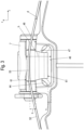
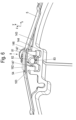
- a hood 6 covering the pad retaining spring 5 towards the pad retaining bracket 7 is, as shown in the Fig. 2 to 4 shown, mounted and held on the lining carrier plate 41 in the region of a receptacle 44 of the lining carrier plate 41 so as to be radially deflectable relative to the lining carrier plate 41.
- the hood 6 is preferably designed in the form of a clamp and can thus be spread open for installation in the receptacle 44 of the lining carrier plate 41.
- the hood 6 Due to the spring force of the pad retaining spring 5, which is supported in the area of outer pieces 51 on lugs 45 projecting radially outwards from the radially outer edge 43, the hood 6 is pressed against an underside 71 of the pad retaining bracket 7 facing the brake pad 4, so that during travel of the motor vehicle, for example on uneven roads, a movement of the brake pads 4 radially upwards, i.e. viewed from the axis of rotation of the brake disc 2 in the direction of the pad retaining bracket 7, is largely suppressed by the spring force of the pad retaining springs 5.
- the pad retaining spring 5 is freely movable in the radial direction within the hood 6, wherein the radial deflectability of the brake pad 4 is limited by the pad carrier plate 41 striking the hood 6 which is pressed by the pad retaining spring 5 onto the underside 71 of the pad retaining bracket 7 facing the brake pad 4.
- the distance a of a bottom side 61 of the hood 6 to a support surface 46 of the receptacle 44 of the pad carrier plate 41, against which the bottom side 61 of the hood 6 can be pressed in the event of a radial deflection of the brake pad 4 in the direction of the pad retaining bracket 7, is smaller than the distance b the pad retaining spring 5 to the radially outer edge of the pad carrier plate 41 in the area of the holder 44.
- the pad retaining springs 5 are held captively on the pad carrier plate 41 by means of the hood 6.
- the pad retaining spring 5 is formed with a slot 54 in the central region 53 of the pad retaining spring 5, through which, in the exemplary embodiment shown, the side wall 63 of the hood 6 near the friction lining 42 is passed, so that the pad retaining spring 5 is held on the hood 6 so as to be movable in the radial direction, but cannot be released from it when the hood 6 is fixed to the lining carrier plate 41.
- the receptacle 44 of the lining carrier plate 41 is preferably designed as a circumferentially closed through-opening.
- the receptacle 44 is, as shown in the Fig. 2-4 shown, is preferably slot-shaped and is delimited towards the pad retaining bracket 7 by a web 47.
- a bottom 61 of the hood 6 forming a base 61 is received in the slot.
- the receptacle 144 of the lining carrier plate 141 is delimited radially inwardly by two projections 147 directed toward one another in the direction of the longitudinal extension of the lining retaining spring 5.
- the projections 147 are enclosed by radially extending side walls 163 and a web formed on one of the side walls 163 and forming the underside 161 of the hood 106. Adjacent edges of the hood 6 are preferably connected to one another by a material bond, in particular welded to one another.
Landscapes
- Engineering & Computer Science (AREA)
- General Engineering & Computer Science (AREA)
- Mechanical Engineering (AREA)
- Braking Arrangements (AREA)
Applications Claiming Priority (3)
| Application Number | Priority Date | Filing Date | Title |
|---|---|---|---|
| DE102019128116.4A DE102019128116A1 (de) | 2019-10-17 | 2019-10-17 | Scheibenbremse für ein Kraftfahrzeug und Bremsbelag |
| EP20793346.6A EP4045808B1 (fr) | 2019-10-17 | 2020-10-16 | Frein à disque pour un véhicule automobile et agencement d'au moins un ressort de retenue de patin et d'un couvercle sur un patin de frein |
| PCT/EP2020/079240 WO2021074396A1 (fr) | 2019-10-17 | 2020-10-16 | Frein à disque pour un véhicule automobile et agencement d'au moins un ressort de retenue de patin et d'un couvercle sur un patin de frein |
Related Parent Applications (2)
| Application Number | Title | Priority Date | Filing Date |
|---|---|---|---|
| EP20793346.6A Division EP4045808B1 (fr) | 2019-10-17 | 2020-10-16 | Frein à disque pour un véhicule automobile et agencement d'au moins un ressort de retenue de patin et d'un couvercle sur un patin de frein |
| EP20793346.6A Division-Into EP4045808B1 (fr) | 2019-10-17 | 2020-10-16 | Frein à disque pour un véhicule automobile et agencement d'au moins un ressort de retenue de patin et d'un couvercle sur un patin de frein |
Publications (2)
| Publication Number | Publication Date |
|---|---|
| EP4538557A2 true EP4538557A2 (fr) | 2025-04-16 |
| EP4538557A3 EP4538557A3 (fr) | 2025-04-30 |
Family
ID=72944156
Family Applications (2)
| Application Number | Title | Priority Date | Filing Date |
|---|---|---|---|
| EP20793346.6A Active EP4045808B1 (fr) | 2019-10-17 | 2020-10-16 | Frein à disque pour un véhicule automobile et agencement d'au moins un ressort de retenue de patin et d'un couvercle sur un patin de frein |
| EP25155832.6A Pending EP4538557A3 (fr) | 2019-10-17 | 2020-10-16 | Frein à disque pour un véhicule automobile et agencement d'au moins un ressort de retenue de patin et d'un capot sur une garniture de frein |
Family Applications Before (1)
| Application Number | Title | Priority Date | Filing Date |
|---|---|---|---|
| EP20793346.6A Active EP4045808B1 (fr) | 2019-10-17 | 2020-10-16 | Frein à disque pour un véhicule automobile et agencement d'au moins un ressort de retenue de patin et d'un couvercle sur un patin de frein |
Country Status (9)
| Country | Link |
|---|---|
| EP (2) | EP4045808B1 (fr) |
| DE (1) | DE102019128116A1 (fr) |
| DK (1) | DK4045808T3 (fr) |
| ES (1) | ES3026434T3 (fr) |
| FI (1) | FI4045808T3 (fr) |
| HU (1) | HUE071697T2 (fr) |
| PL (1) | PL4045808T3 (fr) |
| PT (1) | PT4045808T (fr) |
| WO (1) | WO2021074396A1 (fr) |
Families Citing this family (1)
| Publication number | Priority date | Publication date | Assignee | Title |
|---|---|---|---|---|
| DE102021118770A1 (de) | 2021-07-20 | 2023-01-26 | Knorr-Bremse Systeme für Nutzfahrzeuge GmbH | Bremsbelaghalterung einer Scheibenbremse |
Family Cites Families (13)
| Publication number | Priority date | Publication date | Assignee | Title |
|---|---|---|---|---|
| DE102006034764A1 (de) * | 2005-12-14 | 2007-06-28 | Knorr-Bremse Systeme für Nutzfahrzeuge GmbH | Bremsbelag für eine Scheibenbremse |
| DE102007049981B4 (de) * | 2007-10-18 | 2009-07-30 | Knorr-Bremse Systeme für Nutzfahrzeuge GmbH | Bremsbelag einer Scheibenbremse |
| DE102008010570B3 (de) | 2008-02-22 | 2009-10-29 | Knorr-Bremse Systeme für Nutzfahrzeuge GmbH | Bremsbelag für eine Scheibenbremse |
| DE102012102584A1 (de) | 2012-03-26 | 2013-09-26 | Knorr-Bremse Systeme für Nutzfahrzeuge GmbH | Scheibenbremse mit Rückstelleinrichtung und Bremsbelag |
| DE102012108667A1 (de) | 2012-09-17 | 2014-03-20 | Knorr-Bremse Systeme für Nutzfahrzeuge GmbH | Anordnung eines Belaghaltebügels am Bremssattel einer Scheibenbremse sowie Bremsbelag |
| DE102014107227B4 (de) * | 2014-03-14 | 2016-02-04 | Knorr-Bremse Systeme für Nutzfahrzeuge GmbH | Scheibenbremse mit Belaghaltebügel und Sicherungsvorrichtung, und Bremsbelagsatz |
| DE202016102686U1 (de) | 2015-06-15 | 2016-06-23 | Knorr-Bremse Systeme für Nutzfahrzeuge GmbH | Scheibenbremse für ein Nutzfahrzeug und Bremsbelagsatz |
| DE102016104969A1 (de) | 2015-10-09 | 2017-04-13 | Knorr-Bremse Systeme für Nutzfahrzeuge GmbH | Scheibenbremse für ein Nutzfahrzeug |
| US10036437B2 (en) * | 2015-11-12 | 2018-07-31 | Bendix Spicer Foundation Brake Llc | Disc brake and set of brake pads |
| PT3458738T (pt) * | 2016-05-20 | 2023-02-07 | Knorr Bremse Systeme Fuer Nutzfahrzeuge Gmbh | Travão de disco para veículo comercial, pastilha de travão e conjunto de pastilhas de travão |
| DE102016117777B4 (de) * | 2016-09-21 | 2025-02-20 | Knorr-Bremse Systeme für Nutzfahrzeuge GmbH | Scheibenbremse für ein Nutzfahrzeug |
| DE102017113384B4 (de) * | 2017-06-19 | 2025-02-13 | Knorr-Bremse Systeme für Nutzfahrzeuge GmbH | Scheibenbremse mit einem Belaghaltesystem, und Bremsbelagsatz |
| DE102017129672B4 (de) | 2017-12-12 | 2025-05-08 | Knorr-Bremse Systeme für Nutzfahrzeuge GmbH | Scheibenbremse für ein Nutzfahrzeug und Bremsbelagsatz |
-
2019
- 2019-10-17 DE DE102019128116.4A patent/DE102019128116A1/de active Pending
-
2020
- 2020-10-16 FI FIEP20793346.6T patent/FI4045808T3/fi active
- 2020-10-16 EP EP20793346.6A patent/EP4045808B1/fr active Active
- 2020-10-16 DK DK20793346.6T patent/DK4045808T3/da active
- 2020-10-16 PT PT207933466T patent/PT4045808T/pt unknown
- 2020-10-16 PL PL20793346.6T patent/PL4045808T3/pl unknown
- 2020-10-16 WO PCT/EP2020/079240 patent/WO2021074396A1/fr not_active Ceased
- 2020-10-16 ES ES20793346T patent/ES3026434T3/es active Active
- 2020-10-16 EP EP25155832.6A patent/EP4538557A3/fr active Pending
- 2020-10-16 HU HUE20793346A patent/HUE071697T2/hu unknown
Also Published As
| Publication number | Publication date |
|---|---|
| ES3026434T3 (en) | 2025-06-11 |
| DK4045808T3 (da) | 2025-05-05 |
| WO2021074396A1 (fr) | 2021-04-22 |
| PL4045808T3 (pl) | 2025-08-18 |
| DE102019128116A1 (de) | 2021-04-22 |
| FI4045808T3 (fi) | 2025-05-20 |
| EP4045808A1 (fr) | 2022-08-24 |
| PT4045808T (pt) | 2025-05-05 |
| HUE071697T2 (hu) | 2025-09-28 |
| EP4538557A3 (fr) | 2025-04-30 |
| EP4045808B1 (fr) | 2025-04-02 |
Similar Documents
| Publication | Publication Date | Title |
|---|---|---|
| DE4126339C2 (de) | Schwimmsattel-Teilbelagscheibenbremse für Hochleistungsfahrzeuge | |
| EP2895764B1 (fr) | Agencement d'un étrier de support de garniture sur un étrier de frein à disque et garniture de frein | |
| EP2713074B1 (fr) | Garniture de frein pour un frein à disc | |
| DE102018114396B4 (de) | Scheibenbremse mit einer Rückstelleinrichtung und Bremsbelagsatz einer solchen Scheibenbremse | |
| DE102014112665B4 (de) | Bremsbelaghalterung einer Scheibenbremse, Scheibenbremse und Bremsbelag | |
| EP2895765B1 (fr) | Frein à disque pour véhicule | |
| EP2895760B1 (fr) | Frein à disque à commande pneumatique ou électromécanique | |
| EP3458737B1 (fr) | Frein à disque pour véhicule utilitaire et jeu de garnitures de frein | |
| WO2005119082A1 (fr) | Frein a disque pourvu d'un systeme elastique | |
| EP3033539B1 (fr) | Garniture de frein à disque et frein à disque | |
| EP4045808B1 (fr) | Frein à disque pour un véhicule automobile et agencement d'au moins un ressort de retenue de patin et d'un couvercle sur un patin de frein | |
| EP4163511A1 (fr) | Support de garniture de frein pour frein à disque de véhicule et garniture de frein pour véhicule | |
| EP1789695B1 (fr) | Frein a disque pour vehicule, notamment pour vehicule utilitaire | |
| EP3199827B1 (fr) | Frein à disque et serre-flan pour la fixation de garnitures de frein dans un frein à disque | |
| EP2083187A1 (fr) | Frein à disques pour un véhicule utilitaire et garniture de frein pour un frein à disques | |
| WO1992017713A1 (fr) | Frein a disque a garniture partielle et a etrier fixe | |
| WO1993003289A1 (fr) | Frein a disque a etrier flottant a agencement confortable des segments | |
| DE102014106090B4 (de) | Bremsbelaghalterung einer Scheibenbremse | |
| DE19650425B4 (de) | Bremsträger für eine Teilbelagscheibenbremse | |
| EP1977917A2 (fr) | Ensemble de palier pour pièces de véhicules, suspension de roue et procédé de fabrication d'un boîtier de palier pour l'ensemble de palier | |
| EP3199828B1 (fr) | Fixation de garniture de frein à disque de véhicule et serre-flan pour la fixation des garnitures de frein | |
| WO2021249884A1 (fr) | Plaquette de frein pour un frein à disque d'un véhicule et frein à disque | |
| EP0716246A1 (fr) | Jeu de patins pour frein à disque à étrier coulissant | |
| DE202008018282U1 (de) | Scheibenbremse für ein Nutzfahrzeug und Bremsbelag für eine Scheibenbremse | |
| EP0984187A2 (fr) | Support pour freins à tambour |
Legal Events
| Date | Code | Title | Description |
|---|---|---|---|
| PUAI | Public reference made under article 153(3) epc to a published international application that has entered the european phase |
Free format text: ORIGINAL CODE: 0009012 |
|
| STAA | Information on the status of an ep patent application or granted ep patent |
Free format text: STATUS: THE APPLICATION HAS BEEN PUBLISHED |
|
| REG | Reference to a national code |
Ref country code: DE Ref legal event code: R079 Free format text: PREVIOUS MAIN CLASS: F16D0065097000 Ipc: F16D0055226000 |
|
| PUAL | Search report despatched |
Free format text: ORIGINAL CODE: 0009013 |
|
| AC | Divisional application: reference to earlier application |
Ref document number: 4045808 Country of ref document: EP Kind code of ref document: P |
|
| AK | Designated contracting states |
Kind code of ref document: A2 Designated state(s): AL AT BE BG CH CY CZ DE DK EE ES FI FR GB GR HR HU IE IS IT LI LT LU LV MC MK MT NL NO PL PT RO RS SE SI SK SM TR |
|
| AK | Designated contracting states |
Kind code of ref document: A3 Designated state(s): AL AT BE BG CH CY CZ DE DK EE ES FI FR GB GR HR HU IE IS IT LI LT LU LV MC MK MT NL NO PL PT RO RS SE SI SK SM TR |
|
| RIC1 | Information provided on ipc code assigned before grant |
Ipc: F16D 65/097 20060101ALI20250327BHEP Ipc: F16D 55/226 20060101AFI20250327BHEP |
|
| STAA | Information on the status of an ep patent application or granted ep patent |
Free format text: STATUS: REQUEST FOR EXAMINATION WAS MADE |
|
| 17P | Request for examination filed |
Effective date: 20251030 |
|
| STAA | Information on the status of an ep patent application or granted ep patent |
Free format text: STATUS: EXAMINATION IS IN PROGRESS |
|
| RIC1 | Information provided on ipc code assigned before grant |
Ipc: F16D 55/226 20060101AFI20260224BHEP Ipc: F16D 65/097 20060101ALI20260224BHEP |
|
| 17Q | First examination report despatched |
Effective date: 20260320 |