EP4538574A1 - Dispositif d'accouplement - Google Patents
Dispositif d'accouplement Download PDFInfo
- Publication number
- EP4538574A1 EP4538574A1 EP23202867.0A EP23202867A EP4538574A1 EP 4538574 A1 EP4538574 A1 EP 4538574A1 EP 23202867 A EP23202867 A EP 23202867A EP 4538574 A1 EP4538574 A1 EP 4538574A1
- Authority
- EP
- European Patent Office
- Prior art keywords
- pipe
- tank
- external pipe
- coupling device
- washer
- Prior art date
- Legal status (The legal status is an assumption and is not a legal conclusion. Google has not performed a legal analysis and makes no representation as to the accuracy of the status listed.)
- Pending
Links
Images

Classifications
-
- F—MECHANICAL ENGINEERING; LIGHTING; HEATING; WEAPONS; BLASTING
- F16—ENGINEERING ELEMENTS AND UNITS; GENERAL MEASURES FOR PRODUCING AND MAINTAINING EFFECTIVE FUNCTIONING OF MACHINES OR INSTALLATIONS; THERMAL INSULATION IN GENERAL
- F16L—PIPES; JOINTS OR FITTINGS FOR PIPES; SUPPORTS FOR PIPES, CABLES OR PROTECTIVE TUBING; MEANS FOR THERMAL INSULATION IN GENERAL
- F16L25/00—Construction or details of pipe joints not provided for in, or of interest apart from, groups F16L13/00 - F16L23/00
- F16L25/02—Construction or details of pipe joints not provided for in, or of interest apart from, groups F16L13/00 - F16L23/00 specially adapted for electrically insulating the two pipe ends of the joint from each other
- F16L25/023—Construction or details of pipe joints not provided for in, or of interest apart from, groups F16L13/00 - F16L23/00 specially adapted for electrically insulating the two pipe ends of the joint from each other for joints in which sealing surfaces are pressed together by means of a member, e.g. a swivel nut, screwed on or into one of the joint parts
Definitions
- the invention relates to a coupling device for fluidically connecting a tank pipe of a tank to an external pipe. Also, the invention relates to a heating device for heating water comprising such a coupling device.
- a heating device like a heat pump is a device able to warm domestic water by transferring thermal energy to water by means of a heat exchanger.
- Water is hold and heated inside a tank and is supplied outside the tank by means of a pipe assembly.
- the pipes are usually made of metallic materials. However, the contact between two different metallic parts in presence with an electrolyte, such as water, provides galvanic corrosion which can result in a water leakage.
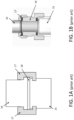
- FIG 1A A prior art configuration to connect two pipes of different materials, for example a steel pipe 15 and a copper pipe 16 is shown in figure 1A .
- a turning brass nut 17 is in contact with the steel pipe 15 and provides a galvanic torque, thereby generating corrosion.
- the use of a fiber gasket 18 which soak itself with electrolyte also provides a galvanic torque between the copper pipe 16, in particular its beaten collar, and the steel pipe 15, and produces therefore corrosion.
- two possible sources of corrosion can occur, one between the two pipes and the other between one pipe and the nut.
- a possible prior art solution to avoid said corrosion issues is illustrated in figure 1B .
- an additional dielectric fitting in plastic 19 can be placed between the steel pipe 15 and the copper pipe 16 for uncoupling the pipes of different materials.
- this solution can be achieved with additional costs.
- a coupling device for fluidically connecting a tank pipe of a tank to an external pipe, wherein the tank pipe is made of a first electrical conductive material and the external pipe is made of a second electrical conductive material, the first electrical conductive material being different from the second electrical conductive material, the coupling device comprising:
- the two hollow elements i.e. the two pipes
- a fluid e.g. a liquid as water
- the coupling device is placed at the connection region of the two hollow elements and is configured to allow the passage of the fluid from a hollow element to the other hollow element, by avoiding any possible leakage at the connection region.
- the tank pipe and the remaining part of the tank can be formed as a single part.
- the external pipe is not part of the tank and can be a part of a pipe system by means of which water is supplied for domestic use.
- the heating device can comprise a heat pump that is fluidically connected to the tank. Additionally, the heating device can be part of a heating system to supply water for domestic use.
- the coupling in particular dielectric connection arrangement, further comprises a gasket positionable between the two hollow elements to uncouple the tank pipe from the external pipe.
- uncouple means that two components do not contact each other. Specifically, the tank pipe and the external pipe do not contact each other due to the gasket.
- the gasket also serves to avoid a galvanic corrosion between the two hollow elements (i.e. the two pipes) that are made of two different conductive materials, i.e. two different metals. Since the gasket is a relative small element, it is not affecting the compactness of the entire arrangement.
- the gasket is compressed between the two hollow elements.
- the gasket is only compressed and there is no rotation of the gasket so that the risk of deterioration due to friction is eliminated.
- the gasket is made of an electrical insulating material, in particular of silicone.
- the material of the gasket can be selected to facilitate the positioning of the gasket between the two hollow elements and to improve the stability of the connection.
- the washer is made of plastic and the nut element is made of steel.
- the plastic can be selected of a particular hardness so as to increase the adaptability of the washer shape to the space between the nut and the external pipe, especially by screwing the nut.
- the tank pipe, in contact with the nut can also be made of steel.
- the washer comprises a washer collar.
- the washer collar serves to avoid any direct contact between the nut element and the external pipe in case the external pipe is provided itself with a collar element.
- the washer collar is made of an electrical insulating material, in particular of the same material of the washer, more in particular is made of plastic.
- the external pipe can be made of copper.
- a heating device for heating water comprises the tank, in particular water tank, having the tank pipe an external pipe being arranged outside the tank and an inventive coupling device.
- the coupling device is used to fluidically connect the tank pipe to the external pipe.
- the external pipe can comprise a collar element at one end, and the gasket of the coupling device is positioned between the tank pipe and the external pipe to uncouple the tank pipe from the external pipe, the collar element being placed between the gasket and the washer.
- the collar element serves to improve the closing action of the nut with the hollow elements.
- the washer is located between the nut element and the collar element to avoid any coupling between the main body and the nut element.
- the external pipe is bent, in particular comprises a curved elbow portion. In this way, the external pipe can be connected to the tank pipe even at locations where for example the space of the pipe assembly can be an issue.
- an inventive coupling device in particular dielectric coupling device, to fluidically connect a tank pipe to an external pipe of a heating device, in particular a heat pump water heater.
- the heating device can be part of a heating system to supply water for domestic use.
- FIG. 2 illustrates a coupling device 1, in particular a dielectric coupling device, applied to connect a tank pipe 2 to an external pipe 9.
- the two pipes 2, 9 are configured to allow the passage of a fluid, such as water, inside their cavities.
- One of the pipe, the external pipe 9, is provided with a collar element 12 at one end.
- the coupling device 1 serves to connect the tank pipe 2 to the external pipe 9 at a connection region at the collar element 12.
- the tank pipe 2 is made of steel, whereas the external pipe 9 is made of copper.
- the collar element 12 is therefore a beaten copper portion of the second pipe 3.
- the coupling device 1 comprises a fastener component such as nut element 4 that is used to make secure the connection of the two pipes and avoid any fluid leakage at the connection region.
- the nut element 4 is made of steel and in the fastening action it enters into contact with the tank pipe 2, also made of steel. Accordingly, the contact between the nut element 4 and the tank pipe 2 does not produce a galvanic corrosion since made of the same material.
- the washer 6 is made of plastic material, there is provided an electrical insulation between the nut element 4 and the external pipe. Accordingly, even if the external pipe 9 is made of a different material (i.e. different metal) compared to the nut element 4, no galvanic corrosion is produced. It is noted that the washer 6 is provided with a washer collar 21 (also made of plastic) to avoid any contact between the copper collar element 12 of the external pipe 9 and the nut element 4 during the fastening action. Thus, it is ensured that the nut element 4 and the external pipe 9 are not in contact with each other and thus uncoupled. The width of the washer collar 21 is such that the nut element 6 is prevented from touching the collar element 12 of the external pipe 9 when fastened.
- a gasket 5 made of silicon is placed between the tank pipe 2 and the external pipe 9.
- the gasket 5 is advantageously used to uncouple the steel pipe 2 from the copper pipe 9.
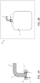
- FIGs 3A and 3B illustrate a coupling device 1 used to couple the tank pipe 11 to the external pipe 9 that is outside the tank 8.
- An example of tank 8, i.e. water tank, is schematically illustrated in figure 3B .
- the external pipe 9 differs from the external pipe 9 shown in figure 2 in that the external pipe is bent.
- the coupling device 1 serves to couple the external pipe 9, independent on whether the external pipe 9 is bended or not, to the tank pipe 11, thereby avoiding a galvanic corrosion between pipes of different materials.
- the tank pipe 11 is made of steel and the main body 10 is made of copper.
- the external pipe 9 is bent and comprises a curved elbow portion 14.
- the external pipe 8 can be a straight pipe as shown in figure 2 or can have other bent configurations, for example comprising more than one curved elbow portions 14.
Landscapes
- Engineering & Computer Science (AREA)
- General Engineering & Computer Science (AREA)
- Mechanical Engineering (AREA)
- Joints With Pressure Members (AREA)
Priority Applications (1)
| Application Number | Priority Date | Filing Date | Title |
|---|---|---|---|
| EP23202867.0A EP4538574A1 (fr) | 2023-10-11 | 2023-10-11 | Dispositif d'accouplement |
Applications Claiming Priority (1)
| Application Number | Priority Date | Filing Date | Title |
|---|---|---|---|
| EP23202867.0A EP4538574A1 (fr) | 2023-10-11 | 2023-10-11 | Dispositif d'accouplement |
Publications (1)
| Publication Number | Publication Date |
|---|---|
| EP4538574A1 true EP4538574A1 (fr) | 2025-04-16 |
Family
ID=88372162
Family Applications (1)
| Application Number | Title | Priority Date | Filing Date |
|---|---|---|---|
| EP23202867.0A Pending EP4538574A1 (fr) | 2023-10-11 | 2023-10-11 | Dispositif d'accouplement |
Country Status (1)
| Country | Link |
|---|---|
| EP (1) | EP4538574A1 (fr) |
Citations (6)
| Publication number | Priority date | Publication date | Assignee | Title |
|---|---|---|---|---|
| US2257385A (en) * | 1939-09-11 | 1941-09-30 | John G Keegan | Storage water heater |
| US2794658A (en) * | 1951-05-19 | 1957-06-04 | Roy C Purkhiser | Insulated pipe union with dip tube hanger |
| EP2891837A1 (fr) * | 2014-01-07 | 2015-07-08 | Atlantic Industrie | Procédé de fabrication de raccord tournant diélectrique et bimétallique et raccord tournant diélectrique et bimétallique correspondant |
| US9255656B2 (en) * | 2012-08-07 | 2016-02-09 | United States Thermoamp Inc. | Fitting for a heat pump and method of installation |
| US20200271256A1 (en) * | 2019-02-21 | 2020-08-27 | Legend Valve & Fitting, Inc. | Dielectric fitting |
| US20220186854A1 (en) * | 2020-12-10 | 2022-06-16 | Nibco Inc. | Dielectric union ball valve |
-
2023
- 2023-10-11 EP EP23202867.0A patent/EP4538574A1/fr active Pending
Patent Citations (6)
| Publication number | Priority date | Publication date | Assignee | Title |
|---|---|---|---|---|
| US2257385A (en) * | 1939-09-11 | 1941-09-30 | John G Keegan | Storage water heater |
| US2794658A (en) * | 1951-05-19 | 1957-06-04 | Roy C Purkhiser | Insulated pipe union with dip tube hanger |
| US9255656B2 (en) * | 2012-08-07 | 2016-02-09 | United States Thermoamp Inc. | Fitting for a heat pump and method of installation |
| EP2891837A1 (fr) * | 2014-01-07 | 2015-07-08 | Atlantic Industrie | Procédé de fabrication de raccord tournant diélectrique et bimétallique et raccord tournant diélectrique et bimétallique correspondant |
| US20200271256A1 (en) * | 2019-02-21 | 2020-08-27 | Legend Valve & Fitting, Inc. | Dielectric fitting |
| US20220186854A1 (en) * | 2020-12-10 | 2022-06-16 | Nibco Inc. | Dielectric union ball valve |
Similar Documents
| Publication | Publication Date | Title |
|---|---|---|
| CN103477138B (zh) | 电加热介质管及其制造方法 | |
| CN102612620B (zh) | 螺旋型柔性管连接器 | |
| US2794658A (en) | Insulated pipe union with dip tube hanger | |
| CN104071128A (zh) | 机动车辆风挡擦拭器风挡清洗液分配系统 | |
| EP4538574A1 (fr) | Dispositif d'accouplement | |
| US20020185867A1 (en) | Water heater connection system | |
| CN202229406U (zh) | 一种内置管式热交换器的防护结构 | |
| US20070259537A1 (en) | Coated microwave plug connector and cooking appliance with such a microwave plug connector | |
| WO2025001619A1 (fr) | Unité de module hydraulique et système de pompe à chaleur | |
| CN102331087B (zh) | 一种内置管式热交换器的防护结构 | |
| JP4124860B2 (ja) | ヘッダー | |
| JPH0249658Y2 (fr) | ||
| CN208638743U (zh) | 电加热器的电热管和接线盒安装结构 | |
| EP4686896A1 (fr) | Diélectrique en plastique combiné à un tuyau d'injection d'eau | |
| CN212746935U (zh) | 管路连接件、水路加热装置及燃气热水器 | |
| CN215595687U (zh) | 一种曲轴箱通风系统电加热接头装置 | |
| CN207350931U (zh) | 一种绝缘保护套及太阳能水管接头 | |
| CN107166732B (zh) | 一种进出水接头及热水器 | |
| CN223622504U (zh) | 一种管路加热装置及其转换接头 | |
| CN222916224U (zh) | 一种内置可伸缩电加热管的耐高压管道加热器 | |
| EP4253862A1 (fr) | Chauffe-eau | |
| CN111536349A (zh) | 一种不锈钢多通接头 | |
| CN215571300U (zh) | 一种电加热管组件、内胆及电热水器 | |
| CN222147134U (zh) | 一种新型的快插式电磁兼容接头 | |
| CN217583647U (zh) | 具有伴热和降温双功能的管道结构 |
Legal Events
| Date | Code | Title | Description |
|---|---|---|---|
| PUAI | Public reference made under article 153(3) epc to a published international application that has entered the european phase |
Free format text: ORIGINAL CODE: 0009012 |
|
| STAA | Information on the status of an ep patent application or granted ep patent |
Free format text: STATUS: THE APPLICATION HAS BEEN PUBLISHED |
|
| AK | Designated contracting states |
Kind code of ref document: A1 Designated state(s): AL AT BE BG CH CY CZ DE DK EE ES FI FR GB GR HR HU IE IS IT LI LT LU LV MC ME MK MT NL NO PL PT RO RS SE SI SK SM TR |
|
| STAA | Information on the status of an ep patent application or granted ep patent |
Free format text: STATUS: REQUEST FOR EXAMINATION WAS MADE |
|
| 17P | Request for examination filed |
Effective date: 20250514 |
|
| STAA | Information on the status of an ep patent application or granted ep patent |
Free format text: STATUS: EXAMINATION IS IN PROGRESS |