EP4538580A1 - Dispositif de sécurité et procédé de fonctionnement d'un dispositif de sécurité - Google Patents
Dispositif de sécurité et procédé de fonctionnement d'un dispositif de sécurité Download PDFInfo
- Publication number
- EP4538580A1 EP4538580A1 EP23203476.9A EP23203476A EP4538580A1 EP 4538580 A1 EP4538580 A1 EP 4538580A1 EP 23203476 A EP23203476 A EP 23203476A EP 4538580 A1 EP4538580 A1 EP 4538580A1
- Authority
- EP
- European Patent Office
- Prior art keywords
- sensor
- safety
- muting
- safety device
- image
- Prior art date
- Legal status (The legal status is an assumption and is not a legal conclusion. Google has not performed a legal analysis and makes no representation as to the accuracy of the status listed.)
- Pending
Links
Images


Classifications
-
- F—MECHANICAL ENGINEERING; LIGHTING; HEATING; WEAPONS; BLASTING
- F16—ENGINEERING ELEMENTS AND UNITS; GENERAL MEASURES FOR PRODUCING AND MAINTAINING EFFECTIVE FUNCTIONING OF MACHINES OR INSTALLATIONS; THERMAL INSULATION IN GENERAL
- F16P—SAFETY DEVICES IN GENERAL; SAFETY DEVICES FOR PRESSES
- F16P3/00—Safety devices acting in conjunction with the control or operation of a machine; Control arrangements requiring the simultaneous use of two or more parts of the body
- F16P3/12—Safety devices acting in conjunction with the control or operation of a machine; Control arrangements requiring the simultaneous use of two or more parts of the body with means, e.g. feelers, which in case of the presence of a body part of a person in or near the danger zone influence the control or operation of the machine
- F16P3/14—Safety devices acting in conjunction with the control or operation of a machine; Control arrangements requiring the simultaneous use of two or more parts of the body with means, e.g. feelers, which in case of the presence of a body part of a person in or near the danger zone influence the control or operation of the machine the means being photocells or other devices sensitive without mechanical contact
- F16P3/142—Safety devices acting in conjunction with the control or operation of a machine; Control arrangements requiring the simultaneous use of two or more parts of the body with means, e.g. feelers, which in case of the presence of a body part of a person in or near the danger zone influence the control or operation of the machine the means being photocells or other devices sensitive without mechanical contact using image capturing devices
-
- F—MECHANICAL ENGINEERING; LIGHTING; HEATING; WEAPONS; BLASTING
- F16—ENGINEERING ELEMENTS AND UNITS; GENERAL MEASURES FOR PRODUCING AND MAINTAINING EFFECTIVE FUNCTIONING OF MACHINES OR INSTALLATIONS; THERMAL INSULATION IN GENERAL
- F16P—SAFETY DEVICES IN GENERAL; SAFETY DEVICES FOR PRESSES
- F16P3/00—Safety devices acting in conjunction with the control or operation of a machine; Control arrangements requiring the simultaneous use of two or more parts of the body
- F16P3/12—Safety devices acting in conjunction with the control or operation of a machine; Control arrangements requiring the simultaneous use of two or more parts of the body with means, e.g. feelers, which in case of the presence of a body part of a person in or near the danger zone influence the control or operation of the machine
- F16P3/14—Safety devices acting in conjunction with the control or operation of a machine; Control arrangements requiring the simultaneous use of two or more parts of the body with means, e.g. feelers, which in case of the presence of a body part of a person in or near the danger zone influence the control or operation of the machine the means being photocells or other devices sensitive without mechanical contact
- F16P3/144—Safety devices acting in conjunction with the control or operation of a machine; Control arrangements requiring the simultaneous use of two or more parts of the body with means, e.g. feelers, which in case of the presence of a body part of a person in or near the danger zone influence the control or operation of the machine the means being photocells or other devices sensitive without mechanical contact using light grids
Definitions
- the invention relates to a safety device and a method for operating a safety device.
- muting mode when non-safety-critical objects pass through the monitoring area.
- the safety sensor In muting mode, the safety sensor is muted, i.e., bypassed, so that an object entering the monitoring area does not trigger the safety function. This allows non-safety-critical objects to pass through the monitoring area without unnecessarily shutting down the system.
- Muting sensors generally detect an object moving toward the monitoring area.
- a monitoring system that evaluates the muting sensors classifies the object based on the sensor signals. This means that a distinction is made as to whether it is a non-safety-critical object and thus a permissible object, or a safety-critical object, such as a person.
- the safety sensor Only if the object is classified as a permissible object is the safety sensor muted so that this permissible object can pass through the monitoring area without the safety sensor triggering the safety function.
- a disadvantage of the known safety device is that with the muting sensors a reliable distinction between safety-critical objects and non-safety-critical objects is not possible or only possible with a high degree of design effort.
- the invention is based on the object of providing a safe and reliable muting function for a safety device of the type mentioned at the outset with little design effort.
- the prerequisite for the safety sensor to operate in muting mode rather than normal operation is that the muting sensor detects an object approaching the monitoring area as a permissible object, i.e., as a non-safety-critical object.
- the safety sensor's muting mode is then temporarily maintained, ideally for as long as the permissible object needs to pass through the monitoring area.
- the safety sensor operates in normal mode if no permissible object is in the This means that any intrusion of the safety-critical object, especially persons, into the monitored area triggers the safety function. This ensures the reliable monitoring function of the safety device.
- the muting sensor of the safety device is designed in the form of an optical sensor, wherein the optical sensor has an image sensor as the receiver unit.
- the image sensor can be formed, for example, by a CMOS or CCD array.
- a transmitter unit emitting transmitted light beams is assigned to the receiver.
- received signals from the muting sensor are transmitted to the safety sensor, whereby a muting signal is generated in the safety sensor.
- Muting of the safety sensor can be initiated with the first muting signals. Muting of the safety sensor can be confirmed with the second muting signals. Muting can be ended by deactivating the signals.
- the determined distance or direction of movement lies within a specified target value range or corresponds to a specified limit value.
- the muting sensor generates fail-safe signals.
- the muting sensor advantageously has a multi-channel evaluation unit, wherein received signals from the or each image sensor are evaluated in the evaluation unit.
- the evaluation unit has two controller channels.
- the controller channels are designed in the form of a multi-core processor.
- the time interval between the signals is compared with a specified expectation, i.e., specified target values. This ensures fail-safe signal generation.
- safety sensor 4 During normal operation, safety sensor 4 generates a binary switching signal as an object detection signal.
- the switching states indicate whether or not an object has been detected by safety sensor 4 in the monitoring area. If safety sensor 4 detects an object in the monitoring area, the switching signal triggers a safety function. In this case, the switching signal activates a control system of system 3, transferring it to a safe state. In particular, system 3 is shut down.
- the safety sensor 4 can be operated in a muting mode in which the safety function is temporarily muted, i.e., silenced.
- the safety sensor 4 can also be designed in the form of another sensor, in particular in the form of an optical sensor.
- the safety sensor 4 can be designed as an area distance sensor, i.e., a scanning distance sensor. Like a light curtain, the area distance sensor monitors a flat monitoring area.
- the safety sensor 4 can be designed as a 3D camera, with distance measurements performed using a pulse-time-of-flight method. A three-dimensional spatial area is monitored with such a safety sensor 4. In this case, it is possible to monitor the entire danger zone 2 with the safety sensor 4.
- the watchdog controller can be formed by a computing core of the multi-core processor 18.
- the muting sensor 7 can also have two image sensors 13, which capture different images of objects, thereby obtaining diverse image information about the object. It is advantageous if these image sensors 13 are arranged offset to simultaneously capture different viewing angles or positions.
- the received signals from each image sensor 13 can be evaluated in one of the controller channels. Alternatively, the received signals from both image sensors 13 can be fed to both controller channels.
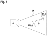
- the function of the muting sensor 7 is determined by Figure 5 explained.
- the muting sensor 7 is arranged in such a way that it detects the area in front of the monitoring area monitored by the safety sensor 4.
- contours themselves can also be determined in teach-in processes or specified as parameters.
- the criterion for determining whether an object is valid can be required, including that the distance and/or direction of movement lie within a specified target value range. Such parameters can also be determined during teach-in processes.
Landscapes
- Engineering & Computer Science (AREA)
- General Engineering & Computer Science (AREA)
- Mechanical Engineering (AREA)
- Geophysics And Detection Of Objects (AREA)
Priority Applications (1)
| Application Number | Priority Date | Filing Date | Title |
|---|---|---|---|
| EP23203476.9A EP4538580A1 (fr) | 2023-10-13 | 2023-10-13 | Dispositif de sécurité et procédé de fonctionnement d'un dispositif de sécurité |
Applications Claiming Priority (1)
| Application Number | Priority Date | Filing Date | Title |
|---|---|---|---|
| EP23203476.9A EP4538580A1 (fr) | 2023-10-13 | 2023-10-13 | Dispositif de sécurité et procédé de fonctionnement d'un dispositif de sécurité |
Publications (1)
| Publication Number | Publication Date |
|---|---|
| EP4538580A1 true EP4538580A1 (fr) | 2025-04-16 |
Family
ID=88412271
Family Applications (1)
| Application Number | Title | Priority Date | Filing Date |
|---|---|---|---|
| EP23203476.9A Pending EP4538580A1 (fr) | 2023-10-13 | 2023-10-13 | Dispositif de sécurité et procédé de fonctionnement d'un dispositif de sécurité |
Country Status (1)
| Country | Link |
|---|---|
| EP (1) | EP4538580A1 (fr) |
Citations (2)
| Publication number | Priority date | Publication date | Assignee | Title |
|---|---|---|---|---|
| EP1164556B1 (fr) * | 2000-05-26 | 2005-07-27 | Sick AG | Appareil d'alarme d'intrusion optoélectronique |
| EP2380709A2 (fr) * | 2010-04-22 | 2011-10-26 | Sick AG | Dispositif de sécurité 3D et procédé de sécurisation et de commande d'au moins une machine |
-
2023
- 2023-10-13 EP EP23203476.9A patent/EP4538580A1/fr active Pending
Patent Citations (2)
| Publication number | Priority date | Publication date | Assignee | Title |
|---|---|---|---|---|
| EP1164556B1 (fr) * | 2000-05-26 | 2005-07-27 | Sick AG | Appareil d'alarme d'intrusion optoélectronique |
| EP2380709A2 (fr) * | 2010-04-22 | 2011-10-26 | Sick AG | Dispositif de sécurité 3D et procédé de sécurisation et de commande d'au moins une machine |
Similar Documents
| Publication | Publication Date | Title |
|---|---|---|
| EP3011225B1 (fr) | Dispositif et procédé pour protéger une machine fonctionnant de manière automatisée | |
| DE102008004941B4 (de) | Sicherheitsanordnung und Verfahren | |
| DE102010036775A1 (de) | Entfernungsmessender optoelektronischer Sensor zur Montage an einer Durchgangsöffnung | |
| EP3415804B1 (fr) | Dispositif de sécurité | |
| EP3575666B1 (fr) | Dispositif de sécurisation d'une zone à risque d'une installation | |
| DE102009034848A1 (de) | Optoelektronischer Sensor | |
| DE102009048111A1 (de) | Sicherheitssensor | |
| EP3910230A1 (fr) | Dispositif de surveillance | |
| EP2888569B1 (fr) | Système de capteurs pour détecter un mouvement d'une source de lumière infrarouge | |
| DE10205691A1 (de) | Verfahren zum Überprüfen der Funktonssicherheit eines Bildsensors sowie Vorrichtung mit einem Bildsensor | |
| DE102009014574A1 (de) | Sicherheitssystem | |
| EP3150898B1 (fr) | Procede de commande automatisee d'un composant de machine | |
| EP1741299B1 (fr) | Dispositif et procede d'enregistrement d'une image | |
| DE202021104977U1 (de) | Überwachungseinrichtung | |
| EP1837586B1 (fr) | Dispositif de surveillance d'une zone dangereuse près d'une machine | |
| EP1826589B1 (fr) | Capteur optique destiné à la surveillance d'une zone de sécurité | |
| EP1738580B1 (fr) | Dispositif pour surveiller une zone, notamment pour securiser une zone dangereuse d'une installation automatique | |
| EP1873442A1 (fr) | Méthode et dispositif pour effectuer la surveillance de la sécurité d'un passage | |
| EP4538580A1 (fr) | Dispositif de sécurité et procédé de fonctionnement d'un dispositif de sécurité | |
| EP3855735B1 (fr) | Mise en sécurité d'une machine | |
| DE202022103201U1 (de) | Überwachungseinrichtung | |
| EP3875993B1 (fr) | Dispositif capteur et procédé de fonctionnement d'un dispositif capteur | |
| DE10128722C1 (de) | Vorrichtung zur Kontrolle von Objekten | |
| DE202022103234U1 (de) | Überwachungseinrichtung | |
| EP4531412B1 (fr) | Capture de flux d'objets à l'aide d'un capteur d'image basé sur des événements |
Legal Events
| Date | Code | Title | Description |
|---|---|---|---|
| PUAI | Public reference made under article 153(3) epc to a published international application that has entered the european phase |
Free format text: ORIGINAL CODE: 0009012 |
|
| STAA | Information on the status of an ep patent application or granted ep patent |
Free format text: STATUS: REQUEST FOR EXAMINATION WAS MADE |
|
| 17P | Request for examination filed |
Effective date: 20240508 |
|
| AK | Designated contracting states |
Kind code of ref document: A1 Designated state(s): AL AT BE BG CH CY CZ DE DK EE ES FI FR GB GR HR HU IE IS IT LI LT LU LV MC ME MK MT NL NO PL PT RO RS SE SI SK SM TR |
|
| P01 | Opt-out of the competence of the unified patent court (upc) registered |
Free format text: CASE NUMBER: APP_19332/2025 Effective date: 20250423 |