EP4538581A1 - Procédé de fonctionnement d'un purgeur de condensat et purgeur de condensat - Google Patents
Procédé de fonctionnement d'un purgeur de condensat et purgeur de condensat Download PDFInfo
- Publication number
- EP4538581A1 EP4538581A1 EP24193061.9A EP24193061A EP4538581A1 EP 4538581 A1 EP4538581 A1 EP 4538581A1 EP 24193061 A EP24193061 A EP 24193061A EP 4538581 A1 EP4538581 A1 EP 4538581A1
- Authority
- EP
- European Patent Office
- Prior art keywords
- condensate
- reservoir
- drain
- steam
- measuring sensor
- Prior art date
- Legal status (The legal status is an assumption and is not a legal conclusion. Google has not performed a legal analysis and makes no representation as to the accuracy of the status listed.)
- Pending
Links
Images




Classifications
-
- F—MECHANICAL ENGINEERING; LIGHTING; HEATING; WEAPONS; BLASTING
- F16—ENGINEERING ELEMENTS AND UNITS; GENERAL MEASURES FOR PRODUCING AND MAINTAINING EFFECTIVE FUNCTIONING OF MACHINES OR INSTALLATIONS; THERMAL INSULATION IN GENERAL
- F16T—STEAM TRAPS OR LIKE APPARATUS FOR DRAINING-OFF LIQUIDS FROM ENCLOSURES PREDOMINANTLY CONTAINING GASES OR VAPOURS
- F16T1/00—Steam traps or like apparatus for draining-off liquids from enclosures predominantly containing gases or vapours, e.g. gas lines, steam lines, containers
- F16T1/38—Component parts; Accessories
- F16T1/48—Monitoring arrangements for inspecting, e.g. flow of steam and steam condensate
Definitions
- the invention is therefore based on the object of designing the method of the type mentioned above in such a way that the amount of steam escaping from a steam consumer via a condensate drain can be determined in a reliable and technically simple manner. Furthermore, the invention is based on the object of providing a condensate drain for carrying out the method.
- a method for operating, in particular for controlling and/or regulating, a condensate drain.
- a fill level of a condensate that has accumulated and/or is accumulating in a condensate reservoir of the condensate drain for receiving condensate is monitored.
- the condensate is discharged when a level determined by at least one sensor is reached.
- a predetermined maximum fill level of the condensate in the condensate reservoir is fed to an outlet of the condensate drain during an emptying process of the condensate reservoir or during a feeding process via at least one condensate drain valve of the condensate drain arranged downstream of the reservoir.
- an equal amount in particular an equal volume and/or an equal mass of condensate, is always drained between the - rigidly defined - maximum fill level and a - rigidly defined - minimum fill level of the condensate in the reservoir of the condensate drain.
- This method for operating a steam trap offers significant advantages, particularly with regard to the reliable and technically simple determination of the quantity of steam escaping from a steam consumer, in particular the mass of steam, which is then discharged via the steam trap.
- Continuous monitoring of the fill level in the steam trap's condensate reservoir ensures that the quantity of steam escaping from the steam consumer and accumulating as condensate in the condensate reservoir can be accurately recorded.
- the draining process begins, with a precisely defined quantity of condensate being discharged between the maximum and minimum fill levels of the condensate reservoir.
- the method enables simple and consistent recording of the quantity of steam, without the need for complex measuring instruments, complicated calculations, or time-consuming calibration of the sensors used.
- the collected data on the amount of steam escaping as condensate from a steam consumer via the steam trap is also readily available and can be used to optimize steam operation and plan maintenance work.
- the method according to the invention contributes significantly to improving process control and efficiency, as it provides a reliable method for determining the amount of steam escaping, which is of great importance in many industrial applications.
- the discharged quantity is the volume of the condensate.
- a mass of the discharged condensate is determined based on this volume and/or at least a temperature of the condensate that influences the density of the condensate, in particular via a volume distribution, and is also recorded, in particular for each emptying process.
- the precise determination of the mass of the discharged condensate in particular taking into account the temperature-dependent density of the condensate, enables extremely accurate determination of the amount of energy discharged from a steam consumer. By taking the temperature dependence of the density into account, the measurement accuracy can be significantly improved, resulting in precise data on the amount of energy discharged.
- An increase in measurement accuracy can range from 10% to 15%, preferably 12% to 13%, and/or particularly preferably 12%.
- the measuring sensor and/or the additional measuring sensor would be designed as a temperature sensor.
- a more accurate determination of the amount of energy discharged enables more efficient use of energy sources, leading to cost savings.
- Precise energy quantity determination can further contribute to reducing the ecological footprint by minimizing unnecessary energy consumption.
- the collected data on the discharged condensate mass can be used for continuous monitoring and optimization of the system to ensure smooth operation and high performance. Overall, the precise determination of the discharged condensate mass and thus the amount of energy leads to a multitude of benefits, ranging from cost savings to improved environmental performance. This is particularly relevant in industrial applications where energy is a critical resource.
- the mass of steam discharged via the condensate trap is determined by the sum of the masses of condensate discharged during a respective emptying process. Due to the principle of conservation of mass, the mass of the discharged steam corresponds to the mass of the condensate discharged. Since the mass of the discharged steam corresponds to the mass of the condensate discharged, the calculation of the steam quantity is simple and direct. This considerably simplifies data acquisition and processing. This makes it advantageous to determine how much steam was removed from a steam consumer via the condensate trap during operation, and thus to draw conclusions about the associated energy costs. Through precise knowledge of the discharged Measures can be taken to make the operation of the steam consumer more efficient, especially if the amount of steam discharged is too high, which is particularly beneficial in industrial processes with high energy consumption.
- the definition and/or detection of the minimum fill level of the condensate in the condensate reservoir takes place in a time-controlled manner based on the maximum fill level.
- the minimum fill level in the condensate reservoir can be defined and/or detected based on the maximum fill level determined or measured by a measuring sensor by draining a defined volume of condensate from the condensate reservoir.
- the volume flow from the condensate reservoir is determined, in particular as a function of a differential pressure between the reservoir pressure prevailing in the condensate reservoir and the discharge pressure prevailing in the drain and/or the main line pressure prevailing in a condensate main line connected to the drain.
- the volume flow also depends on the geometry of the condensate reservoir and other components up to the drain of the condensate trap. Using the known volume flow from the condensate reservoir, a specific volume can be drained from the condensate reservoir over a defined period of time, thus setting the minimum fill level.
- the minimum fill level of the condensate in the condensate reservoir is defined and/or detected via the at least one, in particular first, measuring sensor and/or at least one further, in particular second, measuring sensor of the condensate drain.
- at least one measuring sensor particularly preferably exclusively one measuring sensor, is used to define and/or detect the maximum fill level and the minimum fill level, thus enabling cost-effective and precise measurement of the fill levels.
- the measuring sensors used to determine the maximum fill level and the minimum fill level can be those that are suitable for determining a fill level.
- the measuring sensors can thus be designed, for example, as ultrasonic sensors, capacitive sensors, pressure sensors, laser distance sensors, radar sensors, or the like.
- the sensors are designed as temperature sensors, for example, as a platinum measuring resistor such as a Pt100 temperature sensor.
- This advanced design also advantageously makes it possible to make a statement about the condition of the condensate drain, in particular the presence of any malfunctions.
- the, in particular first, measuring sensor and/or the further, in particular second, measuring sensor are designed as temperature sensors, in order to define and/or detect the maximum fill level and/or the minimum fill level of the condensate in the condensate reservoir
- the, in particular first, measuring sensor and/or the further, in particular second, measuring sensor can be arranged at least partially in an overall volume which comprises the condensate reservoir and/or volumes located outside the condensate reservoir and, in particular upstream or downstream, adjacent to the condensate reservoir, preferably directly, and/or connected to the condensate reservoir, and which are at least partially delimited.
- These volumes can be designed as at least one supply line and/or at least one discharge line of the condensate reservoir, wherein the supply line and/or discharge line can also comprise valves arranged in the flow path of the supply line and/or discharge line.
- the supply line or lines can in turn be designed as a condensate supply line and/or a steam supply line, and a discharge line can also be designed as a condensate discharge line.
- the total volume can furthermore be delimited by valves arranged upstream and/or downstream of the condensate reservoir, for example at least one steam valve, at least one condensate inlet valve and/or at least one condensate drain valve.
- the definition and/or detection of the maximum fill level and/or the minimum fill level of the condensate in the condensate reservoir takes place via a measurement by means of the, in particular, first, measuring sensor and/or by means of the further, in particular second, measuring sensor in a volume located outside the condensate reservoir and, in particular upstream and/or downstream and preferably directly, adjacent to the condensate reservoir and/or connected to the condensate reservoir, at least in sections.
- a respective volume can also comprise at least one valve, for example a condensate inlet valve and/or a steam valve.
- Such volumes are accordingly designed, in particular, as at least one supply line and/or at least one outlet of the condensate reservoir, wherein the supply line or supply lines can therefore be designed as at least one condensate supply line and/or at least one steam supply line.
- a outlet can also be designed as a condensate outlet.
- the maximum fill level is also defined and/or detected in at least one supply line of the condensate reservoir, in particular one that is upstream and/or directly adjacent to the condensate reservoir and/or connected to the condensate reservoir.
- the supply line or lines can, as already mentioned, be designed as a condensate supply line and/or a steam supply line.
- a measuring sensor, in particular designed as a temperature sensor, via which the maximum fill level is defined and/or detected, would accordingly be arranged at least partially in at least one of the supply lines and/or, if the total volume is delimited via valves, in a section of the supply line, i.e.
- an at least partially delimited volume can also be implemented as a supply line or discharge line, in particular a condensate supply line of the condensate reservoir and/or a condensate discharge line of the condensate buffer, wherein each volume can comprise at least one valve, for example a condensate inlet valve.
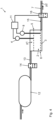
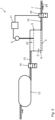
- the steam valve 9, the condensate inlet valve 14 and the condensate drain valve 16 are designed as shut-off valves with two switching positions: an open position and a shut-off position.
- the condensate drain 1 also has at least one measuring sensor 4, 8, via which a maximum fill level 5 and/or a minimum fill level 6 of the condensate 2 in the condensate reservoir 3 can be defined and/or detected.
- the at least one measuring sensor 4, 8 has a sensor arranged within the condensate reservoir 3.
- the described condensate drain 1 can also be seen in an arrangement in which the condensate drain 1 is arranged downstream of the steam consumer 17 or condensate generator and connected thereto. Furthermore, the main condensate line 18 connected to the condensate drain 1 is arranged downstream of the condensate drain 1.
- the condensate 2 is now fed to the drain 7 and thus to the main condensate line 18 in an emptying process of the condensate reservoir 3. This is done by moving the condensate inlet valve 14 into its closed position and the condensate drain valve 16 into its open position after detecting that the maximum filling level 5 has been reached, as shown in the Figure 2 During the emptying process, the steam from the steam consumer 17 continues to collect separated condensate 2 in the condensate buffer 12, since this cannot reach the condensate reservoir 3 due to the condensate inlet valve 14 being in its closed position.
- FIGS 2 to 4 show the condensate drain 1 during an emptying process, so that the condensate inlet valve 14 is in its closed position and the condensate drain valve 16 is in its open position.
- the reservoir pressure p1 is increased above the outlet pressure p2 and thus also the main line pressure p3 by switching on the steam line 10 connected to the condensate reservoir 3 via the steam valve 9.
- the definition and/or recording of the minimum level 6 differs when executing the Figures 1 and 2 However, compared to the execution of the Figure 3 .
- the condensate drain 1 has two measuring sensors 4, 8, wherein the maximum filling level 5 is defined and/or recorded via the first measuring sensor 4 and the minimum filling level 6 is defined and/or recorded via the further, second measuring sensor 8.
- a version with two sensors 4, 8, as in the version of the condensate drain 1 of the Figures 1 and 2 offers the advantage that a malfunction of the condensate drain 1, in particular a malfunction of the flow through the condensate drain 1, specifically towards the outlet 7 of the condensate drain 1, can be determined.
- an actual duration for an emptying process is recorded during an emptying process and compared with a target duration for the emptying process, whereby a deviation of the actual duration from the target duration for the emptying process determines a malfunction of the condensate drain 1.
- a tapering of line cross-sections occurs if the actual duration is longer than the target duration of the emptying process.
- the condensate drain 1 again has only one measuring sensor 4 for defining and/or detecting the maximum fill level 5 of the condensate 2 in the condensate reservoir 3.
- the definition and/or detection of the minimum fill level 6 of the condensate 2 in the condensate reservoir 3 is thus again carried out in a time-controlled manner based on the maximum fill level 5.
- the respective condensate drain 1 has the evaluation unit 11 for the purpose of monitoring emptying processes of the condensate reservoir 3 and for determining the mass of steam discharged via the condensate drain 1.
- This unit is also configured to determine the actual duration of an emptying process of the condensate reservoir 3 and to compare the actual duration with the target duration of the emptying process.
- the - first - sensor 4 as well as the one in the Figure 7 indicated further, second, measuring sensors 8 can basically be arranged in the total volume, which comprises the condensate reservoir 3 and/or outside the condensate reservoir 3 and directly adjacent to the condensate reservoir 3 upstream or downstream and/or connected to the condensate reservoir 3, at least partially delimited volumes.
- These adjacent volumes are in the embodiments of the Figures 6 to 8 the supply lines and the discharge line of the condensate reservoir 3, ie the condensate supply line 13 and/or the steam supply line 10 and the condensate discharge line 15, each comprising the condensate inlet valve 14, the steam valve 9 and the condensate drain valve 16.
- the resulting total volume is in the embodiments of the Figures 7 and 8 by the condensate inlet valve 14 and the condensate drain valve 16 and in the design of the Figure 6 by the condensate inlet valve 14, the steam valve 9 and the condensate drain valve 16.
- the - first - measuring sensor 4 and its connection to the evaluation unit 11 are shown in dashed form, wherein the - first - measuring sensor 4 is arranged at least partially in the steam supply line 10, which, directly adjacent to the condensate reservoir 3, arranged upstream of the condensate reservoir 3 and connected to the condensate reservoir 3.
- the respective measuring sensors 4 are in particular arranged at least partially in the section of the condensate inlet line 13 or the steam line 9 which is located between the condensate inlet valve 14 or the steam valve 9, in this case therefore downstream of the condensate inlet valve 14 or the steam valve 9, and the condensate reservoir 3.
- the - first - measuring sensor 4 is not arranged in this overall volume due to the delimitation of the overall volume by the condensate inlet valve 14, the steam valve 9 and the condensate drain valve 16.
- the - first - measuring sensor 4 is arranged in the section of the volume adjacent to the condensate buffer 12 and connected to the condensate buffer, and at least partially delimited, which volume is arranged between the condensate buffer 12 and the condensate inlet valve 14, i.e. upstream of the condensate inlet valve 14.
- This section is the section of the condensate supply line 13 between the condensate buffer 12 and the condensate inlet valve 14.
- the sensor 4 is arranged at least partially in the condensate buffer 12 of the condensate drain 1, which in this embodiment is designed as a tank.
- the condensate buffer 12 of the condensate drain 1 which in this embodiment is designed as a tank.
- Condensate drain valve 2 condensate 17
- Steam consumers 3
- Condensate reservoir 18 Condensate main line 4
- Sensor p1 Reservoir pressure 5
- Maximum fill level p2 Drain pressure 6
- Sequence 8 Sensor 9 steam valve 10 steam line 11 Evaluation unit 12
- Condensate buffer 13 Condensate supply line 14
- Condensate inlet valve 15 Condensate drainage
Landscapes
- Engineering & Computer Science (AREA)
- General Engineering & Computer Science (AREA)
- Mechanical Engineering (AREA)
- Pipeline Systems (AREA)
Applications Claiming Priority (1)
| Application Number | Priority Date | Filing Date | Title |
|---|---|---|---|
| DE102023127822.3A DE102023127822B3 (de) | 2023-10-11 | 2023-10-11 | Verfahren zum Betrieb eines Kondensatableiters sowie Kondensatableiter |
Publications (1)
| Publication Number | Publication Date |
|---|---|
| EP4538581A1 true EP4538581A1 (fr) | 2025-04-16 |
Family
ID=92258687
Family Applications (1)
| Application Number | Title | Priority Date | Filing Date |
|---|---|---|---|
| EP24193061.9A Pending EP4538581A1 (fr) | 2023-10-11 | 2024-08-06 | Procédé de fonctionnement d'un purgeur de condensat et purgeur de condensat |
Country Status (2)
| Country | Link |
|---|---|
| EP (1) | EP4538581A1 (fr) |
| DE (1) | DE102023127822B3 (fr) |
Cited By (1)
| Publication number | Priority date | Publication date | Assignee | Title |
|---|---|---|---|---|
| CN121008501A (zh) * | 2025-10-27 | 2025-11-25 | 四川星环纪元科技发展有限公司 | 一种压缩空气系统电子排凝的双延迟自整定排放控制方法 |
Citations (5)
| Publication number | Priority date | Publication date | Assignee | Title |
|---|---|---|---|---|
| DE2414671A1 (de) | 1974-03-27 | 1975-10-16 | Continental Gummi Werke Ag | Kondensatableiter fuer dampfverbraucher |
| EP0081826A2 (fr) * | 1981-12-16 | 1983-06-22 | Koch, Berthold | Dispositif pour purger des condensats et similaires hors de systèmes sous pression |
| DE29621722U1 (de) * | 1996-12-13 | 1997-03-27 | IER Meß- und Regeltechnik Eberhard Henkel GmbH, 68199 Mannheim | Überfüllsicherung für in Behälter einzufüllende, Flüssigkeiten, vorzugsweise für wassergefährdende Flüssigkeiten |
| DE19642704A1 (de) | 1996-10-16 | 1998-04-30 | Werner Wille | Kondensatableiter |
| DE102011053411A1 (de) | 2011-09-08 | 2013-03-14 | Beko Technologies Gmbh | Kondensatableiter mit Störungsüberwachung |
Family Cites Families (2)
| Publication number | Priority date | Publication date | Assignee | Title |
|---|---|---|---|---|
| DE4320395C2 (de) | 1993-06-19 | 1995-06-22 | Baelz & Sohn Gmbh & Co W | Kondensatableiter für ein Fernwärmesystem |
| US10641412B2 (en) | 2012-09-28 | 2020-05-05 | Rosemount Inc. | Steam trap monitor with diagnostics |
-
2023
- 2023-10-11 DE DE102023127822.3A patent/DE102023127822B3/de active Active
-
2024
- 2024-08-06 EP EP24193061.9A patent/EP4538581A1/fr active Pending
Patent Citations (5)
| Publication number | Priority date | Publication date | Assignee | Title |
|---|---|---|---|---|
| DE2414671A1 (de) | 1974-03-27 | 1975-10-16 | Continental Gummi Werke Ag | Kondensatableiter fuer dampfverbraucher |
| EP0081826A2 (fr) * | 1981-12-16 | 1983-06-22 | Koch, Berthold | Dispositif pour purger des condensats et similaires hors de systèmes sous pression |
| DE19642704A1 (de) | 1996-10-16 | 1998-04-30 | Werner Wille | Kondensatableiter |
| DE29621722U1 (de) * | 1996-12-13 | 1997-03-27 | IER Meß- und Regeltechnik Eberhard Henkel GmbH, 68199 Mannheim | Überfüllsicherung für in Behälter einzufüllende, Flüssigkeiten, vorzugsweise für wassergefährdende Flüssigkeiten |
| DE102011053411A1 (de) | 2011-09-08 | 2013-03-14 | Beko Technologies Gmbh | Kondensatableiter mit Störungsüberwachung |
Cited By (1)
| Publication number | Priority date | Publication date | Assignee | Title |
|---|---|---|---|---|
| CN121008501A (zh) * | 2025-10-27 | 2025-11-25 | 四川星环纪元科技发展有限公司 | 一种压缩空气系统电子排凝的双延迟自整定排放控制方法 |
Also Published As
| Publication number | Publication date |
|---|---|
| DE102023127822B3 (de) | 2025-03-27 |
Similar Documents
| Publication | Publication Date | Title |
|---|---|---|
| EP2191182B1 (fr) | Système diagnostique et procédé de diagnostic pour une soupape, en particulier une soupape de fermeture ou une soupape de réglage | |
| EP2698570B1 (fr) | Procédé de quantification d'un débit de fuite sur un appareil de réglage | |
| DE102011115244A1 (de) | Verfahren und System zur Überwachung des Betriebszustands einer Pumpe | |
| EP4538581A1 (fr) | Procédé de fonctionnement d'un purgeur de condensat et purgeur de condensat | |
| DE102011053411B4 (de) | Kondensatableiter mit Störungsüberwachung | |
| DE10247167A1 (de) | Dichtprüfeinrichtung und Verfahren zur Dichtheitsprüfung | |
| EP2805042A1 (fr) | Dispositif pour détecter l'usure par abrasion | |
| EP2725312B1 (fr) | Procédé et dispositif destinés à la surveillance d'une quantité de remplissage de produit réfrigérant | |
| EP2987996B1 (fr) | Robinet de vidange | |
| EP0676682A2 (fr) | Capteur solaire avec surveillance de panne | |
| EP0631218A2 (fr) | Système de chauffage à distance | |
| AT520464B1 (de) | Maschinenelement | |
| DE10135448B4 (de) | Vorrichtung zur Erfassung von Fluidverunreinigungen | |
| DE112021001297B4 (de) | Einrichtung zur überwachung einer abflussentfernung | |
| DE102020214001B4 (de) | Verfahren zum Betreiben eines Injektors an einer Brennkraftmaschine, Steuergerät für eine Brennkraftmaschine, eingerichtet zur Durchführung eines solchen Verfahrens, und Brennkraftmaschine mit einem solchen Steuergerät | |
| DE102015000080A1 (de) | Verschmutzungserkennung für Rohrleitungen | |
| DE102020204488B4 (de) | Verfahren und Auswertesystem zum Bestimmen eines Filterverschmutzungszustands, sowie Filtersystem und Maschine | |
| EP3640758B1 (fr) | Système de diagnostic et procédé pour dispositifs de mise en température | |
| DE102008034349B4 (de) | Leitungsvorrichtung mit einem optischen Partikelzähler zur Verunreinigungsüberwachung und Verfahren dafür | |
| EP4584826B1 (fr) | Procédé de detection d'un court-circuit dans un système de pile à combustible et système de pile à combustible | |
| DE10329909A1 (de) | System und Verfahren zur Bestimmung, Überwachung und Regulierung von Flüssigkeitsverlusten in Wasserversorgungsbetrieben oder Wasserversorgungsnetzen | |
| EP2837924B1 (fr) | Installation à huile caloporteuse équipée d'une détection de fuites, ainsi que procédé de détection de fuites sur une installation à huile caloporteuse | |
| DE102024109402A1 (de) | System und Verfahren zur Überwachung eines Kondensatabscheiders | |
| WO2023227263A1 (fr) | Procédé de surveillance d'une fuite de tambour sur un séparateur centrifuge | |
| DE102024129338A1 (de) | Verfahren zum Überwachen eines Betriebszustands eines Durchlauferhitzers, Verfahren zur Überwachung eines Betriebszustands eines Heizungssystems, Durchlauferhitzer, Heizungssystem und Computerprogrammprodukt |
Legal Events
| Date | Code | Title | Description |
|---|---|---|---|
| PUAI | Public reference made under article 153(3) epc to a published international application that has entered the european phase |
Free format text: ORIGINAL CODE: 0009012 |
|
| STAA | Information on the status of an ep patent application or granted ep patent |
Free format text: STATUS: THE APPLICATION HAS BEEN PUBLISHED |
|
| AK | Designated contracting states |
Kind code of ref document: A1 Designated state(s): AL AT BE BG CH CY CZ DE DK EE ES FI FR GB GR HR HU IE IS IT LI LT LU LV MC ME MK MT NL NO PL PT RO RS SE SI SK SM TR |
|
| STAA | Information on the status of an ep patent application or granted ep patent |
Free format text: STATUS: REQUEST FOR EXAMINATION WAS MADE |
|
| 17P | Request for examination filed |
Effective date: 20251015 |