EP4538587A2 - Ouverture de pression différentielle et soupape de fermeture d'un écoulement en excès pour bouteille à gaz - Google Patents
Ouverture de pression différentielle et soupape de fermeture d'un écoulement en excès pour bouteille à gaz Download PDFInfo
- Publication number
- EP4538587A2 EP4538587A2 EP25160450.0A EP25160450A EP4538587A2 EP 4538587 A2 EP4538587 A2 EP 4538587A2 EP 25160450 A EP25160450 A EP 25160450A EP 4538587 A2 EP4538587 A2 EP 4538587A2
- Authority
- EP
- European Patent Office
- Prior art keywords
- closing element
- main
- pilot
- seat
- main closing
- Prior art date
- Legal status (The legal status is an assumption and is not a legal conclusion. Google has not performed a legal analysis and makes no representation as to the accuracy of the status listed.)
- Pending
Links
Images


Classifications
-
- F—MECHANICAL ENGINEERING; LIGHTING; HEATING; WEAPONS; BLASTING
- F17—STORING OR DISTRIBUTING GASES OR LIQUIDS
- F17C—VESSELS FOR CONTAINING OR STORING COMPRESSED, LIQUEFIED OR SOLIDIFIED GASES; FIXED-CAPACITY GAS-HOLDERS; FILLING VESSELS WITH, OR DISCHARGING FROM VESSELS, COMPRESSED, LIQUEFIED, OR SOLIDIFIED GASES
- F17C13/00—Details of vessels or of the filling or discharging of vessels
- F17C13/04—Arrangement or mounting of valves
-
- F—MECHANICAL ENGINEERING; LIGHTING; HEATING; WEAPONS; BLASTING
- F16—ENGINEERING ELEMENTS AND UNITS; GENERAL MEASURES FOR PRODUCING AND MAINTAINING EFFECTIVE FUNCTIONING OF MACHINES OR INSTALLATIONS; THERMAL INSULATION IN GENERAL
- F16K—VALVES; TAPS; COCKS; ACTUATING-FLOATS; DEVICES FOR VENTING OR AERATING
- F16K17/00—Safety valves; Equalising valves, e.g. pressure relief valves
- F16K17/20—Excess-flow valves
- F16K17/22—Excess-flow valves actuated by the difference of pressure between two places in the flow line
- F16K17/24—Excess-flow valves actuated by the difference of pressure between two places in the flow line acting directly on the cutting-off member
- F16K17/28—Excess-flow valves actuated by the difference of pressure between two places in the flow line acting directly on the cutting-off member operating in one direction only
- F16K17/30—Excess-flow valves actuated by the difference of pressure between two places in the flow line acting directly on the cutting-off member operating in one direction only spring-loaded
-
- F—MECHANICAL ENGINEERING; LIGHTING; HEATING; WEAPONS; BLASTING
- F17—STORING OR DISTRIBUTING GASES OR LIQUIDS
- F17C—VESSELS FOR CONTAINING OR STORING COMPRESSED, LIQUEFIED OR SOLIDIFIED GASES; FIXED-CAPACITY GAS-HOLDERS; FILLING VESSELS WITH, OR DISCHARGING FROM VESSELS, COMPRESSED, LIQUEFIED, OR SOLIDIFIED GASES
- F17C2201/00—Vessel construction, in particular geometry, arrangement or size
- F17C2201/03—Orientation
- F17C2201/032—Orientation with substantially vertical main axis
-
- F—MECHANICAL ENGINEERING; LIGHTING; HEATING; WEAPONS; BLASTING
- F17—STORING OR DISTRIBUTING GASES OR LIQUIDS
- F17C—VESSELS FOR CONTAINING OR STORING COMPRESSED, LIQUEFIED OR SOLIDIFIED GASES; FIXED-CAPACITY GAS-HOLDERS; FILLING VESSELS WITH, OR DISCHARGING FROM VESSELS, COMPRESSED, LIQUEFIED, OR SOLIDIFIED GASES
- F17C2201/00—Vessel construction, in particular geometry, arrangement or size
- F17C2201/05—Size
- F17C2201/056—Small (<1 m3)
-
- F—MECHANICAL ENGINEERING; LIGHTING; HEATING; WEAPONS; BLASTING
- F17—STORING OR DISTRIBUTING GASES OR LIQUIDS
- F17C—VESSELS FOR CONTAINING OR STORING COMPRESSED, LIQUEFIED OR SOLIDIFIED GASES; FIXED-CAPACITY GAS-HOLDERS; FILLING VESSELS WITH, OR DISCHARGING FROM VESSELS, COMPRESSED, LIQUEFIED, OR SOLIDIFIED GASES
- F17C2201/00—Vessel construction, in particular geometry, arrangement or size
- F17C2201/05—Size
- F17C2201/058—Size portable (<30 l)
-
- F—MECHANICAL ENGINEERING; LIGHTING; HEATING; WEAPONS; BLASTING
- F17—STORING OR DISTRIBUTING GASES OR LIQUIDS
- F17C—VESSELS FOR CONTAINING OR STORING COMPRESSED, LIQUEFIED OR SOLIDIFIED GASES; FIXED-CAPACITY GAS-HOLDERS; FILLING VESSELS WITH, OR DISCHARGING FROM VESSELS, COMPRESSED, LIQUEFIED, OR SOLIDIFIED GASES
- F17C2203/00—Vessel construction, in particular walls or details thereof
- F17C2203/06—Materials for walls or layers thereof; Properties or structures of walls or their materials
- F17C2203/0634—Materials for walls or layers thereof
- F17C2203/0636—Metals
-
- F—MECHANICAL ENGINEERING; LIGHTING; HEATING; WEAPONS; BLASTING
- F17—STORING OR DISTRIBUTING GASES OR LIQUIDS
- F17C—VESSELS FOR CONTAINING OR STORING COMPRESSED, LIQUEFIED OR SOLIDIFIED GASES; FIXED-CAPACITY GAS-HOLDERS; FILLING VESSELS WITH, OR DISCHARGING FROM VESSELS, COMPRESSED, LIQUEFIED, OR SOLIDIFIED GASES
- F17C2205/00—Vessel construction, in particular mounting arrangements, attachments or identifications means
- F17C2205/03—Fluid connections, filters, valves, closure means or other attachments
- F17C2205/0302—Fittings, valves, filters, or components in connection with the gas storage device
- F17C2205/0323—Valves
- F17C2205/0329—Valves manually actuated
-
- F—MECHANICAL ENGINEERING; LIGHTING; HEATING; WEAPONS; BLASTING
- F17—STORING OR DISTRIBUTING GASES OR LIQUIDS
- F17C—VESSELS FOR CONTAINING OR STORING COMPRESSED, LIQUEFIED OR SOLIDIFIED GASES; FIXED-CAPACITY GAS-HOLDERS; FILLING VESSELS WITH, OR DISCHARGING FROM VESSELS, COMPRESSED, LIQUEFIED, OR SOLIDIFIED GASES
- F17C2205/00—Vessel construction, in particular mounting arrangements, attachments or identifications means
- F17C2205/03—Fluid connections, filters, valves, closure means or other attachments
- F17C2205/0302—Fittings, valves, filters, or components in connection with the gas storage device
- F17C2205/0382—Constructional details of valves, regulators
- F17C2205/0385—Constructional details of valves, regulators in blocks or units
-
- F—MECHANICAL ENGINEERING; LIGHTING; HEATING; WEAPONS; BLASTING
- F17—STORING OR DISTRIBUTING GASES OR LIQUIDS
- F17C—VESSELS FOR CONTAINING OR STORING COMPRESSED, LIQUEFIED OR SOLIDIFIED GASES; FIXED-CAPACITY GAS-HOLDERS; FILLING VESSELS WITH, OR DISCHARGING FROM VESSELS, COMPRESSED, LIQUEFIED, OR SOLIDIFIED GASES
- F17C2205/00—Vessel construction, in particular mounting arrangements, attachments or identifications means
- F17C2205/03—Fluid connections, filters, valves, closure means or other attachments
- F17C2205/0388—Arrangement of valves, regulators, filters
- F17C2205/0394—Arrangement of valves, regulators, filters in direct contact with the pressure vessel
-
- F—MECHANICAL ENGINEERING; LIGHTING; HEATING; WEAPONS; BLASTING
- F17—STORING OR DISTRIBUTING GASES OR LIQUIDS
- F17C—VESSELS FOR CONTAINING OR STORING COMPRESSED, LIQUEFIED OR SOLIDIFIED GASES; FIXED-CAPACITY GAS-HOLDERS; FILLING VESSELS WITH, OR DISCHARGING FROM VESSELS, COMPRESSED, LIQUEFIED, OR SOLIDIFIED GASES
- F17C2223/00—Handled fluid before transfer, i.e. state of fluid when stored in the vessel or before transfer from the vessel
- F17C2223/01—Handled fluid before transfer, i.e. state of fluid when stored in the vessel or before transfer from the vessel characterised by the phase
- F17C2223/0107—Single phase
- F17C2223/0123—Single phase gaseous, e.g. CNG, GNC
-
- F—MECHANICAL ENGINEERING; LIGHTING; HEATING; WEAPONS; BLASTING
- F17—STORING OR DISTRIBUTING GASES OR LIQUIDS
- F17C—VESSELS FOR CONTAINING OR STORING COMPRESSED, LIQUEFIED OR SOLIDIFIED GASES; FIXED-CAPACITY GAS-HOLDERS; FILLING VESSELS WITH, OR DISCHARGING FROM VESSELS, COMPRESSED, LIQUEFIED, OR SOLIDIFIED GASES
- F17C2223/00—Handled fluid before transfer, i.e. state of fluid when stored in the vessel or before transfer from the vessel
- F17C2223/03—Handled fluid before transfer, i.e. state of fluid when stored in the vessel or before transfer from the vessel characterised by the pressure level
- F17C2223/036—Very high pressure (>80 bar)
-
- F—MECHANICAL ENGINEERING; LIGHTING; HEATING; WEAPONS; BLASTING
- F17—STORING OR DISTRIBUTING GASES OR LIQUIDS
- F17C—VESSELS FOR CONTAINING OR STORING COMPRESSED, LIQUEFIED OR SOLIDIFIED GASES; FIXED-CAPACITY GAS-HOLDERS; FILLING VESSELS WITH, OR DISCHARGING FROM VESSELS, COMPRESSED, LIQUEFIED, OR SOLIDIFIED GASES
- F17C2227/00—Transfer of fluids, i.e. method or means for transferring the fluid; Heat exchange with the fluid
- F17C2227/04—Methods for emptying or filling
- F17C2227/048—Methods for emptying or filling by maintaining residual pressure
Definitions
- the above teaching is interesting in that it provides on one side a slow-opening of the passage and on the other side an automatic closing of said passage in case of a too high flow rate or a loss of counter pressure.
- the construction of the valve is however bulky, in particular radially, and therefore not quite practicable for industrial compressed gas, i.e. at about 200 bars and on gas cylinder with a neck that shows a limited diameter.
- Patent documents published US 2010/0252770 A1 and US 2016/0097444 A1 disclose similar valves for fluid with a main closing element and a pilot closing element.
- the invention has for technical problem to overcome at least one of the drawbacks of the above cited prior art. More specifically, the invention has for technical problem to provide a valve with a controlled opening function and/or automatic closing function in case of excess flow specially adapted for industrial compressed gas, i.e. for gas cylinders.
- the invention is directed to a valve for a fluid, in particular for compressed gas, comprising a body with an inlet, an outlet and a passage fluidly interconnecting the inlet and outlet; a shut-off device housed in the body and configured for selectively opening and closing the passage, the shut-off device comprising a main seat, a main closing element configured for cooperating with the main seat and forming a channel extending there through and a pilot seat, a pilot closing element housed in the main closing element and configured for cooperating with the pilot seat, a first compression spring operatively mounted between the pilot closing element and the main closing element, and a second compression spring configured for biasing the main closing element towards the main seat; an actuating device configured for moving the pilot closing element away from the pilot seat and open the passage through the channel and, once a counter-pressure has built up downstream of the main closing element, move the main closing element away from the main seat; wherein the second spring is operatively mounted between the main closing element and the body and in a shut-off
- the second compression spring surrounds the main closing element.
- each of the least one longitudinal cut-out forms a flattened surface.
- the pilot seat is formed by a cylindrical block of non-metallic material that is inserted into the bore of the main closing element.
- the invention is particularly interesting in that it provides solutions for rendering the valve compact and suitable for gas compressed at high pressures, i.e. at least 200 bar, and for being mounted on a gas cylinder. Both the first and second aspects solve that particular problem.
- the shut-off device is particularly bulky radially. Thanks to the invention, according to both first and second aspects, the shut-off device can be designed much more compact, in particular radially.
- the valve 2 comprises also a shut-off device 12 housed in the body 4 and configured for selectively opening or closing the gas passage 10.
- the shut-off device is operated by an actuating device 14.
- the actuating device 14 comprises a pivoting lever 14.1 with a cam, a tappet 14.2 moving axially along the longitudinal axis of the valve for converting with the cam the pivoting movement of the lever 14.1 into a translation, and a push rod 14.3.
- the push-rod shows a lower enlarged portion that is slidably received in a longitudinal central cavity of the body 4. That enlarged portion shows an opening that is crossed by a residual pressure valve 16.
- Such a valve is optional.
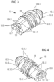
- the main closing element 18 forms a central channel 18.1 and 18.2 extending through said element, the pilot closing element 22 being configured for closing that channel under the resilient force of the first compression spring 26.
- the channel in the main closing element 18 comprises a through-hole 18.1 that is proximal to the main seat 20 and a bore that is distal to the main seat 20.
- the pilot closing element 22 comprises a proximal portion 22.1 of a reduced diameter extending through the through-hole 18.1, a distal portion 22.2 located in the bore 18.2 and a collar portion 22.3 located between the proximal and distal portions and housed in a sliding fashion in the bore 18.2.
- the pin-shaped proximal portion 22.1 of the pilot closing element 22 protrudes out of the main closing element 18 and is in contact or at least in vis-à-vis of the push rod 14.3 of the actuating device 14.
- the push rod 14.3 will be moved, for instance lowered, so as to move the pilot closing element 22 away from the pilot seat 24 and open the gas passage through the channel 18.1 and 18.2 in the main closing element 18.
- the first compression spring 26 will be further compressed and transmit a force to the main closing element 18 tending to move it away from its seat 20.
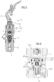
- Figures 7 and 8 are sectional views of a valve according to the invention, in a totally opened state.
- the rear face 18.7 of the main closing element 18 abuts against a circular shoulder 34.5 formed in the body 4 between the second bore 34.2 and a third bore 34.4 of a lower diameter.
- the transversal cut-outs 18.8 in the rear face 18.7 form the gas passage 10 at the circular shoulder 34.5. In that position of the main closing element 18, the force resulting of the gas pressure on both sides of the main closing element 18 is minimum.
Landscapes
- Engineering & Computer Science (AREA)
- General Engineering & Computer Science (AREA)
- Mechanical Engineering (AREA)
- Lift Valve (AREA)
- Fluid-Driven Valves (AREA)
Applications Claiming Priority (3)
| Application Number | Priority Date | Filing Date | Title |
|---|---|---|---|
| LU101328A LU101328B1 (en) | 2019-07-26 | 2019-07-26 | Differential pressure opening and excess flow closing valve for gas cylinder |
| EP20742254.4A EP4004428B1 (fr) | 2019-07-26 | 2020-07-17 | Ouverture de pression différentielle et soupape de fermeture d'un écoulement en excès pour bouteille à gaz |
| PCT/EP2020/070366 WO2021018642A1 (fr) | 2019-07-26 | 2020-07-17 | Ouverture de pression différentielle et soupape de fermeture d'un écoulement en excès pour bouteille à gaz |
Related Parent Applications (2)
| Application Number | Title | Priority Date | Filing Date |
|---|---|---|---|
| EP20742254.4A Division-Into EP4004428B1 (fr) | 2019-07-26 | 2020-07-17 | Ouverture de pression différentielle et soupape de fermeture d'un écoulement en excès pour bouteille à gaz |
| EP20742254.4A Division EP4004428B1 (fr) | 2019-07-26 | 2020-07-17 | Ouverture de pression différentielle et soupape de fermeture d'un écoulement en excès pour bouteille à gaz |
Publications (2)
| Publication Number | Publication Date |
|---|---|
| EP4538587A2 true EP4538587A2 (fr) | 2025-04-16 |
| EP4538587A3 EP4538587A3 (fr) | 2025-06-25 |
Family
ID=67539555
Family Applications (2)
| Application Number | Title | Priority Date | Filing Date |
|---|---|---|---|
| EP20742254.4A Active EP4004428B1 (fr) | 2019-07-26 | 2020-07-17 | Ouverture de pression différentielle et soupape de fermeture d'un écoulement en excès pour bouteille à gaz |
| EP25160450.0A Pending EP4538587A3 (fr) | 2019-07-26 | 2020-07-17 | Ouverture de pression différentielle et soupape de fermeture d'un écoulement en excès pour bouteille à gaz |
Family Applications Before (1)
| Application Number | Title | Priority Date | Filing Date |
|---|---|---|---|
| EP20742254.4A Active EP4004428B1 (fr) | 2019-07-26 | 2020-07-17 | Ouverture de pression différentielle et soupape de fermeture d'un écoulement en excès pour bouteille à gaz |
Country Status (4)
| Country | Link |
|---|---|
| US (1) | US11927308B2 (fr) |
| EP (2) | EP4004428B1 (fr) |
| LU (1) | LU101328B1 (fr) |
| WO (1) | WO2021018642A1 (fr) |
Families Citing this family (2)
| Publication number | Priority date | Publication date | Assignee | Title |
|---|---|---|---|---|
| LU101208B1 (en) * | 2019-04-26 | 2020-10-26 | Luxembourg Patent Co | Lever valve with securing hook |
| US12292126B2 (en) * | 2023-06-07 | 2025-05-06 | Scott Wu | Inflator valve connector |
Citations (3)
| Publication number | Priority date | Publication date | Assignee | Title |
|---|---|---|---|---|
| US3844312A (en) | 1971-11-22 | 1974-10-29 | Fisher Controls Co | Rapid equalizing tight shut-off internal control valve |
| US20100252770A1 (en) | 2009-04-03 | 2010-10-07 | Chun Lin | Redundant metal-to-metal seals for use with internal valves |
| US20160097444A1 (en) | 2014-10-03 | 2016-04-07 | Emerson Process Management Regulator Technologies, | Cam apparatus for use with valves |
Family Cites Families (12)
| Publication number | Priority date | Publication date | Assignee | Title |
|---|---|---|---|---|
| US3545484A (en) * | 1967-12-06 | 1970-12-08 | Eaton Yale & Towne | Pilot-operated valve |
| US4077422A (en) * | 1975-11-17 | 1978-03-07 | Said Robie G. Brinkley, By Said Gerry D. Welton | Flow control means for compressed gas cylinders |
| US5275086A (en) * | 1992-08-27 | 1994-01-04 | Unlimited Solutions, Inc. | Fluid actuator with internal pressure relief valve |
| JP3745427B2 (ja) * | 1995-11-14 | 2006-02-15 | Smc株式会社 | 真空圧制御用スロー排気バルブ |
| US5794652A (en) * | 1995-11-30 | 1998-08-18 | Konan Electric Co., Ltd. | Relief valve |
| US5871156A (en) * | 1997-05-02 | 1999-02-16 | Anthony Manufacturing, Co. | Sprinkler with removable valve seat |
| KR100756651B1 (ko) * | 2005-07-29 | 2007-09-07 | 신일환 | 액화석유가스용기용 과류차단밸브 |
| JP2007278484A (ja) * | 2006-04-12 | 2007-10-25 | Neriki:Kk | 過流防止弁 |
| US7984890B2 (en) * | 2008-02-26 | 2011-07-26 | Incova Technologies, Inc. | Pilot operated valve with fast closing poppet |
| US8662110B2 (en) * | 2010-06-10 | 2014-03-04 | Control Components, Inc. | Shut-off trim including spring loaded check valve |
| JP5894558B2 (ja) * | 2013-04-25 | 2016-03-30 | 川崎重工業株式会社 | 過流防止機能付き弁装置 |
| LU100263B1 (en) * | 2017-05-26 | 2019-01-04 | Luxembourg Patent Co | Compact gas cylinder valve with residual pressure function |
-
2019
- 2019-07-26 LU LU101328A patent/LU101328B1/en active IP Right Grant
-
2020
- 2020-07-17 WO PCT/EP2020/070366 patent/WO2021018642A1/fr not_active Ceased
- 2020-07-17 EP EP20742254.4A patent/EP4004428B1/fr active Active
- 2020-07-17 US US17/630,406 patent/US11927308B2/en active Active
- 2020-07-17 EP EP25160450.0A patent/EP4538587A3/fr active Pending
Patent Citations (3)
| Publication number | Priority date | Publication date | Assignee | Title |
|---|---|---|---|---|
| US3844312A (en) | 1971-11-22 | 1974-10-29 | Fisher Controls Co | Rapid equalizing tight shut-off internal control valve |
| US20100252770A1 (en) | 2009-04-03 | 2010-10-07 | Chun Lin | Redundant metal-to-metal seals for use with internal valves |
| US20160097444A1 (en) | 2014-10-03 | 2016-04-07 | Emerson Process Management Regulator Technologies, | Cam apparatus for use with valves |
Also Published As
| Publication number | Publication date |
|---|---|
| EP4004428B1 (fr) | 2025-11-05 |
| US11927308B2 (en) | 2024-03-12 |
| EP4538587A3 (fr) | 2025-06-25 |
| LU101328B1 (en) | 2021-01-28 |
| US20220282836A1 (en) | 2022-09-08 |
| EP4004428A1 (fr) | 2022-06-01 |
| EP4004428C0 (fr) | 2025-11-05 |
| WO2021018642A1 (fr) | 2021-02-04 |
Similar Documents
| Publication | Publication Date | Title |
|---|---|---|
| EP0698759B1 (fr) | Vanne de limitation de débit | |
| US9057448B2 (en) | Internal relief valve for a valve actuator | |
| US2864628A (en) | Quick disconnect coupling | |
| US9416886B2 (en) | Hydraulic coupling member with pressure-relieving poppet valve | |
| EP3631284B1 (fr) | Soupape de bouteille de gaz compacte avec fonction de pression résiduelle | |
| BR0101219B1 (pt) | conexão hidráulica subaquática. | |
| US9791050B2 (en) | Gas shut-off device | |
| EP4004428B1 (fr) | Ouverture de pression différentielle et soupape de fermeture d'un écoulement en excès pour bouteille à gaz | |
| NO176531B (no) | Hydraulisk kopling | |
| WO2016003684A1 (fr) | Vanne à bille et son procédé de fonctionnement | |
| EP3295013B1 (fr) | Vanne electromagnetique avec vanne principale et vanne pilote actionnées magnétiquement | |
| AU2003201429B2 (en) | Valve element | |
| US6237632B1 (en) | Undersea hydraulic coupling member with primary and secondary poppet valves | |
| US6474359B1 (en) | Undersea hydraulic coupling member | |
| US20050087245A1 (en) | Hydraulic coupling comprising a pressure bleed device | |
| EP1486712B1 (fr) | Soupape a trois voies | |
| CA1090153A (fr) | Dispositif d'accouplement pour deux tiges | |
| WO2018084750A1 (fr) | Vanne et unité de commande l'utilisant | |
| US4176679A (en) | Check valve | |
| AU2006222658B2 (en) | Pipe Disconnector with Increased Sealing Power | |
| US2689581A (en) | High-pressure safety relief valve | |
| RU191458U1 (ru) | Клапан отсечной | |
| NZ217527A (en) | Pressure control valve: balanced pressures on shuttle when closed | |
| SK462013U1 (sk) | Safety industrial lock and method of its function |
Legal Events
| Date | Code | Title | Description |
|---|---|---|---|
| PUAI | Public reference made under article 153(3) epc to a published international application that has entered the european phase |
Free format text: ORIGINAL CODE: 0009012 |
|
| STAA | Information on the status of an ep patent application or granted ep patent |
Free format text: STATUS: THE APPLICATION HAS BEEN PUBLISHED |
|
| AC | Divisional application: reference to earlier application |
Ref document number: 4004428 Country of ref document: EP Kind code of ref document: P |
|
| AK | Designated contracting states |
Kind code of ref document: A2 Designated state(s): AL AT BE BG CH CY CZ DE DK EE ES FI FR GB GR HR HU IE IS IT LI LT LU LV MC MK MT NL NO PL PT RO RS SE SI SK SM TR |
|
| PUAL | Search report despatched |
Free format text: ORIGINAL CODE: 0009013 |
|
| AK | Designated contracting states |
Kind code of ref document: A3 Designated state(s): AL AT BE BG CH CY CZ DE DK EE ES FI FR GB GR HR HU IE IS IT LI LT LU LV MC MK MT NL NO PL PT RO RS SE SI SK SM TR |
|
| RIC1 | Information provided on ipc code assigned before grant |
Ipc: F17C 13/04 20060101AFI20250521BHEP |
|
| STAA | Information on the status of an ep patent application or granted ep patent |
Free format text: STATUS: REQUEST FOR EXAMINATION WAS MADE |
|
| 17P | Request for examination filed |
Effective date: 20251219 |
|
| RAP3 | Party data changed (applicant data changed or rights of an application transferred) |
Owner name: ROTAREX S.A. |