EP4538593A1 - Lampe de véhicule - Google Patents
Lampe de véhicule Download PDFInfo
- Publication number
- EP4538593A1 EP4538593A1 EP23819650.5A EP23819650A EP4538593A1 EP 4538593 A1 EP4538593 A1 EP 4538593A1 EP 23819650 A EP23819650 A EP 23819650A EP 4538593 A1 EP4538593 A1 EP 4538593A1
- Authority
- EP
- European Patent Office
- Prior art keywords
- light
- lens
- vehicle lamp
- distribution pattern
- light distribution
- Prior art date
- Legal status (The legal status is an assumption and is not a legal conclusion. Google has not performed a legal analysis and makes no representation as to the accuracy of the status listed.)
- Pending
Links
Images


Classifications
-
- F—MECHANICAL ENGINEERING; LIGHTING; HEATING; WEAPONS; BLASTING
- F21—LIGHTING
- F21S—NON-PORTABLE LIGHTING DEVICES; SYSTEMS THEREOF; VEHICLE LIGHTING DEVICES SPECIALLY ADAPTED FOR VEHICLE EXTERIORS
- F21S41/00—Illuminating devices specially adapted for vehicle exteriors, e.g. headlamps
- F21S41/20—Illuminating devices specially adapted for vehicle exteriors, e.g. headlamps characterised by refractors, transparent cover plates, light guides or filters
- F21S41/25—Projection lenses
- F21S41/265—Composite lenses; Lenses with a patch-like shape
-
- F—MECHANICAL ENGINEERING; LIGHTING; HEATING; WEAPONS; BLASTING
- F21—LIGHTING
- F21S—NON-PORTABLE LIGHTING DEVICES; SYSTEMS THEREOF; VEHICLE LIGHTING DEVICES SPECIALLY ADAPTED FOR VEHICLE EXTERIORS
- F21S41/00—Illuminating devices specially adapted for vehicle exteriors, e.g. headlamps
- F21S41/10—Illuminating devices specially adapted for vehicle exteriors, e.g. headlamps characterised by the light source
- F21S41/14—Illuminating devices specially adapted for vehicle exteriors, e.g. headlamps characterised by the light source characterised by the type of light source
- F21S41/141—Light emitting diodes [LED]
- F21S41/143—Light emitting diodes [LED] the main emission direction of the LED being parallel to the optical axis of the illuminating device
-
- F—MECHANICAL ENGINEERING; LIGHTING; HEATING; WEAPONS; BLASTING
- F21—LIGHTING
- F21S—NON-PORTABLE LIGHTING DEVICES; SYSTEMS THEREOF; VEHICLE LIGHTING DEVICES SPECIALLY ADAPTED FOR VEHICLE EXTERIORS
- F21S41/00—Illuminating devices specially adapted for vehicle exteriors, e.g. headlamps
- F21S41/20—Illuminating devices specially adapted for vehicle exteriors, e.g. headlamps characterised by refractors, transparent cover plates, light guides or filters
- F21S41/25—Projection lenses
- F21S41/255—Lenses with a front view of circular or truncated circular outline
-
- F—MECHANICAL ENGINEERING; LIGHTING; HEATING; WEAPONS; BLASTING
- F21—LIGHTING
- F21S—NON-PORTABLE LIGHTING DEVICES; SYSTEMS THEREOF; VEHICLE LIGHTING DEVICES SPECIALLY ADAPTED FOR VEHICLE EXTERIORS
- F21S41/00—Illuminating devices specially adapted for vehicle exteriors, e.g. headlamps
- F21S41/20—Illuminating devices specially adapted for vehicle exteriors, e.g. headlamps characterised by refractors, transparent cover plates, light guides or filters
- F21S41/25—Projection lenses
- F21S41/275—Lens surfaces, e.g. coatings or surface structures
-
- F—MECHANICAL ENGINEERING; LIGHTING; HEATING; WEAPONS; BLASTING
- F21—LIGHTING
- F21S—NON-PORTABLE LIGHTING DEVICES; SYSTEMS THEREOF; VEHICLE LIGHTING DEVICES SPECIALLY ADAPTED FOR VEHICLE EXTERIORS
- F21S41/00—Illuminating devices specially adapted for vehicle exteriors, e.g. headlamps
- F21S41/20—Illuminating devices specially adapted for vehicle exteriors, e.g. headlamps characterised by refractors, transparent cover plates, light guides or filters
- F21S41/285—Refractors, transparent cover plates, light guides or filters not provided in groups F21S41/24 - F21S41/2805
-
- F—MECHANICAL ENGINEERING; LIGHTING; HEATING; WEAPONS; BLASTING
- F21—LIGHTING
- F21S—NON-PORTABLE LIGHTING DEVICES; SYSTEMS THEREOF; VEHICLE LIGHTING DEVICES SPECIALLY ADAPTED FOR VEHICLE EXTERIORS
- F21S41/00—Illuminating devices specially adapted for vehicle exteriors, e.g. headlamps
- F21S41/30—Illuminating devices specially adapted for vehicle exteriors, e.g. headlamps characterised by reflectors
- F21S41/32—Optical layout thereof
- F21S41/322—Optical layout thereof the reflector using total internal reflection
-
- F—MECHANICAL ENGINEERING; LIGHTING; HEATING; WEAPONS; BLASTING
- F21—LIGHTING
- F21S—NON-PORTABLE LIGHTING DEVICES; SYSTEMS THEREOF; VEHICLE LIGHTING DEVICES SPECIALLY ADAPTED FOR VEHICLE EXTERIORS
- F21S41/00—Illuminating devices specially adapted for vehicle exteriors, e.g. headlamps
- F21S41/40—Illuminating devices specially adapted for vehicle exteriors, e.g. headlamps characterised by screens, non-reflecting members, light-shielding members or fixed shades
- F21S41/43—Illuminating devices specially adapted for vehicle exteriors, e.g. headlamps characterised by screens, non-reflecting members, light-shielding members or fixed shades characterised by the shape thereof
-
- F—MECHANICAL ENGINEERING; LIGHTING; HEATING; WEAPONS; BLASTING
- F21—LIGHTING
- F21S—NON-PORTABLE LIGHTING DEVICES; SYSTEMS THEREOF; VEHICLE LIGHTING DEVICES SPECIALLY ADAPTED FOR VEHICLE EXTERIORS
- F21S43/00—Signalling devices specially adapted for vehicle exteriors, e.g. brake lamps, direction indicator lights or reversing lights
- F21S43/10—Signalling devices specially adapted for vehicle exteriors, e.g. brake lamps, direction indicator lights or reversing lights characterised by the light source
- F21S43/13—Signalling devices specially adapted for vehicle exteriors, e.g. brake lamps, direction indicator lights or reversing lights characterised by the light source characterised by the type of light source
- F21S43/14—Light emitting diodes [LED]
-
- F—MECHANICAL ENGINEERING; LIGHTING; HEATING; WEAPONS; BLASTING
- F21—LIGHTING
- F21S—NON-PORTABLE LIGHTING DEVICES; SYSTEMS THEREOF; VEHICLE LIGHTING DEVICES SPECIALLY ADAPTED FOR VEHICLE EXTERIORS
- F21S43/00—Signalling devices specially adapted for vehicle exteriors, e.g. brake lamps, direction indicator lights or reversing lights
- F21S43/20—Signalling devices specially adapted for vehicle exteriors, e.g. brake lamps, direction indicator lights or reversing lights characterised by refractors, transparent cover plates, light guides or filters
- F21S43/2605—Refractors
- F21S43/2621—Refractors characterised by the properties of the light beam shaping surface
- F21S43/26231—Refractors characterised by the properties of the light beam shaping surface collimating, focusing, condensing or projecting beams, e.g. projection lenses or Fresnel lenses
-
- F—MECHANICAL ENGINEERING; LIGHTING; HEATING; WEAPONS; BLASTING
- F21—LIGHTING
- F21S—NON-PORTABLE LIGHTING DEVICES; SYSTEMS THEREOF; VEHICLE LIGHTING DEVICES SPECIALLY ADAPTED FOR VEHICLE EXTERIORS
- F21S43/00—Signalling devices specially adapted for vehicle exteriors, e.g. brake lamps, direction indicator lights or reversing lights
- F21S43/20—Signalling devices specially adapted for vehicle exteriors, e.g. brake lamps, direction indicator lights or reversing lights characterised by refractors, transparent cover plates, light guides or filters
- F21S43/2605—Refractors
- F21S43/2641—Refractors or refracting portions characterised by their relative arrangement, e.g. parallel refractors
- F21S43/26411—Two or more successive refractors
-
- F—MECHANICAL ENGINEERING; LIGHTING; HEATING; WEAPONS; BLASTING
- F21—LIGHTING
- F21S—NON-PORTABLE LIGHTING DEVICES; SYSTEMS THEREOF; VEHICLE LIGHTING DEVICES SPECIALLY ADAPTED FOR VEHICLE EXTERIORS
- F21S43/00—Signalling devices specially adapted for vehicle exteriors, e.g. brake lamps, direction indicator lights or reversing lights
- F21S43/20—Signalling devices specially adapted for vehicle exteriors, e.g. brake lamps, direction indicator lights or reversing lights characterised by refractors, transparent cover plates, light guides or filters
- F21S43/2605—Refractors
- F21S43/2641—Refractors or refracting portions characterised by their relative arrangement, e.g. parallel refractors
- F21S43/26421—Refractors comprising a plurality of non-successive refracting portions
-
- F—MECHANICAL ENGINEERING; LIGHTING; HEATING; WEAPONS; BLASTING
- F21—LIGHTING
- F21W—INDEXING SCHEME ASSOCIATED WITH SUBCLASSES F21K, F21L, F21S and F21V, RELATING TO USES OR APPLICATIONS OF LIGHTING DEVICES OR SYSTEMS
- F21W2102/00—Exterior vehicle lighting devices for illuminating purposes
- F21W2102/10—Arrangement or contour of the emitted light
- F21W2102/13—Arrangement or contour of the emitted light for high-beam region or low-beam region
- F21W2102/135—Arrangement or contour of the emitted light for high-beam region or low-beam region the light having cut-off lines, i.e. clear borderlines between emitted regions and dark regions
- F21W2102/155—Arrangement or contour of the emitted light for high-beam region or low-beam region the light having cut-off lines, i.e. clear borderlines between emitted regions and dark regions having inclined and horizontal cutoff lines
-
- F—MECHANICAL ENGINEERING; LIGHTING; HEATING; WEAPONS; BLASTING
- F21—LIGHTING
- F21Y—INDEXING SCHEME ASSOCIATED WITH SUBCLASSES F21K, F21L, F21S and F21V, RELATING TO THE FORM OR THE KIND OF THE LIGHT SOURCES OR OF THE COLOUR OF THE LIGHT EMITTED
- F21Y2115/00—Light-generating elements of semiconductor light sources
- F21Y2115/10—Light-emitting diodes [LED]
Definitions
- the present disclosure relates to a vehicle lamp.
- Patent Literature 1 describes a configuration including a central region centered on an optical axis extending in a front-rear direction of the lamp and a peripheral region located around the central region.
- a plurality of total reflection prism elements which allow light from a light source to be incident and then totally reflected toward the front of the lamp, are formed on a rear surface of the peripheral region in a state of being aligned in a concentric circular form centered on the optical axis.
- a vehicle lamp configured to form a necessary light distribution pattern by radiating light emitted from a light source toward the front of the lamp through a microlens array.
- the total reflection prism elements formed at the outer peripheral edge portion inevitably increase in size, resulting in a significant change in thickness at the outer peripheral edge portion of the lens. For this reason, when forming a lens, it becomes difficult to precisely form a total reflection prism element at the outer peripheral edge portion, making it difficult to perform high-precision light distribution control with this lens.
- the light emitted from the light source, arriving at the outer peripheral edge portion has a considerably large opening angle with respect to the optical axis.
- the reflected light from the plurality of total reflection prism elements becomes uneven in intensity depending on the radial position, making it difficult to perform high-precision light distribution control with this lens.
- a plurality of lens elements for controlling the emission of light arriving from a plurality of total reflection prism elements are formed on the front surface of the lens in a state divided into a shape of vertical and horizontal grids, it becomes possible to form a light distribution pattern having a cutoff line at an upper end portion by appropriately adjusting the orientation of the plurality of lens elements.
- the collimator lens is configured as a large block-shaped light-transmitting member, which results in an increased depth dimension of the vehicle lamp.
- an object of the present disclosure is to provide a vehicle lamp configured to radiate light emitted from a light source toward the front of the lamp through a lens, which enables formation of a light distribution pattern with a clear cutoff line.
- the present disclosure seeks to achieve the above object by devising a configuration for a rear surface in a region around a lens.
- each of the "first annular concave curved surface” and the “second annular concave curved surface” is not particularly limited.
- the present disclosure seeks to achieve the above object by additionally arranging a condenser lens between a light source and a lens.
- the specific curvature of the "annular concave curved surface” is not particularly limited.
- the present disclosure seeks to achieve the above objects by devising a configuration for a front surface of a lens.
- a vehicle lamp according to a third aspect of the present disclosure includes:
- the type of "light source” is not particularly limited, and for example, a light-emitting element such as a light-emitting diode, a light source bulb, and the like can be adopted.
- the present disclosure seeks to achieve the above object by devising a configuration for a collimator lens.
- a vehicle lamp according to a fourth aspect of the present disclosure includes:
- the vehicle lamp according to the first aspect of the present disclosure is configured to radiate light emitted from the light source toward the front of the lamp through the lens.
- the plurality of total reflection prism elements configured to allow light emitted from the light source to be incident and then totally reflected toward the front of the lamp are formed on the rear surface of the peripheral region located around the central region centered on the optical axis extending in the front-rear direction of the lamp in the lens in a state of being aligned in a concentric circular form centered on the optical axis. Therefore, the light emitted from the light source can be used as forward-radiated light over a wide area.
- the rear surface of the peripheral region of the lens is divided into the inner periphery-side region and the outer periphery-side region, and the plurality of total reflection prism elements form the first annular concave curved surface centered on the optical axis as an envelope surface in the inner periphery-side region and form the second annular concave curved surface centered on the optical axis as an envelope surface in the outer periphery-side region, the following effects can be achieved.
- the plurality of total reflection prism elements form the second annular concave curved surface centered on the optical axis as an envelope surface in the outer periphery-side region of the rear surface of the peripheral region, so light emitted from the light source incident on the outer periphery-side region can also be totally reflected toward the front of the lamp as light with substantially uniform brightness by the plurality of total reflection prism elements.
- a vehicle lamp configured to radiate light emitted from a light source toward the front of the lamp through a lens
- light distribution control by the lens can be performed with high precision while sufficiently securing an amount of light emitted from the outer peripheral edge portion of the lens.
- the vehicle lamp according to the second aspect of the present disclosure is configured to radiate light emitted from the light source toward the front of the lamp through the lens.
- the plurality of total reflection prism elements configured to allow light emitted from the light source to be incident and then totally reflected toward the front of the lamp are formed on the rear surface of the peripheral region located around the central region centered on the optical axis extending in the front-rear direction of the lamp in the lens in a state of being aligned in a concentric circular form centered on the optical axis. Therefore, the light emitted from the light source can be used as forward-radiated light over a wide area.
- the plurality of total reflection prism elements form an annular concave curved surface centered on the optical axis as an envelope surface, a sufficient amount of light can be obtained even for light emitted from the light source toward the outer peripheral edge portion of the lens.
- the condenser lens configured to allow light emitted from the light source to be incident on the lens in a condensed state is arranged between the light source and the lens, an opening angle of light emitted from the light source, arriving at the outer peripheral edge portion of the peripheral region of the lens, with respect to the optical axis can be reduced. Accordingly, it is possible to prevent the intensity of reflected light from the plurality of total reflection prism elements from becoming uneven depending on the radial position, thereby enabling light distribution control by the lens to be performed with high precision.
- a vehicle lamp configured to radiate light emitted from a light source toward the front of the lamp through a lens
- light distribution control by the lens can be performed with high precision while sufficiently securing an amount of light emitted from the outer peripheral edge portion of the lens.
- the condenser lens may be configured as a plano-convex lens whose front surface is formed into a convex curved surface shape. According to this configuration, it becomes possible to use the light emitted from the light source as forward-radiated light over a wider area.
- a plurality of condenser lens elements aligned in a concentric circular form centered on the optical axis may be configured to be formed on the front surface of the condenser lens. According to this configuration, a region where light emitted from the light source is incident on the lens through the condenser lens can be appropriately set by a surface shape of each of the plurality of condenser lens elements, resulting in enhanced degree of freedom of light distribution control by the lens.
- a plurality of lens elements configured to control emission of light arriving from the plurality of total reflection prism elements may be formed on the front surface of the lens. According to this configuration, the degree of freedom of light distribution control can be further enhanced.
- the plurality of lens elements since at least some of the plurality of lens elements have vertical inclination angles set to different values from each other among the plurality of lens elements constituting a vertical row of the vertical and horizontal grids, it becomes possible to align positions of upper end edges of a light distribution pattern formed by light emitted from each of the plurality of lens elements, thereby making it easy to form a light distribution pattern having a cutoff line at an upper end portion.
- a vehicle lamp configured to radiate light from a light source toward the front of the lamp through a lens, it is possible to form a light distribution pattern having a clear cutoff line.
- the plurality of lens elements having vertical inclination angles set to different values from each other may be formed continuously with each other in a vertical row of the vertical and horizontal grids. According to this configuration, it becomes possible to prevent a step from being formed between the plurality of lens elements. Also, it becomes possible to prevent upward scattered light from being unintentionally radiated from a step portion, making it possible to easily maintain a clear cutoff line.
- the front surface of the lens can be made a simpler design, thereby enhancing the appearance of the lens.
- a plurality of lens elements having different horizontal cross-sectional shapes from each other may be provided as the plurality of lens elements having vertical inclination angles set to different values from each other. According to the above configuration, it is possible to form a light distribution pattern having a clear cutoff line while enabling a position of a high-intensity area to be appropriately displaced left or right from the forward-facing direction of the lamp, thereby making it easy to obtain light distribution suitable for vehicle traveling.
- light emitted from the light source incident on the microlens array as parallel light through the collimator lens is condensed by the plurality of condenser lens portions constituting the rear lens array of the microlens array, and the plurality of light source images formed by the condenser lens portions are projected by the plurality of projection lens portions constituting the front lens array of the microlens array, respectively. Therefore, it becomes possible to easily form a light distribution pattern in any shape.
- the plurality of total reflection prism elements configured to allow light emitted from the light source to be incident and then totally reflected toward the front of the lamp are formed on the rear side of the peripheral region located around the central region centered on the optical axis extending in the front-rear direction of the lamp in the collimator lens in a state of being aligned in a concentric circular form centered on the optical axis. Therefore, the light emitted from the light source can be used as forward-radiated light over a wide area while suppressing the depth dimension of the vehicle lamp.
- the plurality of total reflection prism elements form an annular concave curved surface centered on the optical axis as an envelope surface, a sufficient amount of light can be obtained even for light emitted from the light source toward an outer peripheral edge portion of the collimator lens. Accordingly, the light emitted from the light source can be allowed to be incident on each of the plurality of condenser lens portions as parallel light with substantially uniform brightness, thereby enabling formation of a light distribution pattern with reduced light distribution unevenness.
- a light distribution pattern with reduced light distribution unevenness can be formed while reducing the depth dimension of the vehicle lamp.
- the collimator lens and the rear lens array may be formed integrally. According to this configuration, the depth dimension of the vehicle lamp can be further reduced, and the cost of the vehicle lamp can be reduced by reducing the number of components.
- a light-shielding sheet including a plurality of light-transmitting portions for defining respective outer shapes of the plurality of light source images may be arranged between the rear lens array and the front lens array. According to this configuration, it is possible to form a light distribution pattern corresponding to each size and outer shape of the plurality of light-transmitting portions.
- each of the "plurality of light-transmitting portions” are not particularly limited.
- FIG. 1 is a front view showing a vehicle lamp 10 according to the first embodiment of the present disclosure.
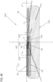
- FIG. 2 is a cross-sectional view taken along line II-II of FIG. 1 .
- a direction indicated by X is "front of the lamp”
- a direction indicated by Y is a “left direction” (or “right direction” when viewed from the front of the lamp) orthogonal to the "front of the lamp”
- a direction indicated by Z is "upper direction.” The same applies to the drawings other than FIGS. 1 and 2 .
- the second lamp unit 40 includes a light-emitting element 42 and a lens 50 arranged on a front side of the lamp relative to the light-emitting element 42, and is configured to radiate light emitted from the light-emitting element 42 toward the front of the lamp through the lens 50.
- the light-emitting elements 22 and 42 of the first and second lamp units 20 and 40 are supported on a lamp body 12 via a common substrate 24, and the lenses 30 and 50 are supported on the lamp body 12 via an attachment structure (not shown).
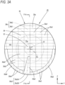
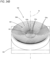
- FIG. 3A is a front view showing the first lamp unit 20.
- FIG. 4A is a cross-sectional view taken along line IVa-IVa of FIG. 3
- FIG. 5 is a cross-sectional view taken along line Va-Va of FIG. 4A .
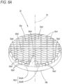
- FIG. 6A is a perspective view showing the lens 30 of the first lamp unit 20 as viewed in a direction of arrow VIa of FIG. 4A
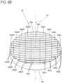
- FIG. 7A is a perspective view showing the lens 30 as viewed in a direction of arrow VIIa of FIG. 4A .
- the lens 30 is an injection-molded product made of transparent resin and has a central region 32 centered on the optical axis Ax and a peripheral region 34 located around the central region 32.
- a rear surface 32b of the central region 32 is configured as a single convex lens surface centered on the optical axis Ax, and is designed to deflect light emitted from the light-emitting element 22 to be incident in a direction close to the optical axis Ax.
- a surface shape of the rear surface 32b is set to guide the light emitted from the reference position of the light-emitting element 22 to a front surface 30a of the lens 30 as parallel light directed toward the forward-facing direction of the lamp.
- a plurality of total reflection prism elements 34s1 are formed on the inner periphery-side region 34b1 in a state of being aligned in a concentric circular form centered on the optical axis Ax, and a plurality of total reflection prism elements 34s2 are formed on the outer periphery-side region 34b2 in a state of being aligned in a concentric circular form centered on the optical axis Ax.
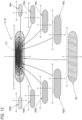
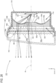
- FIG. 8 is a detailed view of portion VIII of FIG. 5 .
- FIG. 9A is a detailed view of portion IXa of FIG. 8
- FIG. 9B is a detailed view of portion IXb of FIG. 8 .
- the plurality of total reflection prism elements 34s1 positioned in the inner periphery-side region 34b1 form a first annular concave curved surface C1 (a cross-sectional shape is indicated by a two-dot chain line in the drawing) centered on the optical axis Ax as an envelope surface
- the plurality of total reflection prism elements 34s2 positioned in the outer periphery-side region 34b2 form a second annular concave curved surface C2 (a cross-sectional shape is indicated by a two-dot chain line in the drawing) centered on the optical axis Ax as an envelope surface.
- Each of the plurality of total reflection prism elements 34s1 formed in the inner periphery-side region 34b1 is configured to totally reflect light emitted from a first virtual point light source S1 located on a rear side of the lamp relative to the light-emitting surface 22a of the light-emitting element 22 as parallel light directed toward the forward-facing direction of the lamp, within a plane including the optical axis Ax.
- the first virtual point light source S1 is located on an opposite side to an incidence region, in the inner periphery-side region 34b1, of light emitted from the first virtual point light source S1 with respect to the optical axis Ax.
- the first virtual point light source S1 is located at an intersection of a straight line L1a connecting an inner peripheral edge of the inner periphery-side region 34bl and a right end edge (a left end edge in FIG. 8 ) of the light-emitting surface 22a of the light-emitting element 22 and a straight line L1b connecting an outer peripheral edge of the inner periphery-side region 34b1 and a left end edge of the light-emitting surface 22a of the light-emitting element 22.
- each of the plurality of total reflection prism elements 34s2 formed in the outer periphery-side region 34b2 is configured to totally reflect light emitted from a second virtual point light source S2 located on a rear side of the lamp relative to the light-emitting surface 22a of the light-emitting element 22 and on a front side of the lamp relative to the first virtual point light source S1 as parallel light directed toward the forward-facing direction of the lamp, within the plane including the optical axis Ax.
- the second virtual point light source S2 is located on an opposite side to an incidence region, in the outer periphery-side region 34b2, of light emitted from the second virtual point light source S2 with respect to the optical axis Ax.
- the second virtual point light source S2 is located at an intersection of a straight line L2a connecting an inner peripheral edge of the outer periphery-side region 34b2 and the right end edge of the light-emitting surface 22a of the light-emitting element 22 and a straight line L2b connecting an outer peripheral edge of the outer periphery-side region 34b2 and the left end edge of the light-emitting surface 22a of the light-emitting element 22.
- the first and second virtual point light sources S1 and S2 are also arranged to draw annular trajectories centered on the optical axis Ax.
- a pitch of the plurality of total reflection prism elements 34s1 and a curvature of the first annular concave curved surface C1 are set such that the light emitted from the light-emitting element 22 is incident approximately equally on each of the plurality of total reflection prism elements 34s1.
- a pitch of the plurality of total reflection prism elements 34s2 and a curvature of the second annular concave curved surface C2 are set such that the light emitted from the light-emitting element 22 is incident approximately equally on each of the plurality of total reflection prism elements 34s2.
- the plurality of total reflection prism elements 34s1 formed in the inner periphery-side region 34b1 have a cross-sectional shape in which the total reflection prism elements 34s1 located closer to the outer peripheral edge of the inner periphery-side region 34b1 are larger than the total reflection prism elements 34s1 located closer to the inner peripheral edge.
- the plurality of total reflection prism elements 34s2 formed in the outer periphery-side region 34b2 have a cross-sectional shape in which the total reflection prism elements 34s2 located closer to the outer peripheral edge of the outer periphery-side region 34b2 are larger than the total reflection prism elements 34s1 located closer to the inner peripheral edge.
- the front surface 30a of the lens 30 is divided into five emission regions 30al, 30a2, 30a3, 30a4, and 30a5.
- the emission regions 30a2 and 30a4 are divided into a shape of vertical stripes (e.g., with a horizontal width of about 2 mm) with each of convex curve-shaped lens elements 30s2 and 30s4 assigned to each vertical striped region.
- the emission region 30a5 is divided into a shape of vertical and horizontal grids with a convex curved lens element 30s5 assigned to each grid.
- each lens element 30s5 is configured to emit light from the light-emitting element 22, arriving as parallel light from the rear surfaces 32b and 34b of the lens 30, toward the front of the lamp while slightly deflecting the light downward and then widely diffusing the deflected light in the left direction.
- the configuration and arrangement of the light-emitting element 42 are similar to those of the light-emitting element 22 of the first lamp unit 20
- the basic configuration and arrangement of the lens 50 are similar to those of the lens 30 of the first lamp unit 20.
- a configuration of a front surface 50a is different from that of the lens 30.
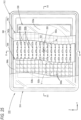
- the front surface 50a of the lens 50 is divided into nine emission regions 50al, 50a2L, 50a2R, 50a3L, 50a3R, 50a4L, 50a4R, 50a5L, and 50a5R, each formed with a plurality of lens elements (which will be described below).
- the nine emission regions 50al to 50a5R are each formed as a band-shaped region extending in the vertical direction along a cylindrical surface bulging toward the front side of the lamp and extending in the vertical direction.
- the emission region 50al is formed with a wide width (for example, a width of about 6 mm) centered on the optical axis Ax, and on the left and right sides thereof, the emission regions 50a2L and 50a2R, the emission regions 50a3L and 50a3R, the emission regions 50a4L and 50a4R, and the emission regions 50a5L and 50a5R are formed to be adjacent in this order, each with a width of, for example, about 4 mm.
- a wide width for example, a width of about 6 mm
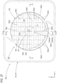
- FIG. 10 is a perspective view showing a low beam light distribution pattern PL-1 formed on a virtual vertical screen placed 25 m ahead of the lamp by radiated light from the vehicle lamp 10.
- the stepped cutoff line CL has a shape in which a lower cutoff line CL1 and an upper cutoff line CL2, offset vertically and extending horizontally, are connected via a slope portion CL3.
- the stepped cutoff line CL is formed such that the lower cutoff line CL1 is positioned on the opposite lane side with respect to a V-V line, which is a vertical line passing through an H-V vanishing point in the forward-facing direction of the lamp, and the slope portion CL3 and the upper cutoff line CL2 are positioned on the own lane side.
- the upper cutoff line CL2 is positioned slightly above an H-H line, which is a horizontal line passing through H-V
- an elbow point E which is an intersection of the lower cutoff line CL1 and the slope portion CL3, is located about 0.5 to 0.6° below H-V, and the slope portion CL3 extends obliquely in the upper left direction from the elbow point E at an inclination angle of 15° with respect to the horizontal direction.
- a high-intensity region HZ is formed near the lower left of the elbow point E.
- the low beam light distribution pattern PL-1 is formed as a combined light distribution pattern in which a first light distribution pattern PL-1A formed by radiated light from the first lamp unit 20 and a second light distribution pattern PL-1B formed by radiated light from the second lamp unit 40 are superimposed.
- FIG. 11 is a view showing the first light distribution pattern PL-1A.
- the light distribution pattern PA2 is a light distribution pattern formed by light emitted from the emission region 30a2 on the front surface 30a of the lens 30, and is formed as a horizontally long bright light distribution pattern expanding rightward from the vicinity of the V-V line with a narrow vertical width in the vicinity below the H-H line.
- the light distribution pattern PA2 is designed to form the lower cutoff line CL1 of the low beam light distribution pattern PL-1 by its upper end edge.
- Such a light distribution pattern PA2 is due to the fact that an opening angle of the light-emitting surface 22a of the light-emitting element 22 from the outer peripheral edge portion in the outer periphery-side region 34b2 of the peripheral region 34 becomes small, and therefore, the light distribution pattern formed by the light emitted from the emission region 30a2 located on the front side of the lamp is likely to be small and bright.
- the light distribution pattern PA3 is a light distribution pattern formed by light emitted from the emission region 30a3 on the front surface 30a of the lens 30, and is formed as a small and bright light distribution pattern extending obliquely upward to the left with a narrow vertical width in the vicinity below the H-V
- the light distribution pattern PA3 is designed to form the slope portion CL3 and a right end portion of the upper cutoff line CL2 of the low beam light distribution pattern PL-1 by its upper end edge. The formation process of the light distribution pattern PA3 will be described below.
- the formation of such a light distribution pattern PA4 is due to the fact that an opening angle of the light-emitting surface 22a of the light-emitting element 22 from the outer peripheral edge portion in the outer periphery-side region 34b2 of the peripheral region 34 becomes small, and therefore, the light distribution pattern formed by the light emitted from the emission region 30a4 located on the front side of the lamp is likely to be small and bright.
- the light distribution pattern PA5 is a light distribution pattern formed by light emitted from the emission region 30a5 on the front surface 30a of the lens 30 and is formed as a horizontally long, relatively bright light distribution pattern expanding leftward from the vicinity of the left side of the V-V line with a relatively narrow vertical width, spanning both the light distribution pattern PA4 and the light distribution pattern PA1, with its right end portion overlapping the light distribution pattern PA3.
- the light distribution pattern PA3 formed by the light emitted from the lens element 30s3 constituting the emission region 30a3 on the front surface 30a of the lens 30 is formed so that its upper end edge extends from the slope portion CL3 to the right end portion of the upper cutoff line CL2 of the low beam light distribution pattern PL-1, as described above.
- the pair of left and right light distribution patterns PB4L and PB4R is light distribution patterns formed by light emitted from the pair of left and right emission regions 50a4L and 50a4R on the front surface 50a of the lens 50 and is horizontally long light distribution patterns smaller than the light distribution patterns PB3L and PB3R and formed in a bilaterally symmetrical positional relationship, with their center positions offset from the V-V line.
- the second light distribution pattern PL-1B is formed as a light distribution pattern having a light intensity distribution in which the light intensity gradually decreases from the V-V line toward both the left and right, thereby effectively suppressing the occurrence of light distribution unevenness.
- the low beam light distribution pattern PL-1 is formed as a combined light distribution pattern of the first light distribution pattern PL-1A and the second light distribution pattern PL-1B, so the high-intensity area HZ formed near the lower left of the elbow point E becomes bright.
- the rear surfaces 34b and 54b of the peripheral regions 34 and 54 are divided into the inner periphery-side regions 34b1 and 54b1 and the outer periphery-side regions 34b2 and 54b2.
- the plurality of total reflection prism elements 34s1 and 54s1 form the first annular concave curved surface C1 centered on the optical axis Ax as an envelope surface, so the light emitted from the light-emitting elements 22 and 42 incident on the inner periphery-side regions 34b1 and 54b1 can be totally reflected toward the front of the lamp as light with approximately uniform brightness by the plurality of total reflection prism elements 34s1 and 54s1.
- the plurality of total reflection prism elements 34s2 and 54s2 form the second annular concave curved surface C2 centered on the optical axis Ax as an envelope surface, so light emitted from the light-emitting elements 22 and 42 incident on the outer periphery-side regions 34b2 and 54b2 can also be totally reflected toward the front of the lamp as light with approximately uniform brightness by the plurality of total reflection prism elements 34s2 and 54s2.
- the light-emitting surface 22a of the light-emitting element 22 has been described as having an outer shape of about 1 ⁇ 1 mm. A light-emitting surface with other shapes can also be used.
- FIG. 14A is a view similar to FIG. 3A , showing a first lamp unit 120 of a vehicle lamp according to the present modified example.
- FIG. 14B is a view similar to FIG. 3B , showing a second lamp unit 140 of the vehicle lamp according to the present modified example.
- the configuration of the second lamp unit 140 is similar to the above embodiment.
- a configuration of a lens 130 of the first lamp unit 120 is partially different from that in the above embodiment.
- a front surface 130a of the lens 130 of the present modified example is divided into five emission regions 130al, 130a2, 130a3, 130a4, and 130a5.
- the front surface 130a of the lens 130 is largely divided into two concentric regions centered on the optical axis Ax, and a pair of upper and lower emission regions 130al and 130a5 is arranged on an inner periphery side, while a pair of left and right emission regions 130a2 and 130a4 and a pair of upper and lower emission regions 130a3 are arranged on an outer periphery side.
- the emission region 130al located at the upper part of the inner periphery side is divided into a shape of vertical and horizontal grids, which are horizontally long, as in the emission region 30al of the lens 30 of the first lamp unit 20 in the above embodiment, and a convex curved lens element 130s1 is assigned to each grid.
- Each lens element 130s1 is configured to emit light from the light-emitting element 22, arriving as parallel light from the rear surfaces 132b and 134b of the lens 130, toward the front of the lamp while deflecting the light downward and then widely diffusing the deflected light in the left-right direction.
- the pair of left and right emission areas 130a2 and 130a4 is divided into two parts vertically and also into vertical stripes, and convex lens elements 130s2 and 130s4 are assigned to the striped regions, respectively.
- Each of the lens elements 130s4 constituting the emission region 130a4 located on the right is configured to emit light from the light-emitting element 22, arriving as parallel light from the rear surface 134b of the lens 130, toward the front of the lamp while slightly deflecting light upward and then widely diffusing the deflected light in the left direction.
- each lens element 130s3 is formed to extend in a direction inclined at an angle of 15° to the left (the right when viewed from the front of the lamp) with respect to the vertical direction, and is configured to emit light from the light-emitting element 22, arriving as parallel light from the rear surface 134b of the lens 130, toward the front of the lamp while slightly deflecting light upward and then slightly deflecting and diffusing the light in a direction orthogonal to the 15° inclined direction.
- the emission region 130a5 located at the lower part of the inner periphery side is divided into vertical stripes, as in the emission region 30a5 of the lens 30 of the first lamp unit 20 in the above embodiment, and a convex curved lens element 130s5 is assigned to each striped region.
- Each lens element 130s5 is configured to emit light from the light-emitting element 22, arriving as parallel light from the rear surfaces 132b and 134b of the lens 130, toward the front of the lamp while slightly deflecting the light downward and then widely diffusing the deflected light in the left direction.
- the second light distribution pattern PL-2B is similar to the second light distribution pattern PL-1B (see FIG. 13 ) formed by radiated light from the second lamp unit 40 of the above embodiment.
- the light distribution pattern PC1 is a light distribution pattern formed by light emitted from the light emission region 130al of the front surface 130a of the lens 130, and is formed as a horizontally long light distribution pattern widely expanding in the left-right direction with a relatively large vertical width below the H-H line.
- the light distribution pattern PC1 is designed to form a wide diffusion area of the low beam light distribution pattern PL-2.
- the light distribution pattern PC2 is a light distribution pattern formed by light emitted from the emission region 130a2 on the front surface 130a of the lens 130, and is formed as a horizontally long bright light distribution pattern expanding rightward from the vicinity of the V-V line with a narrow vertical width in the vicinity below the H-H line.
- the light distribution pattern PC2 is designed to form the lower cutoff line CL1 of the low beam light distribution pattern PL-2 by its upper end edge.
- the light distribution pattern PC3 is a light distribution pattern formed by light emitted from the pair of upper and lower emission regions 130a3 on the front surface 130a of the lens 130, and is formed as a small and bright light distribution pattern extending obliquely upward to the left with a narrow vertical width in the vicinity below the H-V.
- the light distribution pattern PC3 is designed to form the slope portion CL3 of the low beam light distribution pattern PL-2 by its upper end edge.
- the light distribution pattern PC4 is a light distribution pattern formed by light emitted from the emission region 130a4 on the front surface 130a of the lens 130, and is formed as a horizontally long bright light distribution pattern expanding leftward from the vicinity of the left of the V-V line with a narrow vertical width substantially along the H-H line.
- the light distribution pattern PC4 is designed to form the upper cutoff line CL2 of the low beam light distribution pattern PL-2 by its upper end edge. In this case, the light distribution pattern PC4 is formed with its right end portion overlapping the light distribution pattern PC3.
- the light distribution pattern PC5 is a light distribution pattern formed by light emitted from the emission region 130a5 on the front surface 130a of the lens 130 and is formed as a horizontally long, relatively bright light distribution pattern expanding leftward from the vicinity of the left side of the V-V line with a relatively narrow vertical width, spanning both the light distribution pattern PC4 and the light distribution pattern PC1, with its right end portion overlapping the light distribution pattern PC3.
- FIG. 16 is a front view showing a vehicle lamp 310 according to an embodiment of the present disclosure.
- FIG. 17 is a cross-sectional view taken along line II-II of FIG. 16 .
- a direction indicated by X is "front of the lamp”
- a direction indicated by Y is a “left direction” (or “right direction” when viewed from the front of the lamp) orthogonal to the "front of the lamp”
- a direction indicated by Z is "upper direction”
- a vehicle lamp 310 is a headlamp arranged at a front end portion of a vehicle and includes a lamp unit 320 and 320 incorporated in a lamp chamber formed by a lamp body 312 and a transparent light-transmitting cover 314 attached to a front end opening portion thereof.
- the vehicle lamp 310 is configured to form a low beam light distribution pattern (which will be described below) by radiated light from the lamp unit 320.
- each of the plurality of total reflection prism elements 334s is designed to allow light emitted from the reference position of the light-emitting element 322 to be incident while being refracted in a direction away from the optical axis Ax and then to be guided to the front surface 330a of the lens 330 as parallel light directed toward the forward-facing direction of the lamp.
- the emission region 330a5 is divided into a shape of vertical stripes with a convex curved lens element 330s5 assigned to each striped region.
- Each lens element 330s5 is configured to emit light from the light-emitting element 322, arriving as parallel light from the rear surfaces 332b and 334b of the lens 330, toward the front of the lamp while slightly deflecting the light downward and then widely diffusing the deflected light in the left direction.
- the low beam light distribution pattern PL10 is a low beam light distribution pattern of left light distribution, and an upper end portion thereof is formed with a stepped cutoff line CL10.
- Such a light distribution pattern P12 is due to the fact that an opening angle of the light-emitting surface 322a of the light-emitting element 322 from the outer peripheral edge portion in the outer periphery-side region of the peripheral region 334 becomes small, and therefore, the light distribution pattern formed by the light emitted from the emission region 330a2 located on the front side of the lamp is likely to be small and bright.
- the light distribution pattern P14 is a light distribution pattern formed by light emitted from the emission region 330a4 on the front surface 330a of the lens 330, and is formed as a horizontally long bright light distribution pattern expanding leftward from the vicinity of the left of the V-V line with a narrow vertical width substantially along the H-H line.
- the light distribution pattern P14 is designed to form the upper cutoff line CL12 of the low beam light distribution pattern PL10 by its upper end edge. At this time, the light distribution pattern P14 is formed so that a right end portion thereof smoothly connects to and overlaps the light distribution pattern P13.
- the light distribution pattern P15 is a light distribution pattern formed by light emitted from the emission region 330a5 on the front surface 330a of the lens 330 and is formed as a horizontally long, relatively bright light distribution pattern expanding leftward from the vicinity of the left side of the V-V line with a relatively narrow vertical width, spanning both the light distribution pattern P14 and the light distribution pattern P11, with its right end portion overlapping the light distribution pattern P13.
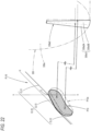
- FIG. 22 is a view for illustrating the formation process of the light distribution pattern P13, and shows a part of the front surface 330a of the lens 330 and a part of the first light distribution pattern PL10 in perspective view, respectively.
- the light distribution pattern P13 formed by the light emitted from the lens element 330s3 constituting the emission region 330a3 on the front surface 330a of the lens 330 is formed so that its upper end edge extends from the slope portion CL13 to the right end portion of the upper cutoff line CL12 of the low beam light distribution pattern PL10, as described above.
- the emission region 330a3 is configured by the single lens element 330s3 and has no steps on its surface, a light pool that causes glare is not unintentionally formed in a space above the slope portion CL13 as part of the light distribution pattern P13.
- an outer diameter D of the lens 330' is set to a value significantly larger than an outer diameter D of the lens 330.
- the plurality of total reflection prism elements 334s which allow light emitted from the light-emitting elements 322 to be incident and then totally reflected toward the front of the lamp, are formed in a state of being aligned in a concentric circular form centered on the optical axis Ax. Therefore, the light emitted from the light-emitting element 322 can be used as forward-radiated light over a wide area.
- the plurality of total reflection prism elements 334s form the annular concave curved surface C10 centered on the optical axis as an envelope surface, a sufficient amount of light can be obtained even for light emitted from the light-emitting element 322 toward the outer peripheral edge portion of the lens 330.
- the condenser lens 340 which allows light emitted from the light-emitting element 322 to be incident on the lens 330 in a condensed state, is arranged between the light-emitting element 322 and the lens 330. Therefore, the opening angle of the light emitted from the light-emitting element 322, arriving at the outer peripheral edge portion of the peripheral region 334 of the lens 330, with respect to the optical axis Ax (i.e., a half value of the maximum radiation angle ⁇ 2) can be reduced. Accordingly, it is possible to prevent the intensity of reflected light from the plurality of total reflection prism elements 334s from becoming uneven depending on the radial position, thereby enabling light distribution control by the lens 330 to be performed with high precision.
- configuring the light emitted from the light-emitting element 322 to be incident on the lens 330 in a state of being condensed by the condenser lens 340 enables the maximum thickness t2 of the peripheral region 334 not to be significantly larger than the maximum thickness t1 of the central region 332.
- the condenser lens 340 of the present embodiment is configured as a plano-convex lens with the front surface 340a formed in a convex curved surface shape and the rear surface 340b formed in a flat surface shape, allowing light emitted from the light-emitting element 322 to be incident over a wide area and used as forward-radiated light.
- the light source of the lamp unit 320 since the light source of the lamp unit 320 includes the light-emitting element 322 arranged with the light-emitting surface 322a facing toward the front of the lamp, it becomes possible to easily form the low beam light distribution pattern PL10 having the stepped cutoff line CL by radiated light from the vehicle lamp 310.
- the lens 330 of the lamp unit 320 has been described as having a circular outer shape when viewed from the front of the lamp.
- a configuration having other outer shapes can also be adopted.
- the low beam light distribution pattern PL10 for left light distribution having the stepped cutoff line CL10 has been described as being formed by radiated light from the vehicle lamp 310.
- a configuration that forms other light distribution patterns can also be adopted.
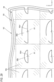
- FIG. 24 is a view similar to FIG. 19 , showing a lamp unit 420 of the vehicle lamp according to the present modified example.
- the rear surface 432b of the central region 432 is configured as a single convex lens surface.
- the rear surface 434b of the peripheral region 434 is divided into an inner periphery-side region 434b1 and an outer periphery-side region 434b2, each formed with a plurality of total reflection prism elements 434s1 and 434s2 aligned in a concentric circular form centered on the optical axis Ax, respectively.
- a plurality of total reflection prism elements 434s1 form a first annular concave curved surface C11 centered on the optical axis Ax as an envelope surface
- a plurality of total reflection prism elements 434s2 form a second annular concave curved surface C12 centered on the optical axis Ax as an envelope surface.
- the first annular concave curved surface C11 is formed such that inner and outer peripheral edges of the inner periphery-side region 434b1 are substantially at the same position with respect to the front-rear direction of the lamp.
- the second annular concave curved surface C12 is formed such that inner and outer peripheral edges of the outer periphery-side region 434b2 are substantially at the same position with respect to the front-rear direction of the lamp.
- the plurality of total reflection prism elements 434s2 formed in the outer periphery-side region 434b2 have a larger cross-sectional shape as a whole than the plurality of total reflection prism elements 434s1 formed in the inner periphery-side region 434b1. Since the plurality of total reflection prism elements 434s1 and 434s2 form the first and second annular concave curved surfaces C11 and C12 set dually as envelope surfaces, even the total reflection prism element 434s2 located closer to the outer peripheral edge of the outer periphery-side region 434b2 does not become large in its cross-sectional shape.
- the condenser lens 440 of the present modified example is configured as a plano-convex lens made of transparent resin with the front surface 440a formed in a convex curved surface shape and the rear surface 440b formed in a flat surface shape, as in the condenser lens 340 of the above embodiment.
- the specific surface shape of the front surface 440a is different from that of the above embodiment.
- the condenser lens element 440s1 located at the center is formed in a spherical surface shape centered on the optical axis Ax
- the condenser lens element 440s2 adjacent to the condenser lens element 440s1 has an arc-shaped cross-section and is formed in an annular shape centered on the optical axis Ax
- the condenser lens element 440s3 adjacent to the condenser lens element 440s2 also has an arc-shaped cross-section and is formed in an annular shape centered on the optical axis Ax.
- the condenser lens element 440s1 is configured to deflect and emit light emitted from the light-emitting element 322 toward a direction close to the optical axis Ax.
- the condenser lens element 440s2 is configured to deflect and emit light from the light-emitting element 322 in a direction slightly inclined with respect to the optical axis Ax.
- the condenser lens element 440s3 is configured to deflect and emit light from the light-emitting element 322 in a direction significantly inclined with respect to the optical axis Ax.
- adopting the configuration of the present modified example enables the region where light emitted from the light-emitting element 322 is incident on the lens 430 through the condenser lens 440 to be appropriately set by the surface shape of each of the three condenser lens elements 440s1, 440s2, and 440s3, resulting in an enhanced degree of freedom of light distribution control by the lens 430.
- the rear surface 434b is divided into the inner periphery-side region 434b1 and the outer periphery-side region 434b2, and the plurality of total reflection prism elements 434s1 and 434s2 form the first and second annular concave curved surfaces C11 and C12 set dually as envelope surfaces, ensuring that the sizes of the total reflection prism element 434s1 formed in the outer peripheral edge portion of the inner periphery-side region 434bl, as well as the total reflection prism element 434s2 formed in the outer peripheral edge portion of the outer periphery-side region 434b2, do not become excessively large.
- the lens 430 when forming the lens 430, it becomes possible to precisely form the plurality of total reflection prism elements 434s1 and 434s2, thereby enabling light distribution control to be performed with high precision.
- the peripheral region 434 of the lens 430 can be made thinner.
- the configuration of the front surface 440a of the condenser lens 440 has been described as having three condenser lens elements 440s1, 440s2, and 440s3 formed on a virtual spherical surface.
- a configuration in which two or four or more condenser lens elements are formed can also be adopted.
- a direction indicated by X is "front of the lamp ("front” of a vehicle),” a direction indicated by Y is a “left direction” ("left direction” of a vehicle, but “right direction” when viewed from the front of the lamp) orthogonal to the "front,” and a direction indicated by Z is “upper direction”
- X front of the lamp
- Y is a “left direction” ("left direction” of a vehicle, but “right direction” when viewed from the front of the lamp” orthogonal to the "front”
- a direction indicated by Z is "upper direction”
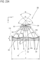
- a boundary position between the central region 532 and the peripheral region 534 is defined by a circle with a radius of 4 to 6 mm (e.g., a radius of about 5 mm) centered on the optical axis Ax.
- the light-shielding sheet 550 is arranged to define respective shapes of the plurality of light source images formed by the plurality of condenser lens portions 542s.
- FIG. 29 is a detailed view of portion V of FIG. 25 .
- the low beam light distribution pattern PL20 is formed as a combined light distribution pattern of two large and small light distribution patterns PLA and PLB.
- a diffusion area is formed by the light distribution pattern PLA, and a high-intensity area HZ is formed near the elbow point E by the light distribution pattern PLB.
- the plurality of total reflection prism elements 532s which allow light emitted from the light-emitting element 522 to be incident and then totally reflected toward the front of the lamp, are formed in a state of being aligned in a concentric circular form centered on the optical axis Ax on the rear surface 532b of the peripheral region 534 located around the central region 532 centered on the optical axis Ax extending in the front-rear direction of the lamp. Therefore, the light emitted from the light-emitting element 522 can be used as forward-radiated light over a wide area while suppressing the depth dimension of the vehicle light 510.
- a light distribution pattern with reduced light distribution unevenness can be formed while reducing the depth dimension.
- the light-shielding sheet 550 including the plurality of light-transmitting portions 550a and 550b for defining the respective outer shapes of the plurality of light source images is arranged between the rear lens array 542 and the front lens array 544 constituting the microlens array 540, allowing the light distribution patterns PLA and PLB corresponding to the respective sizes and outer shapes of the plurality of light-transmitting portions 550a and 550b to be formed, thereby enabling the low beam light distribution pattern PL20 to be formed with an arbitrary light distribution.
- the light source of the lamp unit 510 since the light source of the lamp unit 510 includes the light-emitting element 522 arranged with the light-emitting surface 522a facing toward the front of the lamp, it becomes possible to easily form the low beam light distribution pattern PL20 having the stepped cutoff lines CL21 and CL22 by radiated light from the vehicle lamp 510.
- the rear surface 532b of the central region 532 of the lens 530 of the lamp unit 320 has been described as being formed in a Fresnel lens shape.
- Other configurations e.g., a configuration formed with a single convex lens surface
- the collimator lens 530 has been described as being configured as an injection-molded product.
- Other configurations e.g., those configured as compression-molded products
- the light-shielding sheet 550 has been described as a light-shielding plate with the plurality of light-transmitting portions 550a and 550b formed as the plurality of opening portions.
- Alternatives can also be adopted, such as a transparent sheet on which a light-shielding process has been applied to a surface of a region surrounding the plurality of light-transmitting portions 550a and 550b, a light-shielding film on which a light-shielding process has been applied to a region surrounding the plurality of light-transmitting portions 550a and 550b on the front surface of the rear lens array 542 or the rear surface of the front lens array 544, or the like.
- the plurality of light-transmitting portions 550a and 550b formed in the light-shielding sheet 550 have been described as being arranged in a single vertical row, alternating in the left-right direction.
- a configuration in which a plurality of types of light-transmitting portions are formed can also be adopted as an alternative arrangement.
- the formation of the low beam light distribution pattern PL20 as the necessary light distribution pattern has been described.
- a configuration where a light distribution pattern (e.g., a light distribution pattern for road drawing) is formed can also be adopted.
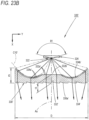
- the basic configuration of the vehicle lamp 610 according to the present modified example is similar to that of the above embodiment.
- the configurations of a collimator lens 630 and a microlens array 640 are partially different from those of the above embodiment.
- the collimator lens 630 of the present modified example has a plurality of condenser lens portions 630s formed on its front surface 630a and is thus configured to perform a function as the rear lens array 542 of the microlens array 540 of the above embodiment.
- the plurality of condenser lens portions 630s are all convex curved fish-eye lenses and are assigned to a plurality of segments divided into a shape of vertical and horizontal grids with the same size as each of the plurality of condenser lens portions 542s formed on the rear lens array 542 of the microlens array 540 of the above embodiment, respectively.
- the microlens array 640 of the present modified example is configured to perform the function as the front lens array 544 in the microlens array 540 of the above embodiment. That is, the microlens array 640 includes the plurality of projection lens portions 640s2 formed on the front surface 640a and the plurality of condenser lens portions 640s1 formed on the rear surface 640b. The plurality of condenser lens portions 640s1 and the plurality of projection lens portions 640s2 are assigned to each of a plurality of segments divided into a shape of vertical and horizontal grids with the same size as each of the plurality of condenser lens portions 630s formed on the front surface 630a of the collimator lens 630.
- the microlens array 640 has an outer peripheral edge region 640c formed in a flat plate shape, and is formed to become thicker toward the rear side of the lamp.
- the vehicle lamp 610 In the vehicle lamp 610 according to the present modified example, light emitted from the light-emitting element 522 is allowed to be incident on the collimator lens 630 to become parallel light, and then condensed by the plurality of condenser lens portions 630s formed on the front surface 630a and the plurality of condenser lens portions 640s1 formed on the rear surface 640b of the microlens array 640, and each of the plurality of light source images formed in this manner is projected by the plurality of projection lens portions 640s2 formed on the front surface 640a of the microlens array 640. Therefore, the effects similar to those of the above embodiment can be achieved.
- the collimator lens 630 of the present modified example has the configuration where the collimator lens 530 and the rear lens array 542 of the microlens array 540 of the above embodiment are integrally formed, the depth dimension of the vehicle lamp 610 can be further reduced, and the cost of the vehicle lamp 610 can be reduced by reducing the number of components.
- FIG. 35 is a view similar to FIG. 27 , showing a vehicle lamp 710 according to the present modified example.
- the basic configuration of the vehicle lamp 710 according to the present modified example is similar to that of the first modified example. Unlike the vehicle lamp 610 according to the first modified example, the light-shielding sheet 550 is not provided, and the configuration of a microlens array 740 is partially different from that of the first modified example.
- the microlens array 740 of the present modified example also includes a plurality of condenser lens portions 740s1 formed on a rear surface 740b and a plurality of projection lens portions 740s2 formed on a front surface 740a.
- the plurality of projection lens portions 740s2 are formed such that the farther they are from the optical axis Ax of the collimator lens 630, the greater the curvature of the horizontal cross-sectional shape of the convex curved surface constituting their surface shape.
- the curvature thereof is set to a substantially constant value.
- the focal length of the plurality of projection lens portions 740s2 within the vertical plane has a substantially constant value, and the focal length within the horizontal plane becomes shorter as they are positioned farther from the optical axis Ax.
- the light emitted from the microlens array 740 becomes light that expands widely in the left-right direction in the projection lens portion 740s2 located close to the optical axis Ax, and becomes light that expands narrowly in the left-right direction in the projection lens portion 740s2 located farther from the optical axis Ax.
- the light distribution pattern shown in FIG. 36 is an additional light distribution pattern PA that is additionally formed for the low beam light distribution pattern PL20 when forming a high beam light distribution pattern PH20.
- appropriately adjusting the value of the focal length for each of the plurality of projection lens portions 740s2 can increase the degree of freedom of the light distribution of the additional light distribution pattern PA formed as a combined light distribution pattern of a plurality of light distribution patterns.
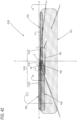
- a vehicle lamp 810 is a headlamp arranged at a front end portion of a vehicle, and includes a lamp unit 820 and 320 incorporated in a lamp chamber formed by a lamp body 812 and a transparent light-transmitting cover 814 attached to a front end opening portion thereof.
- the vehicle lamp 810 is configured to form a low beam light distribution pattern (which will be described below) by radiated light from the lamp unit 820.
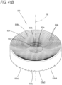
- the plurality of total reflection prism elements 834s formed on the rear surface 834b of the peripheral region 834 form an annular concave curved surface C30 (a cross-sectional shape is indicated by a two-dot chain line in the drawing) centered on the optical axis Ax as an envelope surface.
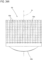
- the emission region 830al is divided into a shape of vertical and horizontal grids, each of which is horizontally long (e.g., about 2 ⁇ 4 mm), with a convex curved lens element 830s1 assigned to each grid.
- Each lens element 830s1 is configured to emit light from the light-emitting element 822, arriving as parallel light from the rear surfaces 832b and 834b of the lens 830, toward the front of the lamp while deflecting the light downward and then diffusing the deflected light in the left-right direction.
- the central region 832 has a substantially constant thickness of about 3 to 4 mm
- the peripheral region 834 has a thinner thickness than the central region 832 in a middle portion thereof and a thicker thickness of about 5 to 6 mm in an outer peripheral edge portion.
- FIG. 42 is a perspective view showing a low beam light distribution pattern PL30 formed on a virtual vertical screen placed 25 m ahead of the lamp by radiated light from the vehicle lamp 810.
- the low beam light distribution pattern PL30 is a low beam light distribution pattern of left light distribution, and an upper end portion thereof is formed with a stepped cutoff line CL30.
- the stepped cutoff line CL30 has a shape in which a lower cutoff line CL31 and an upper cutoff line CL32, offset vertically and extending horizontally, are connected via a slope portion CL33.
- the stepped cutoff line CL30 is formed such that the lower cutoff line CL31 is positioned on the opposite lane side with respect to a V-V line, which is a vertical line passing through an H-V vanishing point in the forward-facing direction of the lamp, and the slope portion CL33 and the upper cutoff line CL32 are positioned on the own lane side.
- the upper cutoff line CL32 is positioned slightly above a line H-H, which is a horizontal line passing through H-V
- an elbow point E which is an intersection of the lower cutoff line CL31 and the slope portion CL33, is located about 0.5 to 0.6° below H-V, and the slope portion CL33 extends obliquely in the upper left direction from the elbow point E at an inclination angle of 15° with respect to the horizontal direction.
- a high-intensity region HZ is formed near the lower left of the elbow point E.
- the low beam light distribution pattern PL30 is formed as a combined light distribution pattern in which five light distribution patterns P31, P32, P33, P34, and P35 are superimposed.
- Such a light distribution pattern P32 is due to the fact that an opening angle of the light-emitting surface 822a of the light-emitting element 822 from the outer peripheral edge portion in the outer periphery-side region of the peripheral region 834 becomes small, and therefore, the light distribution pattern formed by the light emitted from the emission region 830a2 located on the front side of the lamp is likely to be small and bright.
- the light distribution pattern P33 is a light distribution pattern formed by light emitted from the emission region 830a3 on the front surface 830a of the lens 830, and is formed as a small and bright light distribution pattern extending obliquely upward to the left with a narrow vertical width in the vicinity below the H-V
- the light distribution pattern P33 is designed to form the slope portion CL33 and a right end portion of the upper cutoff line CL32 of the low beam light distribution pattern PL30 by its upper end edge. The formation process of the light distribution pattern P33 will be described below.
- the light distribution pattern P34 is a light distribution pattern formed by light emitted from the emission region 830a4 on the front surface 830a of the lens 50, and is formed as a horizontally long bright light distribution pattern expanding leftward from the vicinity of the left of the V-V line with a narrow vertical width substantially along the H-H line.
- the light distribution pattern P34 is designed to form the upper cutoff line CL32 of the low beam light distribution pattern PL30 by its upper end edge. In this case, the light distribution pattern P34 is formed so that a right end portion thereof smoothly connects to and overlaps the light distribution pattern P33.
- the formation of such a light distribution pattern P34 is due to the fact that an opening angle of the light-emitting surface 822a of the light-emitting element 822 from the outer peripheral edge portion in the outer periphery-side region of the peripheral region 834 becomes small, and therefore, the light distribution pattern formed by the light emitted from the emission region 830a4 located on the front side of the lamp is likely to be small and bright.
- the light distribution pattern P35 is a light distribution pattern formed by light emitted from the emission region 830a5 on the front surface 830a of the lens 830 and is formed as a horizontally long, relatively bright light distribution pattern expanding leftward from the vicinity of the left side of the V-V line with a relatively narrow vertical width, spanning both the light distribution pattern P34 and the light distribution pattern P31, with its right end portion overlapping the light distribution pattern P33.
- the light distribution pattern P31 is formed as a horizontally long light distribution pattern widely expanding in the left-right direction centered on the V-V line with a relatively large vertical width, and a position of its upper end edge substantially coincides with the lower cutoff line CL31.
- An upper end portion of the light distribution pattern P31 is formed with a horizontally long high-intensity area HZ1 centered on the V-V line, and a position of its upper end edge substantially coincides with the lower cutoff line CL31.
- the light distribution pattern P31 is shown as a combined light distribution pattern of three light distribution patterns P31A, P31B, and P31C of different sizes.
- the largest light distribution pattern P31A is a light distribution pattern formed by light emitted from the plurality of lens elements 830s1 located in a lower region of the emission region 830al
- the smallest light distribution pattern P31C is a light distribution pattern formed by light emitted from the plurality of lens elements 830s1 located in an upper region of the emission region 830al
- the middle-sized light distribution pattern P31B is a light distribution pattern formed by light emitted from the plurality of lens elements 830s1 located in an middle region in the vertical direction of the emission region 830al.
- the three light distribution patterns P31A to P31C have their upper end edges substantially aligned. This is because, as a configuration of each of the plurality of lens elements 830s1, the inclination angle with respect to the vertical plane orthogonal to the optical axis Ax is set to a larger value for the lens element 830s1 located closer to the lower end edge of the emission region 830al.
- the light distribution pattern P31o is shown as a combined light distribution pattern of three light distribution patterns P31oA, P31oB, and P31oC of different sizes, corresponding to the light distribution pattern P31.
- a light distribution pattern P31' indicated by the two-dot chain line in FIG. 43B is a light distribution pattern formed when, as a configuration of each of the plurality of lens elements 830s1, the inclination angle with respect to the vertical plane orthogonal to the optical axis Ax is unified to the inclination angle of the lens element 830s1 located at the lower end edge of the emission region 830al.
- the three light distribution patterns P31A' to P31C' are formed by parallelly translating the three light distribution patterns P31oA to P3loC downward in parallel by the same angle ⁇ a'.
- a light distribution pattern P33o indicated by a two-dot chain line in FIG. 44 is a light distribution pattern formed if the lens element 830s3 is not present in the emission region 830a3, and is formed to extend obliquely upward to the left in the vicinity below the slope portion CL33.
- the light distribution pattern P33o is formed with an upper end edge as a clear light-dark boundary line. This is because the light-emitting element 822 is arranged with the lower end edge of the light-emitting surface 822a positioned on the optical axis Ax of the lens 830.
- the lens element 830s3 Since the lens element 830s3 is formed in the emission region 830a3, the light distribution pattern P33o changes like the light distribution pattern P33. This is because the lens element 830s3 forms the free-form curved surface whose curvature of the convex curved surface gradually changes from the right half 830s3A to the left half 830s3B, thereby slightly deflecting upward the parallel light arriving at the front surface 830a of the lens 830 and then gradually changing the emission direction from the right half 830s3A to the left half 830s3B.
- the emission region 830a3 is configured by the single lens element 830s3 and has no steps on its surface, a light pool that causes glare is not unintentionally formed in a space above the slope portion CL33 as part of the light distribution pattern P33.
- the vehicle lamp 810 is configured to form the low beam light distribution pattern PL30 having the stepped cutoff line CL30 by radiating light emitted from the light-emitting element 822 (light sources) of the lamp unit 820 toward the front of the lamp through the lens 830.
- the lens 830 is configured such that its front surface 830a is divided into five emission regions 830al, 830a2, 830a3, 830a4, 830a5, and the respective emission regions are formed with the plurality of lens elements 830s1, 830s2, 830s3, 830s4, 830s5 to control the emission of light from the light-emitting elements 822, arriving as parallel light from the rear surfaces 832b and 834b of the lens 830, resulting in an enhanced degree of freedom of light distribution control.
- the plurality of lens elements 830s1 constituting the emission region 830al located in the upper half of the front surface 830a are formed in a state of being divided into a shape of vertical and horizontal grids, it becomes possible to easily form the light distribution pattern P31 with an arbitrary light distribution by appropriately adjusting the directions of the plurality of lens elements 830s1.
- the plurality of lens elements 830s1 have the inclination angles with respect to the vertical plane orthogonal to the optical axis Ax set to a larger value for the lens element located closer to the lower end edge of the emission region 830al, the positions of the upper end edges of the plurality of light distribution patterns (see three light distribution patterns P31A, P31B, and P31C shown in FIG.
- the upper end edge of the light distribution pattern P31 formed as a combined light distribution pattern of the plurality of light distribution patterns can be set to follow the lower cutoff line CL31 of the low beam light distribution pattern PL30.
- the low beam light distribution pattern PL30 having the clear stepped cutoff line CL30 can be formed.
- the plurality of lens elements 830s1 constituting the entire area of the emission region 830al have been described as having the inclination angles with respect to the vertical plane orthogonal to the optical axis Ax set to a larger value for the lens element located closer to the lower end edge of the emission region 830al.
- a configuration can also be adopted in which such a setting is made for the plurality of lens elements 830s1 constituting a part of the emission region 830al (for example, the central region in the left-right direction of the or upper region).
- the emission region 830a5 a configuration can also be adopted in which the plurality of lens elements 830s5 have vertical inclination angles set to different values from each other among the lens elements 830s5 constituting vertical rows divided into a shape of vertical and horizontal grids.
- the light-emitting surface 822a of the light-emitting element 822 has been described as having an outer shape of about 1 ⁇ 1 mm. A light-emitting surface with other shapes can also be used.
- the rear surface 832b of the central region 832 of the lens 830 of the lamp unit 820 has been described as being formed in a Fresnel lens shape.
- Other configurations e.g., a configuration formed with a single convex lens surface
- the lens 830 of the lamp unit 820 has been described as having a circular outer shape when viewed from the front of the lamp.
- a configuration having other outer shapes can also be adopted.
- FIG. 45 is a view similar to FIG. 39 , showing a lamp unit 920 of the vehicle lamp according to the present modified example.
- FIG. 46A is a view similar to FIG. 41A , showing a lens 930 of the lamp unit 920.
- FIG. 46B is a view similar to FIG. 41B , showing the lens 930 of the lamp unit 920.
- the basic configuration of the lamp unit 920 of the present modified example is similar to that of the above embodiment, and the configuration of a front surface 930a of the lens 930 is partially different from that of the above embodiment.
- each of the plurality of lens elements 930s1 is formed with the same width in the left-right direction as each of the plurality of lens elements 830s1 of the above embodiment, and the vertical inclination angle thereof is set to a different value depending on the vertical portion of the lens element 930s1.
- each of the plurality of lens elements 930s1 is formed to extend at an incline toward the front side of the lamp from its upper end edge toward its lower end edge, and in this case, the inclination angle with respect to the vertical plane orthogonal to the optical axis Ax is set to a larger value for a portion of the lens element 930s1 located closer to the lower end edge of the emission region 930al.
- the curvature in the left-right direction of each of the plurality of lens elements 930s1 is set to a larger value for a portion of the lens element 930s1 located closer to the lower end edge of the emission region 930al.
- a light distribution pattern (i.e., light distribution pattern P31 shown in FIG. 43A ) similar to that of the above embodiment is formed by light emitted from the emission region 930al on the front surface 930a of the lens 930.
- the stepped cutoff line CL30 of the low beam light distribution pattern PL30 can be made clearer.
- the front surface 930a of the lens 930 can be made a simpler design compared to the above embodiment, thereby enhancing the appearance of the lens 930.
- the emission region 930al has a surface shape inclined toward the rear as shown in FIG. 45 .
- the plurality of total reflection prism elements 834s form the annular concave curved surface C30 centered on the optical axis Ax as an envelope surface, preventing the thickness of the lens 930 from becoming excessively thin at its upper end portion.
- the plurality of lens elements 930s1 constituting the entire area of the emission region 930al have been described as having the inclination angles with respect to the vertical plane orthogonal to the optical axis Ax set to a larger value for a portion of the lens element located closer to the lower end edge of the emission region 930al.
- a configuration can also be adopted in which such a setting is made for the plurality of lens elements 930s1 constituting a part of the emission region 930al (for example, the central region in the left-right direction).
- a configuration can also be adopted in which the plurality of lens elements 830s5 constituting vertical rows divided into a shape of vertical and horizontal grids are continuously formed.
- the basic configuration of the lens 1230 of the present modified example is similar to that of the above embodiment, and the configuration of an emission region 1230al on a front surface 1230a is partially different from that of the above embodiment.
- the emission region 1230al on the front surface 1230a of the lens 1230 of the present modified example is different from that of the above embodiment, in terms of a configuration of a plurality of lens elements 1230s1B constituting an upper region 1230alB.
- each of the plurality of lens elements 1230s1B is configured to emit light from the light-emitting element 822, arriving as parallel light from the rear surfaces 832b and 834b of the lens 1230, toward the front of the lamp while slightly deflecting the light downward and then more widely diffusing the deflected light in the left direction than in the right direction.
- the configuration of the plurality of lens elements 1230s1A constituting the general area 1230alA other than the upper region 1230alB in the emission region 1230al is similar to that of the above embodiment.
- FIG. 48 is a perspective view showing a low beam light distribution pattern PL30-2 formed on the virtual vertical screen by radiated light from the vehicle lamp according to the present modified example.
- the low beam light distribution pattern PL30-2 is also formed as a combined light distribution pattern in which five light distribution patterns P31-2, P32, P33, P34, and P35 are superimposed, as with the low beam light distribution pattern PL30 of the above embodiment.
- the formation position of the high-intensity area HZ1-2 in the light distribution pattern P31-2 is displaced further to the left than the high-intensity area HZ1 in the light distribution pattern P31 of the above embodiment. This is because the plurality of lens elements 1230s1B constituting the upper region 1230alB of the emission region 1230al are configured to emit light from the light-emitting element 822 toward the front of the lamp while more widely diffusing the light in the left direction than in the right direction.
- the high-intensity area HZ-2 in the low beam light distribution pattern PL30-2 can be formed closer to the shoulder on the own lane side than in the above embodiment, thereby achieving a light distribution more suitable for vehicle traveling.
Landscapes
- Engineering & Computer Science (AREA)
- General Engineering & Computer Science (AREA)
- Physics & Mathematics (AREA)
- Microelectronics & Electronic Packaging (AREA)
- Optics & Photonics (AREA)
- Non-Portable Lighting Devices Or Systems Thereof (AREA)
Applications Claiming Priority (5)
| Application Number | Priority Date | Filing Date | Title |
|---|---|---|---|
| JP2022093905A JP7788351B2 (ja) | 2022-06-09 | 2022-06-09 | 車両用灯具 |
| JP2022093906A JP7788352B2 (ja) | 2022-06-09 | 2022-06-09 | 車両用灯具 |
| JP2022093904A JP7788350B2 (ja) | 2022-06-09 | 2022-06-09 | 車両用灯具 |
| JP2022093903A JP7732946B2 (ja) | 2022-06-09 | 2022-06-09 | 車両用灯具 |
| PCT/JP2023/019301 WO2023238667A1 (fr) | 2022-06-09 | 2023-05-24 | Lampe de véhicule |
Publications (2)
| Publication Number | Publication Date |
|---|---|
| EP4538593A1 true EP4538593A1 (fr) | 2025-04-16 |
| EP4538593A4 EP4538593A4 (fr) | 2025-10-29 |
Family
ID=89118147
Family Applications (1)
| Application Number | Title | Priority Date | Filing Date |
|---|---|---|---|
| EP23819650.5A Pending EP4538593A4 (fr) | 2022-06-09 | 2023-05-24 | Lampe de véhicule |
Country Status (4)
| Country | Link |
|---|---|
| US (1) | US20250361997A1 (fr) |
| EP (1) | EP4538593A4 (fr) |
| CN (1) | CN119343562A (fr) |
| WO (1) | WO2023238667A1 (fr) |
Families Citing this family (1)
| Publication number | Priority date | Publication date | Assignee | Title |
|---|---|---|---|---|
| DE102024124503A1 (de) * | 2024-08-28 | 2026-03-05 | HELLA GmbH & Co. KGaA | Beleuchtungsvorrichtung für ein Kraftfahrzeug |
Family Cites Families (16)
| Publication number | Priority date | Publication date | Assignee | Title |
|---|---|---|---|---|
| JP2009187859A (ja) | 2008-02-08 | 2009-08-20 | Koito Mfg Co Ltd | 車両用照明灯具 |
| JP5649047B2 (ja) * | 2010-09-29 | 2015-01-07 | シチズン電子株式会社 | レンズ部材及び光学ユニット |
| JP5784366B2 (ja) * | 2011-05-27 | 2015-09-24 | ミネベア株式会社 | 照明装置 |
| WO2013024836A1 (fr) * | 2011-08-12 | 2013-02-21 | シチズン電子株式会社 | Elément de lentille et dispositif électroluminescent utilisant celui-ci |
| JP6600987B2 (ja) * | 2015-05-21 | 2019-11-06 | 市光工業株式会社 | 車両用灯具 |
| AT517887B1 (de) * | 2015-10-23 | 2018-06-15 | Zkw Group Gmbh | Mikroprojektions-Lichtmodul für Fahrzeugscheinwerfer |
| JP2020072055A (ja) * | 2018-11-02 | 2020-05-07 | 株式会社小糸製作所 | 車両用灯具 |
| JP2020061231A (ja) | 2018-10-05 | 2020-04-16 | 株式会社小糸製作所 | 車両用灯具 |
| WO2020071413A1 (fr) * | 2018-10-05 | 2020-04-09 | 株式会社小糸製作所 | Phare de véhicule |
| EP3879313A1 (fr) * | 2020-03-11 | 2021-09-15 | ZKW Group GmbH | Système de microlentilles pour un phare de véhicule automobile |
| JP7474116B2 (ja) * | 2020-05-29 | 2024-04-24 | 株式会社小糸製作所 | 光学ユニット、及びそれを備えた車両用灯具 |
| US11236870B2 (en) * | 2020-06-25 | 2022-02-01 | Lumileds Llc | Illuminator having combination refractive and TIR lens |
| JP2022093905A (ja) | 2020-12-14 | 2022-06-24 | 日本電産株式会社 | 振動モータ |
| JP7610964B2 (ja) | 2020-12-14 | 2025-01-09 | 大和ハウス工業株式会社 | 座屈拘束ブレース |
| JP7031100B1 (ja) | 2020-12-14 | 2022-03-08 | 株式会社Abri | リチウム二次電池用ゲル電解質、リチウム二次電池およびリチウム二次電池の製造方法 |
| JP7499167B2 (ja) | 2020-12-14 | 2024-06-13 | 株式会社栗本鐵工所 | 貫通ダクト構造 |
-
2023
- 2023-05-24 US US18/872,648 patent/US20250361997A1/en active Pending
- 2023-05-24 CN CN202380045822.9A patent/CN119343562A/zh active Pending
- 2023-05-24 WO PCT/JP2023/019301 patent/WO2023238667A1/fr not_active Ceased
- 2023-05-24 EP EP23819650.5A patent/EP4538593A4/fr active Pending
Also Published As
| Publication number | Publication date |
|---|---|
| WO2023238667A1 (fr) | 2023-12-14 |
| EP4538593A4 (fr) | 2025-10-29 |
| CN119343562A (zh) | 2025-01-21 |
| US20250361997A1 (en) | 2025-11-27 |
Similar Documents
| Publication | Publication Date | Title |
|---|---|---|
| US7156544B2 (en) | Vehicle headlamp | |
| CN112805500B (zh) | 车辆用灯具 | |
| EP2093480B1 (fr) | Dispositif d'éclairage de véhicule | |
| JP4068387B2 (ja) | 光源ユニット | |
| US7108412B2 (en) | Headlamp for vehicle | |
| US7134775B2 (en) | Vehicular headlamp and light-emitting module therefor | |
| US7513654B2 (en) | Lighting device for vehicle | |
| JP4080780B2 (ja) | 光源ユニット | |
| US20170276310A1 (en) | Vehicle lamp and vehicle having the same | |
| JP5636756B2 (ja) | 車両用灯具ユニット | |
| US20070236950A1 (en) | Headlight assembly having strongly trained cut-off | |
| GB2394036A (en) | Headlamp for vehicle | |
| JP7503071B2 (ja) | 車両用のマイクロレンズアレイおよびそれを用いた車両用灯具 | |
| JP7506809B2 (ja) | 車両用灯具 | |
| CN109073179B (zh) | 车辆用灯具 | |
| JP6967396B2 (ja) | 車両用灯具 | |
| JP2020061231A (ja) | 車両用灯具 | |
| CN102313227B (zh) | 车辆用照明灯具 | |
| US7201499B2 (en) | Vehicle lamp unit | |
| US10514144B2 (en) | Vehicle lamp | |
| EP4538593A1 (fr) | Lampe de véhicule | |
| JP5692520B2 (ja) | 灯具ユニット | |
| JP7467500B2 (ja) | 車両用前照灯 | |
| JP4865060B2 (ja) | 車両用灯具 | |
| JP7732946B2 (ja) | 車両用灯具 |
Legal Events
| Date | Code | Title | Description |
|---|---|---|---|
| STAA | Information on the status of an ep patent application or granted ep patent |
Free format text: STATUS: THE INTERNATIONAL PUBLICATION HAS BEEN MADE |
|
| PUAI | Public reference made under article 153(3) epc to a published international application that has entered the european phase |
Free format text: ORIGINAL CODE: 0009012 |
|
| STAA | Information on the status of an ep patent application or granted ep patent |
Free format text: STATUS: REQUEST FOR EXAMINATION WAS MADE |
|
| 17P | Request for examination filed |
Effective date: 20241209 |
|
| AK | Designated contracting states |
Kind code of ref document: A1 Designated state(s): AL AT BE BG CH CY CZ DE DK EE ES FI FR GB GR HR HU IE IS IT LI LT LU LV MC ME MK MT NL NO PL PT RO RS SE SI SK SM TR |
|
| DAV | Request for validation of the european patent (deleted) | ||
| DAX | Request for extension of the european patent (deleted) | ||
| A4 | Supplementary search report drawn up and despatched |
Effective date: 20250929 |
|
| RIC1 | Information provided on ipc code assigned before grant |
Ipc: F21Y 115/10 20160101AFI20250923BHEP Ipc: F21V 5/04 20060101ALI20250923BHEP Ipc: F21S 41/143 20180101ALI20250923BHEP Ipc: F21S 41/25 20180101ALI20250923BHEP Ipc: F21S 41/255 20180101ALI20250923BHEP Ipc: F21S 41/43 20180101ALI20250923BHEP Ipc: F21W 102/13 20180101ALI20250923BHEP Ipc: F21W 102/17 20180101ALI20250923BHEP Ipc: F21S 41/32 20180101ALI20250923BHEP |