EP4538596A1 - Procédé de retrait de plaque de capuchon interne arrière et outillage pour chambre de combustion avec tubes de micromélangeur - Google Patents
Procédé de retrait de plaque de capuchon interne arrière et outillage pour chambre de combustion avec tubes de micromélangeur Download PDFInfo
- Publication number
- EP4538596A1 EP4538596A1 EP24199184.3A EP24199184A EP4538596A1 EP 4538596 A1 EP4538596 A1 EP 4538596A1 EP 24199184 A EP24199184 A EP 24199184A EP 4538596 A1 EP4538596 A1 EP 4538596A1
- Authority
- EP
- European Patent Office
- Prior art keywords
- aft plate
- aft
- removal tool
- plate
- threaded rod
- Prior art date
- Legal status (The legal status is an assumption and is not a legal conclusion. Google has not performed a legal analysis and makes no representation as to the accuracy of the status listed.)
- Pending
Links
Images


Classifications
-
- B—PERFORMING OPERATIONS; TRANSPORTING
- B25—HAND TOOLS; PORTABLE POWER-DRIVEN TOOLS; MANIPULATORS
- B25B—TOOLS OR BENCH DEVICES NOT OTHERWISE PROVIDED FOR, FOR FASTENING, CONNECTING, DISENGAGING, OR HOLDING
- B25B27/00—Hand tools, specially adapted for fitting together or separating parts or objects whether or not involving some deformation, not otherwise provided for
- B25B27/14—Hand tools, specially adapted for fitting together or separating parts or objects whether or not involving some deformation, not otherwise provided for for assembling objects other than by press fit or detaching same
-
- B—PERFORMING OPERATIONS; TRANSPORTING
- B25—HAND TOOLS; PORTABLE POWER-DRIVEN TOOLS; MANIPULATORS
- B25B—TOOLS OR BENCH DEVICES NOT OTHERWISE PROVIDED FOR, FOR FASTENING, CONNECTING, DISENGAGING, OR HOLDING
- B25B27/00—Hand tools, specially adapted for fitting together or separating parts or objects whether or not involving some deformation, not otherwise provided for
- B25B27/02—Hand tools, specially adapted for fitting together or separating parts or objects whether or not involving some deformation, not otherwise provided for for connecting objects by press fit or detaching same
- B25B27/023—Hand tools, specially adapted for fitting together or separating parts or objects whether or not involving some deformation, not otherwise provided for for connecting objects by press fit or detaching same using screws
-
- B—PERFORMING OPERATIONS; TRANSPORTING
- B25—HAND TOOLS; PORTABLE POWER-DRIVEN TOOLS; MANIPULATORS
- B25B—TOOLS OR BENCH DEVICES NOT OTHERWISE PROVIDED FOR, FOR FASTENING, CONNECTING, DISENGAGING, OR HOLDING
- B25B27/00—Hand tools, specially adapted for fitting together or separating parts or objects whether or not involving some deformation, not otherwise provided for
- B25B27/02—Hand tools, specially adapted for fitting together or separating parts or objects whether or not involving some deformation, not otherwise provided for for connecting objects by press fit or detaching same
- B25B27/06—Hand tools, specially adapted for fitting together or separating parts or objects whether or not involving some deformation, not otherwise provided for for connecting objects by press fit or detaching same inserting or withdrawing sleeves or bearing races
- B25B27/062—Hand tools, specially adapted for fitting together or separating parts or objects whether or not involving some deformation, not otherwise provided for for connecting objects by press fit or detaching same inserting or withdrawing sleeves or bearing races using screws
-
- F—MECHANICAL ENGINEERING; LIGHTING; HEATING; WEAPONS; BLASTING
- F02—COMBUSTION ENGINES; HOT-GAS OR COMBUSTION-PRODUCT ENGINE PLANTS
- F02C—GAS-TURBINE PLANTS; AIR INTAKES FOR JET-PROPULSION PLANTS; CONTROLLING FUEL SUPPLY IN AIR-BREATHING JET-PROPULSION PLANTS
- F02C7/00—Features, components parts, details or accessories, not provided for in, or of interest apart form groups F02C1/00 - F02C6/00; Air intakes for jet-propulsion plants
- F02C7/22—Fuel supply systems
-
- F—MECHANICAL ENGINEERING; LIGHTING; HEATING; WEAPONS; BLASTING
- F23—COMBUSTION APPARATUS; COMBUSTION PROCESSES
- F23R—GENERATING COMBUSTION PRODUCTS OF HIGH PRESSURE OR HIGH VELOCITY, e.g. GAS-TURBINE COMBUSTION CHAMBERS
- F23R3/00—Continuous combustion chambers using liquid or gaseous fuel
- F23R3/42—Continuous combustion chambers using liquid or gaseous fuel characterised by the arrangement or form of the flame tubes or combustion chambers
-
- F—MECHANICAL ENGINEERING; LIGHTING; HEATING; WEAPONS; BLASTING
- F23—COMBUSTION APPARATUS; COMBUSTION PROCESSES
- F23R—GENERATING COMBUSTION PRODUCTS OF HIGH PRESSURE OR HIGH VELOCITY, e.g. GAS-TURBINE COMBUSTION CHAMBERS
- F23R3/00—Continuous combustion chambers using liquid or gaseous fuel
- F23R3/42—Continuous combustion chambers using liquid or gaseous fuel characterised by the arrangement or form of the flame tubes or combustion chambers
- F23R3/46—Combustion chambers comprising an annular arrangement of several essentially tubular flame tubes within a common annular casing or within individual casings
-
- F—MECHANICAL ENGINEERING; LIGHTING; HEATING; WEAPONS; BLASTING
- F23—COMBUSTION APPARATUS; COMBUSTION PROCESSES
- F23R—GENERATING COMBUSTION PRODUCTS OF HIGH PRESSURE OR HIGH VELOCITY, e.g. GAS-TURBINE COMBUSTION CHAMBERS
- F23R3/00—Continuous combustion chambers using liquid or gaseous fuel
- F23R3/42—Continuous combustion chambers using liquid or gaseous fuel characterised by the arrangement or form of the flame tubes or combustion chambers
- F23R3/60—Support structures; Attaching or mounting means
-
- F—MECHANICAL ENGINEERING; LIGHTING; HEATING; WEAPONS; BLASTING
- F05—INDEXING SCHEMES RELATING TO ENGINES OR PUMPS IN VARIOUS SUBCLASSES OF CLASSES F01-F04
- F05D—INDEXING SCHEME FOR ASPECTS RELATING TO NON-POSITIVE-DISPLACEMENT MACHINES OR ENGINES, GAS-TURBINES OR JET-PROPULSION PLANTS
- F05D2230/00—Manufacture
- F05D2230/70—Disassembly methods
-
- F—MECHANICAL ENGINEERING; LIGHTING; HEATING; WEAPONS; BLASTING
- F05—INDEXING SCHEMES RELATING TO ENGINES OR PUMPS IN VARIOUS SUBCLASSES OF CLASSES F01-F04
- F05D—INDEXING SCHEME FOR ASPECTS RELATING TO NON-POSITIVE-DISPLACEMENT MACHINES OR ENGINES, GAS-TURBINES OR JET-PROPULSION PLANTS
- F05D2230/00—Manufacture
- F05D2230/80—Repairing, retrofitting or upgrading methods
-
- F—MECHANICAL ENGINEERING; LIGHTING; HEATING; WEAPONS; BLASTING
- F05—INDEXING SCHEMES RELATING TO ENGINES OR PUMPS IN VARIOUS SUBCLASSES OF CLASSES F01-F04
- F05D—INDEXING SCHEME FOR ASPECTS RELATING TO NON-POSITIVE-DISPLACEMENT MACHINES OR ENGINES, GAS-TURBINES OR JET-PROPULSION PLANTS
- F05D2240/00—Components
- F05D2240/35—Combustors or associated equipment
-
- F—MECHANICAL ENGINEERING; LIGHTING; HEATING; WEAPONS; BLASTING
- F23—COMBUSTION APPARATUS; COMBUSTION PROCESSES
- F23R—GENERATING COMBUSTION PRODUCTS OF HIGH PRESSURE OR HIGH VELOCITY, e.g. GAS-TURBINE COMBUSTION CHAMBERS
- F23R2900/00—Special features of, or arrangements for continuous combustion chambers; Combustion processes therefor
- F23R2900/00017—Assembling combustion chamber liners or subparts
-
- F—MECHANICAL ENGINEERING; LIGHTING; HEATING; WEAPONS; BLASTING
- F23—COMBUSTION APPARATUS; COMBUSTION PROCESSES
- F23R—GENERATING COMBUSTION PRODUCTS OF HIGH PRESSURE OR HIGH VELOCITY, e.g. GAS-TURBINE COMBUSTION CHAMBERS
- F23R2900/00—Special features of, or arrangements for continuous combustion chambers; Combustion processes therefor
- F23R2900/00019—Repairing or maintaining combustion chamber liners or subparts
-
- F—MECHANICAL ENGINEERING; LIGHTING; HEATING; WEAPONS; BLASTING
- F23—COMBUSTION APPARATUS; COMBUSTION PROCESSES
- F23R—GENERATING COMBUSTION PRODUCTS OF HIGH PRESSURE OR HIGH VELOCITY, e.g. GAS-TURBINE COMBUSTION CHAMBERS
- F23R3/00—Continuous combustion chambers using liquid or gaseous fuel
- F23R3/28—Continuous combustion chambers using liquid or gaseous fuel characterised by the fuel supply
- F23R3/286—Continuous combustion chambers using liquid or gaseous fuel characterised by the fuel supply having fuel-air premixing devices
Definitions
- the combustors may include one or more bundled tube fuel injectors that extend downstream from an end cover.
- the bundled tube fuel injectors generally include a number of pre-mix or micromixer tubes.
- the micromixer tubes extend generally parallel to one another through the bundled tube fuel injector.
- An outer shroud extends circumferentially around the micromixer tubes and an aft plate extends radially and circumferentially across a downstream end thereof adjacent to a combustion chamber or zone defined within the combustor.
- a tube tip portion of each micromixer tube extends through the aft plate such that an outlet of each tube is downstream from a hot side surface of the aft plate, thus providing for fluid communication into the combustion chamber or zone.
- Fig. 1 shows a schematic diagram of a gas turbine engine 10 as may be described herein.
- the gas turbine engine 10 may include a compressor 15.
- the compressor 15 compresses an incoming flow of air 20.
- the compressor 15 delivers the compressed flow of air 20 to a number of combustor cans 25.
- the combustor cans 25 mix the compressed flow of air 20 with a pressurized flow of fuel 30 and ignite the mixture to create a flow of hot combustion gases 35.
- the gas turbine engine 10 may include any number of combustor cans 25 positioned in a circumferential array and the like.
- the gas turbine engine 10 may use natural gas, various types of syngas, liquid fuels, and/or other types of fuels and blends thereof.
- the gas turbine engine 10 may be any one of a number of different gas turbine engines offered by General Electric Company of Schenectady, New York, including, but not limited to, those such as a 7-series or a 9-series heavy duty gas turbine engine and the like.
- the gas turbine engine 10 may be part of a simple cycle or a combined cycle power generation system or other types of generation systems.
- the gas turbine engine 10 may have different configurations and may use other types of components. Other types of gas turbine engines also may be used herein. Multiple gas turbine engines, other types of turbines, and other types of power generation equipment also may be used herein together.
- the fuel injectors 52 extend downstream from the end cover 58.
- the fuel injector 52 may be fluidly connected to the end cover 58 so as to receive the flow of fuel 30.
- a fluid conduit 60 may provide for fluid communication between the end cover 58 and the fuel injector 52.
- One end of an annular liner 62 such as a combustion liner and/or a transition duct surrounds a downstream end 64 of the fuel injector 52 so as to at least partially define a combustion chamber 66.
- the liner 62 defines a hot gas path 68 for directing the combustion gases 35 from the combustion chamber 66.
- Figs. 7 and 8 show the inner aft plate removal tool 105 in use.
- the inner aft plate removal tool 105 may be inserted within the central passage 86 of the combustor 25.
- the inner aft plate removal tool 105 may be advanced therein until the replaceable tip 150 contacts the aft plate 78.
- the base plate 110 may be attached to the end cover 48 by attaching the mounting bolts 180.
- the threaded rod 140 may be rotated to advance. Specifically, the threaded rod 140 is rotated within the threaded insert 130 of the base plate 110.
- the lower feet 260 and the upper feet 290 may be retracted via the set screw 330.
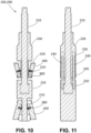
- the outer aft plate removal tool 200 may be inserted within the center passage 86 of the aft plate 78 and the inner cap assembly 94. Once clear of the aft plate 78, the lower feet 260 and the upper feet 290 may be extended.
- the lower feet 260 may be positioned about the downstream plate 74 and the upper feet 290 may be positioned beneath the aft plate 78.
- the upper housing 230 may be rotated and may move upward against the aft plate 78. As the upper housing 230 advances in contact with the aft plate 78, the upper feet 290 may flatten any deformation in the aft plate 78.
Landscapes
- Engineering & Computer Science (AREA)
- Mechanical Engineering (AREA)
- Chemical & Material Sciences (AREA)
- Combustion & Propulsion (AREA)
- General Engineering & Computer Science (AREA)
- Gas Burners (AREA)
Applications Claiming Priority (1)
| Application Number | Priority Date | Filing Date | Title |
|---|---|---|---|
| US18/479,194 US12434362B2 (en) | 2023-10-02 | 2023-10-02 | Aft inner cap plate removal method and tooling for a combustor with micromixer tubes |
Publications (1)
| Publication Number | Publication Date |
|---|---|
| EP4538596A1 true EP4538596A1 (fr) | 2025-04-16 |
Family
ID=92712343
Family Applications (1)
| Application Number | Title | Priority Date | Filing Date |
|---|---|---|---|
| EP24199184.3A Pending EP4538596A1 (fr) | 2023-10-02 | 2024-09-09 | Procédé de retrait de plaque de capuchon interne arrière et outillage pour chambre de combustion avec tubes de micromélangeur |
Country Status (5)
| Country | Link |
|---|---|
| US (2) | US12434362B2 (fr) |
| EP (1) | EP4538596A1 (fr) |
| JP (1) | JP2025062568A (fr) |
| KR (1) | KR20250048519A (fr) |
| CN (1) | CN119748087A (fr) |
Citations (6)
| Publication number | Priority date | Publication date | Assignee | Title |
|---|---|---|---|---|
| US20030217465A1 (en) * | 2002-05-21 | 2003-11-27 | Spx Corporation | Cylinder liner remover and installer |
| US20140338344A1 (en) * | 2013-03-15 | 2014-11-20 | General Electric Company | System Having a Multi-Tube Fuel Nozzle with a Fuel Nozzle Housing |
| US20150059177A1 (en) * | 2013-08-27 | 2015-03-05 | General Electric Company | Method for removing an end cap of a combustor cap assembly |
| US20150167556A1 (en) * | 2013-12-13 | 2015-06-18 | General Electric Company | Method for disassembling a bundled tube fuel injector |
| US20180100654A1 (en) * | 2016-10-10 | 2018-04-12 | General Electric Company | Tool and method for decoupling cross-fire tube assemblies in gas turbine engines |
| US20180363906A1 (en) * | 2017-06-16 | 2018-12-20 | General Electric Company | Cooling of liquid fuel cartridge in gas turbine combustor head end |
Family Cites Families (29)
| Publication number | Priority date | Publication date | Assignee | Title |
|---|---|---|---|---|
| US2310639A (en) * | 1941-02-11 | 1943-02-09 | Jr Charles E Johnson | Bushing tool |
| US2290427A (en) * | 1941-03-14 | 1942-07-21 | Samuel A Harrington | Bearing puller |
| USD294219S (en) * | 1985-04-17 | 1988-02-16 | George Hamatani | Bushing puller |
| US5781977A (en) * | 1995-02-13 | 1998-07-21 | Lawrence I. Wechsler | Ball joint compressor |
| US8528176B2 (en) * | 2008-10-24 | 2013-09-10 | Pratt & Whitney Canada Corp. | Diffuser case removal apparatus and method |
| US8875369B2 (en) * | 2009-12-02 | 2014-11-04 | Darlene Heimmer | Self-aligning plug removal and installation system and method |
| US20110214269A1 (en) * | 2010-03-05 | 2011-09-08 | Min-Chi Yu | Bearing puller |
| US8683670B2 (en) * | 2010-12-20 | 2014-04-01 | Turbine Tooling Solutions Llc | Method for partial disassembly of a bypass turbofan engine |
| US9562687B2 (en) | 2013-02-06 | 2017-02-07 | General Electric Company | Variable volume combustor with an air bypass system |
| US9528703B2 (en) | 2013-09-20 | 2016-12-27 | General Electric Company | Micro-mixer fuel plenum and methods for fuel tube installation |
| US9423134B2 (en) | 2013-12-13 | 2016-08-23 | General Electric Company | Bundled tube fuel injector with a multi-configuration tube tip |
| US9664392B2 (en) * | 2013-12-13 | 2017-05-30 | General Electric Company | Bundled tube fuel injector with outer shroud and outer band connection |
| US9259807B2 (en) | 2013-12-13 | 2016-02-16 | General Electric Company | Method for repairing a bundled tube fuel injector |
| US20150167983A1 (en) | 2013-12-13 | 2015-06-18 | General Electric Company | Bundled tube fuel injector tube tip |
| US9423136B2 (en) * | 2013-12-13 | 2016-08-23 | General Electric Company | Bundled tube fuel injector aft plate retention |
| CN204893838U (zh) * | 2015-06-29 | 2015-12-23 | 珠海保税区摩天宇航空发动机维修有限公司 | 发动机高压涡轮平衡工具分离拆卸液压拔具 |
| US10690059B2 (en) | 2016-09-26 | 2020-06-23 | General Electric Company | Advanced seals with reduced corner leakage |
| US11525578B2 (en) * | 2017-08-16 | 2022-12-13 | General Electric Company | Dynamics-mitigating adapter for bundled tube fuel nozzle |
| US11371706B2 (en) * | 2017-12-18 | 2022-06-28 | General Electric Company | Premixed pilot nozzle for gas turbine combustor |
| US10906164B2 (en) * | 2018-06-22 | 2021-02-02 | Raytheon Technologies Corporation | Immobilizer tool set for bolt installation and method |
| CN110774600B (zh) * | 2019-10-31 | 2021-10-29 | 大族激光科技产业集团股份有限公司 | 用于汽车电动尾门的压入旋转机构以及产品质量检测方法 |
| US10710222B1 (en) * | 2019-11-08 | 2020-07-14 | Peter W. Utecht | Hydraulic cylinder assembly system |
| US11370094B2 (en) * | 2020-03-25 | 2022-06-28 | Globalfoundries U.S. Inc. | Disassembly tool for electrostatic chuck |
| US11326521B2 (en) * | 2020-06-30 | 2022-05-10 | General Electric Company | Methods of igniting liquid fuel in a turbomachine |
| US11383364B2 (en) * | 2020-12-11 | 2022-07-12 | Bosch Automotive Service Solutions Inc. | Puller tool and adapter |
| US11898360B2 (en) * | 2020-12-15 | 2024-02-13 | Jim Petty | Flooring installation assembly |
| US12138758B2 (en) * | 2022-04-20 | 2024-11-12 | Textron Innovations Inc | Wear sleeve removal tool for rotorcraft |
| US12103148B1 (en) * | 2023-10-02 | 2024-10-01 | Ge Infrastructure Technology Llc | Aft inner cap plate removal method and tooling for a combustor with micromixer tubes |
| CN119260656A (zh) * | 2024-10-18 | 2025-01-07 | 中船海洋动力技术服务有限公司 | 一种用于船用低速机气缸套绝缘管拔除的工具 |
-
2023
- 2023-10-02 US US18/479,194 patent/US12434362B2/en active Active
-
2024
- 2024-08-28 CN CN202411191574.1A patent/CN119748087A/zh active Pending
- 2024-09-03 JP JP2024151527A patent/JP2025062568A/ja active Pending
- 2024-09-09 EP EP24199184.3A patent/EP4538596A1/fr active Pending
- 2024-09-25 KR KR1020240129750A patent/KR20250048519A/ko active Pending
-
2025
- 2025-04-10 US US19/175,065 patent/US20250235997A1/en active Pending
Patent Citations (6)
| Publication number | Priority date | Publication date | Assignee | Title |
|---|---|---|---|---|
| US20030217465A1 (en) * | 2002-05-21 | 2003-11-27 | Spx Corporation | Cylinder liner remover and installer |
| US20140338344A1 (en) * | 2013-03-15 | 2014-11-20 | General Electric Company | System Having a Multi-Tube Fuel Nozzle with a Fuel Nozzle Housing |
| US20150059177A1 (en) * | 2013-08-27 | 2015-03-05 | General Electric Company | Method for removing an end cap of a combustor cap assembly |
| US20150167556A1 (en) * | 2013-12-13 | 2015-06-18 | General Electric Company | Method for disassembling a bundled tube fuel injector |
| US20180100654A1 (en) * | 2016-10-10 | 2018-04-12 | General Electric Company | Tool and method for decoupling cross-fire tube assemblies in gas turbine engines |
| US20180363906A1 (en) * | 2017-06-16 | 2018-12-20 | General Electric Company | Cooling of liquid fuel cartridge in gas turbine combustor head end |
Also Published As
| Publication number | Publication date |
|---|---|
| KR20250048519A (ko) | 2025-04-09 |
| US20250235997A1 (en) | 2025-07-24 |
| JP2025062568A (ja) | 2025-04-14 |
| US20250108492A1 (en) | 2025-04-03 |
| CN119748087A (zh) | 2025-04-04 |
| US12434362B2 (en) | 2025-10-07 |
Similar Documents
| Publication | Publication Date | Title |
|---|---|---|
| US9400114B2 (en) | Combustor support assembly for mounting a combustion module of a gas turbine | |
| US10072847B2 (en) | Method for repairing a bundled tube fuel injector | |
| US9664392B2 (en) | Bundled tube fuel injector with outer shroud and outer band connection | |
| US10215413B2 (en) | Bundled tube fuel nozzle with vibration damping | |
| CN110857783B (zh) | 用于涡轮机的燃烧器组件 | |
| EP3312510A1 (fr) | Ensemble chambre de combustion avec écran d'air pour un injecteur de carburant radial | |
| EP4534909A1 (fr) | Procédé de retrait de plaque de capuchon interne arrière et outillage pour chambre de combustion avec tubes de micromélangeur | |
| US20170343216A1 (en) | Fuel Nozzle Assembly with Tube Damping | |
| US20140318139A1 (en) | Premixer assembly for gas turbine combustor | |
| US9157370B2 (en) | Burner assembly | |
| US12434362B2 (en) | Aft inner cap plate removal method and tooling for a combustor with micromixer tubes | |
| EP3961103B1 (fr) | Procédés d'entretien de pointe d'injecteur de carburant | |
| US11802493B2 (en) | Outlet guide vane assembly in gas turbine engine | |
| EP3586061B1 (fr) | Ensemble couvercle d'extrémité pour chambre de combustion | |
| EP3751201A1 (fr) | Procédés d'installation/de retrait de tubes cross-fire et appareil | |
| CN116772238B (zh) | 圆顶-导流器接头冷却布置 | |
| BR102024019748A2 (pt) | Método de remoção da placa da tampa interna da popa e ferramentas para um combustor com tubos micromisturadores |
Legal Events
| Date | Code | Title | Description |
|---|---|---|---|
| PUAI | Public reference made under article 153(3) epc to a published international application that has entered the european phase |
Free format text: ORIGINAL CODE: 0009012 |
|
| STAA | Information on the status of an ep patent application or granted ep patent |
Free format text: STATUS: THE APPLICATION HAS BEEN PUBLISHED |
|
| AK | Designated contracting states |
Kind code of ref document: A1 Designated state(s): AL AT BE BG CH CY CZ DE DK EE ES FI FR GB GR HR HU IE IS IT LI LT LU LV MC ME MK MT NL NO PL PT RO RS SE SI SK SM TR |
|
| RAP3 | Party data changed (applicant data changed or rights of an application transferred) |
Owner name: GE VERNOVA TECHNOLOGY GMBH |
|
| STAA | Information on the status of an ep patent application or granted ep patent |
Free format text: STATUS: REQUEST FOR EXAMINATION WAS MADE |
|
| 17P | Request for examination filed |
Effective date: 20251014 |