EP4538717A2 - Distributeur de liquide a support de collecteur pour canaux de pipette modulaires actionnes independamment - Google Patents
Distributeur de liquide a support de collecteur pour canaux de pipette modulaires actionnes independamment Download PDFInfo
- Publication number
- EP4538717A2 EP4538717A2 EP25160564.8A EP25160564A EP4538717A2 EP 4538717 A2 EP4538717 A2 EP 4538717A2 EP 25160564 A EP25160564 A EP 25160564A EP 4538717 A2 EP4538717 A2 EP 4538717A2
- Authority
- EP
- European Patent Office
- Prior art keywords
- pipette
- channel
- manifold
- channels
- pressure
- Prior art date
- Legal status (The legal status is an assumption and is not a legal conclusion. Google has not performed a legal analysis and makes no representation as to the accuracy of the status listed.)
- Pending
Links
Images















Classifications
-
- B—PERFORMING OPERATIONS; TRANSPORTING
- B01—PHYSICAL OR CHEMICAL PROCESSES OR APPARATUS IN GENERAL
- B01F—MIXING, e.g. DISSOLVING, EMULSIFYING OR DISPERSING
- B01F23/00—Mixing according to the phases to be mixed, e.g. dispersing or emulsifying
- B01F23/20—Mixing gases with liquids
- B01F23/23—Mixing gases with liquids by introducing gases into liquid media, e.g. for producing aerated liquids
- B01F23/232—Mixing gases with liquids by introducing gases into liquid media, e.g. for producing aerated liquids using flow-mixing means for introducing the gases, e.g. baffles
-
- B—PERFORMING OPERATIONS; TRANSPORTING
- B01—PHYSICAL OR CHEMICAL PROCESSES OR APPARATUS IN GENERAL
- B01F—MIXING, e.g. DISSOLVING, EMULSIFYING OR DISPERSING
- B01F25/00—Flow mixers; Mixers for falling materials, e.g. solid particles
- B01F25/30—Injector mixers
- B01F25/31—Injector mixers in conduits or tubes through which the main component flows
- B01F25/314—Injector mixers in conduits or tubes through which the main component flows wherein additional components are introduced at the circumference of the conduit
-
- B—PERFORMING OPERATIONS; TRANSPORTING
- B01—PHYSICAL OR CHEMICAL PROCESSES OR APPARATUS IN GENERAL
- B01L—CHEMICAL OR PHYSICAL LABORATORY APPARATUS FOR GENERAL USE
- B01L3/00—Containers or dishes for laboratory use, e.g. laboratory glassware; Droppers
- B01L3/02—Burettes; Pipettes
- B01L3/021—Pipettes, i.e. with only one conduit for withdrawing and redistributing liquids
-
- B—PERFORMING OPERATIONS; TRANSPORTING
- B01—PHYSICAL OR CHEMICAL PROCESSES OR APPARATUS IN GENERAL
- B01L—CHEMICAL OR PHYSICAL LABORATORY APPARATUS FOR GENERAL USE
- B01L3/00—Containers or dishes for laboratory use, e.g. laboratory glassware; Droppers
- B01L3/02—Burettes; Pipettes
- B01L3/0275—Interchangeable or disposable dispensing tips
-
- B—PERFORMING OPERATIONS; TRANSPORTING
- B01—PHYSICAL OR CHEMICAL PROCESSES OR APPARATUS IN GENERAL
- B01L—CHEMICAL OR PHYSICAL LABORATORY APPARATUS FOR GENERAL USE
- B01L3/00—Containers or dishes for laboratory use, e.g. laboratory glassware; Droppers
- B01L3/50—Containers for the purpose of retaining a material to be analysed, e.g. test tubes
- B01L3/502—Containers for the purpose of retaining a material to be analysed, e.g. test tubes with fluid transport, e.g. in multi-compartment structures
- B01L3/5027—Containers for the purpose of retaining a material to be analysed, e.g. test tubes with fluid transport, e.g. in multi-compartment structures by integrated microfluidic structures, i.e. dimensions of channels and chambers are such that surface tension forces are important, e.g. lab-on-a-chip
- B01L3/50273—Containers for the purpose of retaining a material to be analysed, e.g. test tubes with fluid transport, e.g. in multi-compartment structures by integrated microfluidic structures, i.e. dimensions of channels and chambers are such that surface tension forces are important, e.g. lab-on-a-chip characterised by the means or forces applied to move the fluids
-
- B—PERFORMING OPERATIONS; TRANSPORTING
- B01—PHYSICAL OR CHEMICAL PROCESSES OR APPARATUS IN GENERAL
- B01L—CHEMICAL OR PHYSICAL LABORATORY APPARATUS FOR GENERAL USE
- B01L3/00—Containers or dishes for laboratory use, e.g. laboratory glassware; Droppers
- B01L3/52—Containers specially adapted for storing or dispensing a reagent
- B01L3/527—Containers specially adapted for storing or dispensing a reagent for a plurality of reagents
-
- G—PHYSICS
- G01—MEASURING; TESTING
- G01N—INVESTIGATING OR ANALYSING MATERIALS BY DETERMINING THEIR CHEMICAL OR PHYSICAL PROPERTIES
- G01N1/00—Sampling; Preparing specimens for investigation
- G01N1/02—Devices for withdrawing samples
- G01N1/10—Devices for withdrawing samples in the liquid or fluent state
- G01N1/14—Suction devices, e.g. pumps; Ejector devices
-
- G—PHYSICS
- G01—MEASURING; TESTING
- G01N—INVESTIGATING OR ANALYSING MATERIALS BY DETERMINING THEIR CHEMICAL OR PHYSICAL PROPERTIES
- G01N1/00—Sampling; Preparing specimens for investigation
- G01N1/02—Devices for withdrawing samples
- G01N1/10—Devices for withdrawing samples in the liquid or fluent state
- G01N1/18—Devices for withdrawing samples in the liquid or fluent state with provision for splitting samples into portions
-
- G—PHYSICS
- G01—MEASURING; TESTING
- G01N—INVESTIGATING OR ANALYSING MATERIALS BY DETERMINING THEIR CHEMICAL OR PHYSICAL PROPERTIES
- G01N35/00—Automatic analysis not limited to methods or materials provided for in any single one of groups G01N1/00 - G01N33/00; Handling materials therefor
- G01N35/10—Devices for transferring samples or any liquids to, in, or from, the analysis apparatus, e.g. suction devices, injection devices
-
- G—PHYSICS
- G01—MEASURING; TESTING
- G01N—INVESTIGATING OR ANALYSING MATERIALS BY DETERMINING THEIR CHEMICAL OR PHYSICAL PROPERTIES
- G01N35/00—Automatic analysis not limited to methods or materials provided for in any single one of groups G01N1/00 - G01N33/00; Handling materials therefor
- G01N35/10—Devices for transferring samples or any liquids to, in, or from, the analysis apparatus, e.g. suction devices, injection devices
- G01N35/1009—Characterised by arrangements for controlling the aspiration or dispense of liquids
- G01N35/1016—Control of the volume dispensed or introduced
-
- G—PHYSICS
- G01—MEASURING; TESTING
- G01N—INVESTIGATING OR ANALYSING MATERIALS BY DETERMINING THEIR CHEMICAL OR PHYSICAL PROPERTIES
- G01N35/00—Automatic analysis not limited to methods or materials provided for in any single one of groups G01N1/00 - G01N33/00; Handling materials therefor
- G01N35/10—Devices for transferring samples or any liquids to, in, or from, the analysis apparatus, e.g. suction devices, injection devices
- G01N35/1065—Multiple transfer devices
- G01N35/1072—Multiple transfer devices with provision for selective pipetting of individual channels
-
- B—PERFORMING OPERATIONS; TRANSPORTING
- B01—PHYSICAL OR CHEMICAL PROCESSES OR APPARATUS IN GENERAL
- B01F—MIXING, e.g. DISSOLVING, EMULSIFYING OR DISPERSING
- B01F2101/00—Mixing characterised by the nature of the mixed materials or by the application field
- B01F2101/23—Mixing of laboratory samples e.g. in preparation of analysing or testing properties of materials
-
- B—PERFORMING OPERATIONS; TRANSPORTING
- B01—PHYSICAL OR CHEMICAL PROCESSES OR APPARATUS IN GENERAL
- B01L—CHEMICAL OR PHYSICAL LABORATORY APPARATUS FOR GENERAL USE
- B01L2200/00—Solutions for specific problems relating to chemical or physical laboratory apparatus
- B01L2200/14—Process control and prevention of errors
- B01L2200/143—Quality control, feedback systems
-
- B—PERFORMING OPERATIONS; TRANSPORTING
- B01—PHYSICAL OR CHEMICAL PROCESSES OR APPARATUS IN GENERAL
- B01L—CHEMICAL OR PHYSICAL LABORATORY APPARATUS FOR GENERAL USE
- B01L2200/00—Solutions for specific problems relating to chemical or physical laboratory apparatus
- B01L2200/14—Process control and prevention of errors
- B01L2200/148—Specific details about calibrations
-
- B—PERFORMING OPERATIONS; TRANSPORTING
- B01—PHYSICAL OR CHEMICAL PROCESSES OR APPARATUS IN GENERAL
- B01L—CHEMICAL OR PHYSICAL LABORATORY APPARATUS FOR GENERAL USE
- B01L2400/00—Moving or stopping fluids
- B01L2400/04—Moving fluids with specific forces or mechanical means
- B01L2400/0403—Moving fluids with specific forces or mechanical means specific forces
- B01L2400/043—Moving fluids with specific forces or mechanical means specific forces magnetic forces
-
- B—PERFORMING OPERATIONS; TRANSPORTING
- B01—PHYSICAL OR CHEMICAL PROCESSES OR APPARATUS IN GENERAL
- B01L—CHEMICAL OR PHYSICAL LABORATORY APPARATUS FOR GENERAL USE
- B01L2400/00—Moving or stopping fluids
- B01L2400/04—Moving fluids with specific forces or mechanical means
- B01L2400/0475—Moving fluids with specific forces or mechanical means specific mechanical means and fluid pressure
- B01L2400/0487—Moving fluids with specific forces or mechanical means specific mechanical means and fluid pressure fluid pressure, pneumatics
-
- B—PERFORMING OPERATIONS; TRANSPORTING
- B01—PHYSICAL OR CHEMICAL PROCESSES OR APPARATUS IN GENERAL
- B01L—CHEMICAL OR PHYSICAL LABORATORY APPARATUS FOR GENERAL USE
- B01L2400/00—Moving or stopping fluids
- B01L2400/04—Moving fluids with specific forces or mechanical means
- B01L2400/0475—Moving fluids with specific forces or mechanical means specific mechanical means and fluid pressure
- B01L2400/0487—Moving fluids with specific forces or mechanical means specific mechanical means and fluid pressure fluid pressure, pneumatics
- B01L2400/049—Moving fluids with specific forces or mechanical means specific mechanical means and fluid pressure fluid pressure, pneumatics vacuum
-
- B—PERFORMING OPERATIONS; TRANSPORTING
- B01—PHYSICAL OR CHEMICAL PROCESSES OR APPARATUS IN GENERAL
- B01L—CHEMICAL OR PHYSICAL LABORATORY APPARATUS FOR GENERAL USE
- B01L2400/00—Moving or stopping fluids
- B01L2400/06—Valves, specific forms thereof
-
- B—PERFORMING OPERATIONS; TRANSPORTING
- B01—PHYSICAL OR CHEMICAL PROCESSES OR APPARATUS IN GENERAL
- B01L—CHEMICAL OR PHYSICAL LABORATORY APPARATUS FOR GENERAL USE
- B01L2400/00—Moving or stopping fluids
- B01L2400/06—Valves, specific forms thereof
- B01L2400/0633—Valves, specific forms thereof with moving parts
- B01L2400/0666—Solenoid valves
-
- G—PHYSICS
- G01—MEASURING; TESTING
- G01N—INVESTIGATING OR ANALYSING MATERIALS BY DETERMINING THEIR CHEMICAL OR PHYSICAL PROPERTIES
- G01N1/00—Sampling; Preparing specimens for investigation
- G01N1/02—Devices for withdrawing samples
- G01N1/10—Devices for withdrawing samples in the liquid or fluent state
- G01N1/14—Suction devices, e.g. pumps; Ejector devices
- G01N2001/1418—Depression, aspiration
-
- G—PHYSICS
- G01—MEASURING; TESTING
- G01N—INVESTIGATING OR ANALYSING MATERIALS BY DETERMINING THEIR CHEMICAL OR PHYSICAL PROPERTIES
- G01N35/00—Automatic analysis not limited to methods or materials provided for in any single one of groups G01N1/00 - G01N33/00; Handling materials therefor
- G01N35/10—Devices for transferring samples or any liquids to, in, or from, the analysis apparatus, e.g. suction devices, injection devices
- G01N35/1009—Characterised by arrangements for controlling the aspiration or dispense of liquids
- G01N35/1011—Control of the position or alignment of the transfer device
- G01N2035/1013—Confirming presence of tip
-
- G—PHYSICS
- G01—MEASURING; TESTING
- G01N—INVESTIGATING OR ANALYSING MATERIALS BY DETERMINING THEIR CHEMICAL OR PHYSICAL PROPERTIES
- G01N35/00—Automatic analysis not limited to methods or materials provided for in any single one of groups G01N1/00 - G01N33/00; Handling materials therefor
- G01N35/10—Devices for transferring samples or any liquids to, in, or from, the analysis apparatus, e.g. suction devices, injection devices
- G01N2035/1027—General features of the devices
Definitions
- the technology described herein generally relates to systems and methods for controlling fluid processing operations associated with liquid dispense operations of fluids including samples, particularly multiple biological samples.
- the technology relates to automated pipetting systems to carry out various aspirate and dispense operations.
- Diagnostic testing of biological samples is instrumental in the health care industry's efforts to quickly and effectively diagnose and treat disease.
- Clinical laboratories that perform such diagnostic testing already receive hundreds or thousands of samples on a daily basis with an ever increasing demand.
- the challenge of managing such large quantities of samples has been assisted by the automation of sample analysis.
- Automated sample analysis is typically performed by automated analyzers that are commonly self-contained systems which perform multistep processes on the biological samples to obtain diagnostic results.
- a biological sample once extracted from a patient, must be put in a form suitable for a processing regime.
- the processing regime involves DNA amplification, using polymerase chain reaction (PCR) or another suitable technique, to amplify a vector of interest.
- PCR polymerase chain reaction
- Clinical laboratories also have different automated clinical analyzers performing different processing regimes. Thus, there is a need to prepare samples for diagnostic testing with a universal liquid handling system that can be easily customized and implemented in different types of analyzers.
- Sample preparation is labor intensive in part because of the number of liquids, such as reagents, that are required, and the need for multiple liquid transfer (e.g., pipetting) operations.
- an automated pipetting apparatus particularly one that can operate on multiple samples in parallel.
- a liquid dispenser described herein includes a manifold comprising a pressure channel, a vacuum channel, a plurality of pressure cross-channels, each pressure cross-channel beginning at the pressure channel and terminating at an external surface of the manifold, a plurality of vacuum cross-channels, each vacuum cross-channel beginning at the vacuum channel and terminating at the external surface of the manifold.
- the liquid dispenser includes one or more pipette channels coupled to the manifold, each pipette channel comprising a dispense head, a pressure port configured to receive gas under pressure from one pressure cross-channel, a vacuum port configured to receive gas under vacuum from one vacuum cross-channel, and a valve in simultaneous fluid communication with the pressure port and the vacuum port, the valve operable to selectively divert gas under pressure and gas under vacuum to the dispense head.
- the liquid dispenser includes electrical connections configured to transmit control signals from the manifold to the one or more pipette channels, operation of each valve regulated independently of any other valve by the control signals transmitted from the manifold.
- each of the one or more pipette channels are selectively and independently coupled to the manifold.
- the dispense head is coupled to a pipette tip, wherein the dispense head is configured to aspirate a liquid into the pipette tip when the valve diverts gas under vacuum to the dispense head, and wherein the dispense head is configured to dispense a liquid from the pipette tip when the valve diverts gas under pressure to the dispense head.
- each pipette channel comprises a single dispense head.
- each valve is configured to selectively distribute gas under pressure and gas under vacuum from the pressure port and the vacuum port, respectively, to the single dispense head.
- each pipette channel comprises a first portion that does not move relative to the manifold when the pipette channel is coupled to the manifold and a second portion that moves relative to the manifold when the pipette channel is coupled to the manifold.
- the valve is enclosed within the first portion, the dispense head is coupled to the second portion, and a tube connecting the valve and the dispense head is configured to move within the first portion when the second portion moves relative to the first portion.
- the pressure channel comprises a first end and a second end terminating at an inlet pressure port, wherein the inlet pressure port is connected to an external source of gas under pressure, wherein the vacuum channel comprises a first end and a second end terminating at an inlet vacuum port, and wherein the inlet vacuum port is connected to an external source of gas under vacuum.
- the manifold only accepts gas under pressure and gas under vacuum through the inlet pressure port and the inlet vacuum port, respectively.
- the electrical connections are further configured to transmit electrical signals from the manifold to the one or more pipette channels, each pipette channel powered independently of any pipette channel by the electrical signals transmitted from the manifold.
- each of the one or more pipette channels only receives control signals and electrical signals through the electrical connection with the manifold.
- each valve is a three way solenoid valve.
- each valve is a low pressure solenoid valve.
- each valve is a solenoid valve rated for less than 10 psi.
- at least one pipette channel further comprises a magnetic brake.
- the magnetic brake is configured to reduce free-fall of the dispense head of the at least one pipette channel in the event of loss of electrical signals from the manifold.
- At least one pipette channel further comprises a ball screw configured to move the dispense head of the at least one pipette channel in a vertical direction relative to the manifold.
- the at least one pipette channel further comprises a coupling configured to reduce misalignment of the ball screw.
- gas provided by each pressure cross-channel to the pressure port of the respective pipette channel is at the same pressure as gas provided by each other pressure cross-channel of the plurality of pressure cross-channels.
- the manifold further comprises a second pressure channel comprising a plurality of pressure cross-channels, wherein the pressure port of each of a first plurality of pipette channels is coupled to one pressure cross-channel of the first pressure channel, wherein the pressure port of each of a second, different plurality of pipette channels is coupled to one pressure cross-channel of the second pressure channel, and wherein the manifold provides gas under pressure to the first plurality of pipette channels at a first pressure and simultaneously provides gas to the second plurality of pipette channels at a second, different pressure.
- each pipette channel is configured to be selectively mounted to the manifold with two screws. In some embodiments, the two screws are captive to the pipette channel.
- At least one pipette channel comprises one or more pegs configured to align with one or more openings of the manifold. In some embodiments, the one or more pegs engage the one or more openings in the manifold before an electrical connector on the pipette channel and an electrical connector on the manifold engage. In some embodiments, each pipette channel comprises one or more o-rings configured to provide a seal between each pipette channel and the manifold. In some embodiments, the one or more o-rings are captured in a dove-tail groove in each pipette channel.
- the liquid dispenser includes a first pipette channel and a second pipette channel coupled to the manifold, wherein the first pipette channel comprises a different calibration setting for dispensing.
- two or more pipette channels have different dispense heads.
- one pressure cross-channel and one vacuum cross-channel are not coupled to a pipette channel, and wherein the liquid dispenser further comprises a blanking plate configured to close the one pressure cross-channel and the one vacuum cross-channel of the manifold that are not coupled to a pipette channel.
- the pressure channel and the vacuum channel are physically and fluidically isolated from each other within the manifold.
- the manifold comprises a single pressure channel and a single vacuum channel.
- the valve for each pipette channel, the valve is configured to be in simultaneous fluid communication with the pressure channel and the vacuum channel of the manifold, the valve operable to selectively divert gas under pressure and gas under vacuum to the dispense head.
- each pipette channel further comprises a tube, the tube having a first end terminating at the valve and a second end terminating at the dispense head, wherein the tube is configured to direct gas from the valve to the dispense head.
- the tube is the only pneumatic connection between the valve and the dispense head.
- the tube is configured to bend as the dispense head moves vertically relative to the manifold. In some embodiments, the tube is enclosed by an outer housing of the pipette channel. In some embodiments, for each pipette channel, the valve does not move relative to the manifold when the dispense head moves relative to the manifold. In some embodiments, each pipette channel further comprises a second valve that moves with the dispense head relative to the manifold. In some embodiments, operation of each second valve is regulated independently of any other second valve by control signals transmitted from the manifold. In some embodiments, the second valve is configured to control the aspirate and dispense operations of the dispense head. In some embodiments, the second valve is a solenoid valve.
- the dispense head performs an aspirate operation when the valve diverts gas under vacuum to the dispense head, wherein the dispense head performs a dispense operation when the valve diverts gas under pressure to the dispense head, and wherein the second valve is configured to control a volume of a liquid aspirated and dispensed by the dispense head during aspirate and dispense operations, respectively.
- the dispense head performs an aspirate operation when the valve diverts gas under vacuum to the dispense head, wherein the dispense head performs a dispense operation when the valve diverts gas under pressure to the dispense head, and wherein the second valve is configured to control a timing of the aspirate operation and the dispense operation.
- each second valve is powered independently of any other second valve by the electrical signals transmitted from the manifold.
- each pipette channel is configured to be coupled and uncoupled from the manifold independently of another pipette channel coupled to the manifold.
- each dispense head is moveable along a vertical direction relative to the manifold independently of another dispense head coupled to the manifold.
- each of the one or more pipette channels is modular.
- the one or more pipette channels comprise a first pipette channel and a second pipette channel coupled to the manifold, wherein the first pipette channel is calibrated at a first setting related to volume for aspirate and dispense operations and the second pipette channel is calibrated at a second, different setting related to volume for aspirate and dispense operations.
- the one or more pipette channels comprise a first pipette channel and a second pipette channel coupled to the manifold, wherein the first pipette channel is calibrated at a first setting related to pressure for aspirate and dispense operations and the second pipette channel is calibrated at a second, different setting related to pressure for aspirate and dispense operations.
- the first pipette channel and the second pipette channel are calibrated before the first pipette channel and the second pipette channel are coupled to the manifold.
- the one or more pipette channels comprise a first pipette channel and a second pipette channel, wherein the pressure port and the vacuum port of the first pipette channel have the same orientation as the pressure port and the vacuum port of the second pipette channel.
- the first pipette channel and the second pipette channel have one or more different dimensions.
- the first pipette channel and the second pipette channel are configured to perform different functions simultaneously.
- the liquid dispenser has 3 pipette channels coupled to the manifold. In some embodiments, the liquid dispenser has 5 pipette channels coupled to the manifold.
- each pipette channel comprises a pipette tip sensor configured to detect whether a pipette tip is engaged with the dispense head.
- each pipette channel comprises a sensor configured to sense when vertical motion of the dispense head is obstructed.
- the one or more pipette channels comprise two or more pipette channels, wherein each valve of the two or more pipette channels is configured to be individually actuated to selectively divert the gas under pressure or the gas under vacuum from the manifold to each dispense head.
- a method of dispensing and aspirating a fluid includes: providing a manifold comprising a vacuum channel and a pressure channel; providing one or more pipette channels, each pipette channel comprising a dispense head, a vacuum port, a pressure port, and an independently controlled valve in simultaneous fluid communication with the vacuum port and the pressure port; selectively engaging the one or more pipette channels to the manifold, wherein selectively engaging comprises connecting each vacuum port of the one or more pipette channels to the vacuum channel of the manifold and connecting each pressure port of the one or more pipette channels to the pressure channel of the manifold; transmitting control signals from the manifold to a first pipette channel of the one or more pipette channels to independently control operation of the independently controlled valve to selectively direct gas under vacuum or gas under pressure received through the vacuum port and the pressure port of the first pipette channel to the dispense head of the first pipette channel; and performing aspirate and dispense operations
- the method includes selectively engaging the first pipette channel and a second pipette channel to the manifold; transmitting control signals from the manifold to the second pipette channel to independently control operation of the independently controlled valve to selectively direct gas under vacuum or gas under pressure received through the vacuum port and the pressure port of the second pipette channel to the dispense head of the second pipette channel; and performing aspirate and dispense operations with the second pipette channel, the aspirate and dispense operations comprising aspirating a second fluid or dispensing a second fluid in response to receipt of gas under vacuum or gas under pressure, respectively, in the dispense head of the second pipette channel from the independently controlled valve of the second pipette channel.
- the aspirate and dispense operations of the first pipette channel and the second pipette channel occur simultaneously. In some embodiments, the aspirate and dispense operations of the first pipette channel and the second pipette channel occur independently. In some embodiments, the first pipette channel dispenses at the same time the second pipette channel aspirates. In some embodiments, the first pipette channel and the second pipette channel simultaneously aspirate a different volume of fluid. In some embodiments, the first pipette channel and the second channel simultaneously dispense a different volume of liquid. In some embodiments, the first pipette channel and the second pipette channel simultaneously aspirate a volume of fluid at different pressures.
- the first pipette channel and the second channel simultaneously dispense a volume of fluid at different pressures.
- the independently controlled valve of the first pipette channel diverts gas under pressure at the same time the independently controlled valve of the second pipette channel diverts gas under vacuum.
- the independently controlled valve of the first pipette channel starts or stops the diversion of gas independently of the independently controlled valve of the second pipette channel.
- the method includes selectively engaging the first pipette channel and a second pipette channel to the manifold, wherein the valve of the first pipette channel diverts gas under pressure to the dispense head of the first pipette channel at the same time the valve of the second pipette channel diverts gas under vacuum to the dispense head of the second pipette channel, such that the dispense head of the first pipette channel dispenses a fluid at the same time the dispense head of the second pipette channel aspirates a fluid.
- the pressure channel comprises a plurality of pressure cross-channels and the vacuum channel comprises a plurality of vacuum cross-channels, and wherein each pipette channel is configured to connect to one pressure cross-channel and one vacuum cross-channel when the pipette channel is selectively engaged to the manifold.
- the manifold comprises a plurality of lanes, each lane comprising one pressure cross-channel and one vacuum cross channel, and wherein selectively engaging comprises engaging one pipette channel to any one lane of the plurality of lanes.
- the method includes, in sequence, aspirating the fluid in response to receipt of gas under vacuum in the dispense head of the first pipette channel and dispensing the fluid in response to receipt of gas under pressure in the dispense head.
- the method includes coupling a single source of gas under pressure and a single source of gas under vacuum to the manifold.
- the pressure channel terminates at an inlet pressure port and the vacuum channel terminates at an inlet vacuum port, wherein the manifold only accepts gas under pressure and gas under vacuum through the inlet pressure port and the inlet vacuum port, respectively.
- the pipette channel only accepts gas under pressure and gas under vacuum through the pressure port and the vacuum port, respectively.
- the method includes transmitting electrical signals from the manifold to the one or more pipette channels, each pipette channel powered independently of any pipette channel by the electrical signals transmitted from the manifold.
- each of the one or more pipette channels only receives control signals and electrical signals through the electrical connection with the manifold.
- the method includes reducing free-fall of the dispense head in the event of loss of electrical signals via a magnetic brake.
- selectively engaging the first pipette channel with the manifold comprises aligning one or more pegs of the pipette channel with one or more openings of the manifold.
- selectively engaging the first pipette channel with the manifold comprises tightening one or more captive screws of the pipette channel. In some embodiments, selectively engaging the first pipette channel with the manifold comprises compressing a seal between the first pipette channel and the manifold. In some embodiments, the seal is a captive o-ring of the pipette channel. In some embodiments, the method includes selectively directing gas under pressure and gas under vacuum received through the pressure port and the vacuum port of the first pipette channel to the dispense head of the first pipette channel via a tube. In some embodiments, the tube is the only pneumatic connection between the valve and the dispense head. In some embodiments, the tube is configured to bend as the dispense head moves vertically. In some embodiments, the fluid comprises a liquid. In some embodiments, the fluid comprises a gas.
- a liquid dispenser described herein includes a manifold comprising a vacuum channel, a pressure channel, and a plurality of lanes, each lane comprising an electrical connector, a port to the pressure channel, and a port to the vacuum channel; and one or more pipette channels, each pipette channel comprising a single dispense head and configured to couple to the electrical connector, the pressure port, and the vacuum port of any one lane of the plurality of lanes.
- each pipette channel comprises a valve configured to selectively distribute gas under pressure and gas under vacuum from the pressure port and the vacuum port, respectively, to the single dispense head.
- each of the one or more pipette channels are coupled to one lane of the plurality of lanes, and wherein, for each pipette channel, operation of the valve is independently controlled by signals transmitted to the valve via the electrical connector of the one lane to which the pipette channel is coupled.
- each pipette channel comprises a first portion that does not move relative to the manifold when the pipette channel is coupled to the manifold and a second portion that moves relative to the manifold when the pipette channel is coupled to the manifold.
- each pipette channel comprises an electrical connector, a pressure port, and a vacuum port.
- the electrical connector, the pressure port, and the vacuum port of any pipette channel is configured to couple to the electrical connector, the pressure port, and the vacuum port, respectively, of any one lane of the plurality of lanes.
- the electrical connector, the pressure port, and the vacuum port of the one or more pipette channels do not move relative to the manifold when the electrical connector, the pressure port, and the vacuum port of the one or more pipettes channels are coupled to the manifold.
- the single dispense head of the one or more pipette channels moves relative to the manifold when the one or more pipettes channels are coupled to the manifold.
- the liquid dispenser includes a plurality of pipette channels, wherein each lane of the plurality of lanes is configured to couple to any one pipette channel of the plurality of pipette channels.
- the pressure channel and the vacuum channel are physically and fluidically isolated from each other within the manifold.
- the manifold comprises a single pressure channel and a single vacuum channel.
- each pipette channel is configured to selectively couple and uncouple to the electrical connector, the pressure port, and the vacuum port of any one lane of the plurality of lanes.
- a longitudinal axis of each lane of the plurality of lanes is oriented transverse to the pressure channel.
- a longitudinal axis of each lane of the plurality of lanes is oriented transverse to the vacuum channel.
- the one or more pipette channels comprise a plurality of pipette channels, wherein at least one pipette channel of the plurality of pipette channels is coupled to one lane of the plurality of lanes, and wherein at least one lane of the plurality of lanes is not coupled to a pipette channel of the plurality of pipette channels.
- the liquid dispenser includes a cover configured to seal the pressure port and the vacuum port of the at least one lane that is not coupled to a pipette channel of the plurality of pipette channels.
- the liquid dispenser includes only one pipette channel, wherein the pipette channel is coupled to one lane of the plurality of lanes, and wherein each of the remaining lanes of the plurality of lanes is not coupled to a pipette channel.
- each lane comprises a single port to the pressure channel and a single port to the vacuum channel.
- the liquid dispenser includes a first pipette channel coupled to a first lane of the plurality of lanes and a second pipette channel coupled to a second lane of the plurality of lanes, wherein the single dispense head of the first pipette channel aspirates a fluid at the same time the single dispense head of the second pipette channel dispenses a fluid.
- the one or more pipette channels comprises two pipette channels with different calibration settings related to pressure of gas in the dispense head during aspirate and dispense operations.
- the one or more pipette channels comprises two pipette channels with different calibration settings related to volume of fluid aspirated and dispensed during aspirate and dispense operations. In some embodiments, the one or more pipette channels comprises two pipette channels with different calibration settings related to speed of aspirate and dispense operations. In some embodiments, the one or more pipette channels comprise a plurality of pipette channels, wherein at least two of the plurality of pipette channels are identical. In some embodiments, the one or more pipette channels comprise a plurality of pipette channels, wherein at least two of the plurality of pipette channels are different.
- each pipette channel comprises a valve operable to control the flow of gas within each pipette channel. In some embodiments, each pipette channel comprises a valve operable to control the aspirate and dispense operations of the single dispense head of the pipette channel. In some embodiments, each of the one or more pipette channels are selectively and independently coupled to the manifold.
- the pressure channel comprises a first end and a second end terminating at an inlet pressure port, wherein the inlet pressure port is connected to an external source of gas under pressure, wherein the vacuum channel comprises a first end and a second end terminating at an inlet vacuum port, and wherein the inlet vacuum port is connected to an external source of gas under vacuum.
- the manifold only accepts gas under pressure and gas under vacuum through the inlet pressure port and the inlet vacuum port, respectively.
- the magnetic brake of the at least one pipette channel is configured to reduce free-fall of the single dispense head of the at least one pipette channel in the event of loss of electrical signals.
- at least one pipette channel further comprises a ball screw configured to move the single dispense head of the at least one pipette channel in a vertical direction relative to the manifold.
- the at least one pipette channel further comprises a coupling configured to reduce misalignment of the ball screw.
- the liquid dispenser includes a plurality of pipette channels coupled to the manifold, and the pressure channel provides gas under pressure to all pipette channels coupled to the manifold at the same pressure.
- the valve does not move vertically relative to the manifold when the pipette channel is coupled to the manifold, and wherein the tube is configured to bend within a housing of the pipette channel when the dispense head moves vertically relative to the manifold.
- the tube and the valve are enclosed within a first housing of the pipette channel and the dispense head is coupled to a second housing of the pipette channel enclosing a second valve.
- the tube is enclosed within an outer housing of the pipette channel.
- the one or more pipette channels comprises a plurality of pipette channels coupled to the manifold, wherein each dispense head of the plurality of pipette channels is moveable along a vertical direction relative to the manifold independently of another dispense head coupled to the manifold.
- the one or more pipette channels are modular.
- the one or more pipette channels comprises a plurality of identical pipette channels.
- the one or more pipette channel comprises a first pipette channel and a second pipette channel coupled to the manifold, wherein the first pipette channel and the second pipette channel are calibrated to aspirate and dispense a liquid at a pressure, and wherein the first pipette channel comprises a pressure calibration setting that is different than the pressure calibration setting of the second pipette channel.
- the one or more pipette channel comprises a first pipette channel and a second pipette channel each comprising a pressure port and a vacuum port, and wherein the pressure port and the vacuum port of the first pipette channel have the same orientation of as the pressure port and the vacuum port of the second pipette channel.
- the first pipette channel and the second pipette channel have one or more different dimensions.
- the first pipette channel and the second pipette channel perform different functions simultaneously.
- the liquid dispenser has 3 pipette channels coupled to the manifold. In some embodiments, the liquid dispenser has 5 pipette channels coupled to the manifold.
- each dispense head is independently movable in a vertical direction relative to the manifold when the dispense head is coupled to the manifold via its respective pipette channel.
- each pipette channel comprises a pipette tip sensor configured to detect whether a pipette tip is engaged with the dispense head.
- each pipette channel comprises a sensor configured to sense when vertical motion of the dispense head is obstructed.
- the liquid dispenser includes two or more pipette channels coupled to the manifold, wherein each valve of the two or more pipette channels is configured to be individually actuated to selectively divert gas under vacuum or gas under pressure from the manifold to each dispense head.
- a system described herein includes a manifold comprising a pressure channel, a vacuum channel, one pressure sub-channel beginning at the pressure channel and terminating at an external surface of the manifold, one vacuum sub-channel beginning at the vacuum channel and terminating at the external surface of the manifold.
- the system includes one pipette channel coupled to the manifold, the pipette channel comprising a single dispense head, a pressure port configured to receive gas under pressure from the pressure sub-channel of the manifold, a vacuum port configured to receive gas under vacuum from the vacuum sub-channel of the manifold, and a valve in simultaneous fluid communication with the pressure port and the vacuum port, the valve operable to selectively divert gas under pressure and gas under vacuum to the dispense head.
- the system includes electrical connections configured to transmit control signals from the manifold to the pipette channel, operation of the valve regulated exclusively by the control signals transmitted from the manifold.
- the system includes a second pipette channel that is not coupled to the manifold, wherein the second pipette channel is identical to the pipette channel coupled to the manifold. In some embodiments, the system includes a second pipette channel that is not coupled to the manifold, wherein the second pipette channel is different than the pipette channel coupled to the manifold.
- FIG 1A is a schematic figure of an embodiment of a liquid dispenser 1 according to embodiments of the present disclosure.
- Figure 1A is a schematic figure, not drawn to scale.
- the liquid dispenser 1 includes a manifold 2 having a pressure channel 4 to deliver gas under pressure and a vacuum channel 5 to deliver gas under vacuum.
- the manifold 2 includes a plurality of pressure cross-channels 6, each pressure cross-channel 6 beginning at the pressure channel 4 and terminating at an external surface of the manifold 2 as shown in Figure 1A .
- the manifold 2 includes a plurality of vacuum cross-channels 7, each vacuum cross-channel 7 beginning at the vacuum channel 5 and terminating at the external surface of the manifold 2 as shown in Figure 1A .
- the pressure channel 4 comprises a first end and a second end terminating at an inlet pressure port 4B.
- the inlet pressure port is connected to an external source of gas under pressure.
- the vacuum channel 5 comprises a first end and a second end terminating at an inlet vacuum port 5B.
- the inlet vacuum port is connected to an external source of gas under vacuum.
- the pressure channel 4 and the vacuum channel 5B are physically and fluidically isolated from each other within the manifold 2.
- the end of a pressure cross-channel 6 terminating at the external surface of the manifold 2 is referred to as a port to the pressure channel 4 and the end of a vacuum cross-channel 7 terminating at the external surface of the manifold 2 is referred to as a port to the vacuum channel 5.
- Each pipette channel 8A, 8B, 8C includes a dispense head 9 designed to perform dispense and aspirate operations.
- Each pipette channel 8A, 8B, 8C includes a pressure port 10 designed to receive gas under pressure from one pressure cross-channel 6.
- Each pipette channel 8A, 8B, 8C includes a vacuum port 11 designed to receive gas under vacuum from one vacuum cross-channel 7.
- Each pipette channel 8A, 8B, 8C includes a valve 12 in simultaneous fluid communication with the pressure port 10 and the vacuum port 11.
- the valve 12 is operable to selectively divert gas under pressure and gas under vacuum to the dispense head 9.
- the valve 12 is designed to direct gas under pressure to the dispense head.
- the valve 12 is designed to distribute gas under vacuum to the dispense head 9.
- the valve 12 is designed to divert either gas under pressure or gas under vacuum to the dispense head 9, while being simultaneously supplied with gas under pressure and gas under vacuum by the manifold 2.
- the dispense head 9 is coupled to a pipette tip (not shown).
- the dispense head 9 is designed to dispense a liquid from the pipette tip when the valve 12 diverts gas under pressure to the dispense head 9.
- the dispense head 9 is designed to aspirate a liquid into the pipette tip when the valve 12 diverts gas under vacuum to the dispense head 9.
- the liquid dispenser 1 includes an electrical connector 13 on the manifold 2 designed to transmit control signals from the manifold 2 to the pipette channels 8A, 8B, 8C.
- the operation of each valve 12 is regulated independently of any other valve 12 by the control signals transmitted from the manifold 2.
- Each independently controllable valve 12 is housed in a pipette channel.
- the independently controllable valves 12 selectively divert gas under pressure and gas under vacuum based, at least in part on, the control signals.
- Each independently controllable valve 12 has simultaneous access to the pressure channel 4 and the vacuum channel 5B when the respective pipette channel (pipette channel 8A, 8B, or 8C) with the independently controllable valve 12 is coupled to the manifold 2.
- each of the pipette channels 8A, 8B, 8C are selectively and independently coupled to the manifold 2.
- the manifold 2 comprises a plurality of lanes 3, each lane 3 comprising one pressure cross-channel 6 and one vacuum cross channel 7.
- Each lane comprises an electrical connector 13.
- each pipette channel 8A, 8B, 8C is selective engaged to a lane of the plurality of lanes 3.
- each pipette channel 8A, 8B, 8C is selectively engaged to any one lane of the plurality of lanes 3.
- Each pipette channel 8A, 8B, 8C comprises a single dispense head 9.
- each lane 3 can be defined by one or more of the following features: a single pressure cross-channel 6, a single vacuum cross-channel 7, an electrical connector 13, a single pipette channel 8A, 8B, 8C, a single dispense head 9 coupled thereto, etc.
- the pipette channels 8A, 8B, 8C can include cables that connect the circuit board to another circuit board above the dispense head 9. The dispense head 9 is then connected via another set of cables to this second circuit board.
- the liquid dispenser 1 can include any number of cables and circuit boards needed to perform the functions described herein.
- Each pipette channel 8A, 8B, 8C comprises a tube 16.
- the tube 16 has a first end terminating at the valve 12 and a second end terminating at the dispense head 9.
- the tube 16 is designed to direct gas from the valve 12 to the dispense head 9.
- the tube 16 tube is the only pneumatic connection between the valve 12 and the dispense head 9.
- the tube 16 is completely enclosed inside an outer housing of the pipette channel 8A, 8B, 8C. As shown in Figure 1A , the tube 16 is designed to bend as the dispense head 9 moves vertically.
- the dispense head 9 is shown in different vertical positions to illustrate the independent vertical motion of the dispense head 9 relative to a portion of the pipette channel 8A, 8B, 8C that is engaged to a lane 3.
- the tube 16 bends as needed within the pipette channel 8A, 8B, 8C as the dispense head 9 travels up and down.
- each of the pressure cross-channels 6 and each of the vacuum cross-channels 7 are sealed to the ambient environment. Only the inlet pressure port 4B and the inlet vacuum port 5B are open to the ambient environment.
- an external source of gas under pressure can be coupled to the manifold 2 at the inlet pressure port 4B and an external source of gas under vacuum can be coupled to the manifold 2 at the inlet vacuum port 5B.
- the system 1 can include a blanking plate (not shown) configured to seal pressure cross-channels and vacuum cross-channels of more than one lane.
- Embodiments of the valve 12 described herein can include three way solenoid valve.
- the valve 12 can include very few parts, with few wear points.
- One non-limiting example valve 12 is a Bullet Valve ® by Mac ® (part number BV309A-CC1-00 or VC309A-CD1-00).
- the valve 12 can be implemented as a 3 Way Normally Closed or a 3 Way Universal valve. Operational benefits of the valve 12 include one or more of the following: a shorter stroke with high shifting forces, balanced poppet, and precise reliability.
- the valve 12 can be mounted without fasteners.
- the valve 12 can be immune to pressure fluctuations.
- the solenoid can be isolated from contaminated air.
- the valve 12 can be supplied with 12 VDC or 24 VDC voltage.
- the valve 12 can operate on various fluids, including compressed air, vacuum and/or inert gases.
- the pressure range can be from vacuum to 120 PSI.
- the valve 12 can operate as a selector valve where gas under pressure comes into the #3 port and gas under vacuum comes into the #1 port.
- embodiments of the valve 12 are described herein in the context of a three way solenoid valve, other types of valves may be implemented.
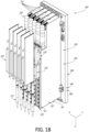
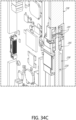
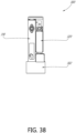
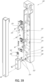
- FIGS 1B-4 show views of a liquid dispenser 100 according to one embodiment of the present disclosure.
- Liquid dispenser 100 comprises a manifold 102 that has a front 104, a back 106, and sides 108.
- the manifold 102 is configured to accept one or more pipette channels 110, where each pipette channel 110 houses various components used in aspirate and dispense operations.
- the pipette channel 110 has a front 112, a back 114, and sides 116.
- the liquid dispenser 100 is modular, thereby enabling flexibility and versatility in arranging the one or more pipette channels 110 relative to the manifold 102.
- the front 112 of the pipette channels 110 includes a pipette module 120.
- the pipette module 120 includes pipetting mechanisms that use air under vacuum and pressurized air to aspirate and dispense fluid from a pipette tip 122.
- One non-limiting example pipette tip 120 is the Air Driven OEM Channel Pipettor by Seyonic ® (part number PCNC-0061-00). Pipette tips 122 can be disposable.
- Each pipette module 120 can include a tip adapter 118, wherein each tip adapter 118 is configured to accept a pipette tip 122.
- a pipette tip 122 can be attached to the tip adapter 118, for instance, by Z-direction movement of the pipette module 120 relative to a pipette tip 122.
- a pipette tip 122 can be removed from the tip adapter 118, for instance, by movement of the pipette module 120 relative to a pipette stripper (not shown).
- the liquid dispenser 100 can include independent pipette tip 122 attachment or removal.
- the back 114 of the pipette channel 110 is configured to reversibly connect to, or mate with, the front 104 of the manifold 102, as described herein.
- the manifold 102 in this embodiment is configured to accept as many as five pipette channels 110.
- the manifold 102 can accept fewer than five pipette channels, such as one, two, three, or four pipette channels, and is thus advantageously customizable by an operator based on the particular liquid dispensing requirements of the operator.
- the liquid dispenser 100 shown in Figure 1 has capacity to accept a maximum of five pipette channels 110, other configurations are contemplated.
- the liquid dispenser 100 can be configured to accept a maximum of one pipette channel, two pipette channels, three pipette channels, four pipette channels, five pipette channels, six pipette channels, seven pipette channels, eight pipette channels, nine pipette channels, ten pipette channels, eleven pipette channels, twelve pipette channels, thirteen pipette channels, fourteen pipette channels, fifteen pipette channels, sixteen pipette channels, seventeen pipette channels, eighteen pipette channels, nineteen pipette channels, twenty pipette channels, etc.
- One or more pipette channels 110 can be removed from the manifold 104. In some embodiments, one pipette channel 110 can be removed without removing another pipette channel 110. For instance, one pipette channel 110 may be removed and replaced without removing another pipette channel 110 from the manifold 102.
- each pipette channel 110 has a peg near the top of the pipette channel 110 and a peg near the bottom of the pipette channel 110.
- the pegs can guide alignment between the back 114 of the pipette channel 110 and the front 104 of the manifold 102.
- the pegs can be dowel pins.
- the manifold 102 can include a corresponding slot (not shown) to accept each of the pegs.
- the slots can include a chamfered edge to facilitate insertion of the pegs.
- the manifold 102 can include at least one marking (not shown) to facilitate the alignment of an edge of the pipette channel 110 with the manifold 102.
- the manifold 102 has at least one edge (e.g., top edge, bottom edge, etc.) that aligns with a corresponding edge of the pipette channel (e.g., top edge, bottom edge, etc.).
- the pipette channel 110 can include one or more fasteners 124.
- the fasteners 124 are captive screws.
- each pipette channel 110 has a fastener 124 near the top of the pipette channel 110 and a fastener 124 near the bottom of the pipette channel 110.
- the fasteners 124 can be located near the pegs.
- the fasteners 124 are threaded such that the operator can securely fasten the pipette channel 110 to the manifold 102.
- the fasteners 124 and pegs securing a pipette channel 110 to the manifold 102 are readily adjustable and/or removable by an operator without affecting the operation or connections of another pipette channel 110 that is mated with the manifold 102.
- a first pipette channel 110 that is malfunctioning, requires an adjustment, or is need of regular maintenance or testing can be removed by an operator without affecting the operation or connections of any other pipette channel 110 that is mated with the manifold 102.
- the operator seamlessly replaces the first (now removed) pipette channel 110 with a second pipette channel by connecting the second pipette channel to the manifold 102 with pegs in the location previously occupied by the first (now removed) pipette channel 110.
- the pipette channel 110 can be fixed in position to the manifold 102.
- the manifold 102 can be coupled to a robotic arm (not shown) which can move the manifold 102 in space.
- the motion of the robotic arm can have six degrees of freedom.
- the robotic arm can include 1 degree of translational freedom, 2 degrees of translational freedom, 3 degrees of translational freedom, 1 degree of rotational freedom, 2 degrees of rotational freedom, 3 degrees of rotational freedom, or any combination of these.
- the manifold 102 is coupled to a gantry (not shown) of an automated sample analysis system.
- the gantry can include a bar or rail which allows movement of the manifold 102 along an X-axis of the automated sample analysis system ("the X-direction").
- the gantry can include a bar or rail which allows movement of the manifold 102 along a Y-axis of the automated sample analysis system ("the Y-direction"). Such relative motion can be accomplished by any suitable mechanical movement device, such as but not limited to, gearing, or a rack and pinion assembly, or a lead screw, or a belt drive, or a linear motor.
- the manifold 102 is moveable along a Z-axis of the automated sample analysis system ("the Z-direction"). In other embodiments, movement of the manifold 102 in the Z-direction is prevented.
- movement in the Z-direction is provided by the pipette channel 110.
- the module 120 can include a flange 126.
- the flange 126 can be fixedly attached to a coupling 128.
- the coupling 128 is movable along a track 130.
- the movement of the coupling 128 causes movement of the module 120 in the Z-direction relative to the track 130.
- the track 130 is fixedly attached to a base 132 of the pipette channel 110.
- the base 132 of the pipette channel is stationary relative to manifold 102.
- the movement of the coupling 128 causes movement of the module 120 in the Z-direction relative to the base 132 of the pipette channel 110.
- the movement of the coupling 128 causes movement of the module 120 in the Z-direction relative to the manifold 102.
- Figure 3 shows a cross-sectional view of the liquid dispenser 100 taken along line 3-3 of Figure 2 .
- the coupling 128 can couple to a nut 134 which includes a bore.
- a plurality of ball bearings are arranged around the bore inside the nut 134, which reduce friction when interacting with the ball screw 136.
- the coupling 128 can be integral with the nut 134 configured to interact with a ball screw 136.
- the bore 134 is threaded and interacts with a lead screw (not shown).
- the ball screw 136 can be rotated with a motor 138.
- the ball screw 136 can be coupled to a bearing 140.
- the bearing 140 allows the ball screw 136 to rotate without translation.
- the coupling 128 translates along the ball screw 136.
- the coupling 128 is guided along the track 130 in the Z-direction. Rotation of the ball screw 136 in a first direction causes the coupling 128 to translate downward along the track 130. Rotation of the ball screw 136 in a second, opposite direction causes the coupling 128 to translate upward along the track 130.
- the module 120 includes a mechanism to provide aspirate and dispense operations.
- a sample is only introduced into the system via the pipette tip 122.
- the movement of the coupling 128 allows the pipette tip 122 to be lowered into a container to aspirate and/or dispense a sample or other liquid. After aspirating or dispensing the sample or other liquid in the container, the movement of the coupling 128 allows the pipette tip 122 to be raised above the a container to move the pipette tip 122 to another location, for example over a second container in an automated sample analysis system.
- the aspirate and dispense operations of the module 120 can be controlled, in part, by application of air pressure or vacuum.
- the manifold 102 can include an inlet pressure port 142.
- the manifold 102 can include an inlet vacuum port 144.
- the inlet pressure port 142 can be located on the front 104, back 106, or sides 108 of the manifold 102.
- the inlet vacuum port 144 can be located on the front 104, back 106, or sides 108 of the manifold 102.
- the inlet pressure port 142 and the inlet vacuum port 144 are located on the front 104 of the manifold 102 in the embodiment of Figures 1B-4 , but other configurations are contemplated.
- the manifold 102 includes a pressure channel 146 and a vacuum channel 148.
- the pressure channel 146 is in fluid communication with the inlet pressure port 142.
- the inlet pressure port 142 provides the only entrance to the pressure channel 146.
- the pressure channel 146 exits to one or more pressure cross-channels 150 described herein.
- the inlet pressure 142 can, in some cases, seal the pressure channel 146.
- the vacuum channel 148 is in fluid communication with the inlet vacuum port 144.
- the inlet vacuum port 144 provides the only entrance to the vacuum channel 148.
- the vacuum channel 148 exits to one or more vacuum cross-channels 152 described herein.
- the inlet vacuum port 144 can, in some cases, seal the vacuum channel 148.
- the pressure channel 146 and/or the vacuum channel 148 are formed by drilling a bore from one side 108 of the manifold 102 toward the other side 108 of the manifold 102.
- the bore is a through bore.
- the bore can be plugged or otherwise sealed at the sides 108 of the manifold 102.
- the cross-channel can be any shape of sub-channel connecting at least in part to either a pressure channel or a vacuum channel.
- the cross-channel can form any angle with the pressure channel or a vacuum channel, including 30, 45 degrees, 60 degrees, 75 degrees, and 90 degrees etc.
- the term cross-channel does not imply that the cross-channel necessarily forms a 90 degree intersection with the pressure channel or a vacuum channel.
- the inlet pressure port 142 can be connected to a source of pressurized gas (not shown) via tubing (not shown).
- the pressurized fluid such as a pressurized gas can travel from the inlet pressure port 142 through the pressure channel 146.
- the pressure channel 146 can supply gas under pressure to each pipette channel 110 connected to the manifold 102.
- the inlet vacuum port 144 can be connected to a vacuum source (not shown) via tubing (not shown).
- Gas in the vacuum channel 148 can be supplied with gas under vacuum via the inlet vacuum port 144 and the vacuum source.
- the vacuum channel 148 can supply gas under vacuum to each pipette channel 110 connected to the manifold 102.
- the pressure channel 146 and the vacuum channel 148 can be parallel bores through the manifold 102, as shown.
- the inlet pressure port 142 and the inlet vacuum port 144 can have standard connectors, for example industry-standard connectors that mate with suitable pneumatic tubing.
- the pressure channel 146 is shown extending through the manifold 102.
- the pressure channel 146 is connected to a pressure cross-channel 150.
- the pressure cross-channel 150 extends from the pressure channel 146 in the manifold 102 to the base 132 of the pipette channel 110.
- the pressure cross-channel 150 extends from the front of the manifold 102 to the back of the pipette channel 110.
- the pressure cross-channel 150 can be perpendicular to the pressure channel 146.
- the vacuum channel 148 is shown extending through the manifold 102.
- the vacuum channel 148 is connected to a vacuum cross-channel 152.
- the vacuum cross-channel 152 extends from the vacuum channel 148 in the manifold 102 to the base 132 of the pipette channel 110.
- the vacuum cross-channel 152 extends from the front of the manifold 102 to the back of the pipette channel 110.
- the vacuum cross-channel 152 can be perpendicular to the vacuum channel 148.
- one pipette channel 110 can be removed from the liquid dispenser 100 (for example, disconnected from the front 104 of the manifold 102).
- the corresponding now-exposed pressure cross-channel 150 and vacuum cross-channel 152 may need to be covered.
- the user may install a blanking plate (not shown) that covers the exposed pressure cross-channel 150 and vacuum cross-channel 152.
- the blanking plate can include a peg near the top of the blanking plate and a peg near the bottom of the blanking plate.
- the blanking plate can include a fastener 124 near the top of the blanking plate and a fastener 124 near the bottom of the blanking plate.
- Other mechanisms configured to cover one or more of the pressure cross-channel 150 and vacuum cross-channel 152 are contemplated includes seals, plugs, adhesives, etc.
- the pressure cross-channel 150 and vacuum cross-channel 152 can be sealed such that one or more pipette channels 110 can be removed without adversely impacting the aspirate and dispense operations of another pipette channel 110 mated with the manifold 102.
- the pipette channel 110 is modular allowing the pipette channel 110 to be reversibly secured to and disconnected from the manifold 102.
- the pressure cross-channel 150 and the vacuum cross-channel 152 are structures in the manifold 102.
- the pressure cross-channel 150 associated with each pipette channel 110 spans a distance between the pressure channel 146 and a pressure port 156 on the back 114 of the pipette channel 110 when the pipette channel 110 is secured to the front 104 of the manifold 102.
- the vacuum cross-channel 152 associated with each pipette channel 110 spans a distance between the vacuum channel 148 and a vacuum port 157 on the back 114 of the pipette channel 110 when the pipette channel 110 is secured to the front 104 of the manifold 102.
- the liquid dispenser 100 includes one or more features to improve the seal between the pipette channel 110 and the manifold 102.
- an o-ring 154 seals a fluidic connection (for transfer of a gas, for example) between the pipette channel 110 and the manifold 102.
- the o-rings 154 can be located near the pressure cross-channel 150 and the vacuum cross-channel 152.
- Embodiments of pressure channels 110 of described herein include an individually-actuatable solenoid valve 158 configured to control the flow of gas from the manifold 102to the module 120 of the pressure channel 110.
- One pressure cross-channel 150 and one vacuum cross-channel 152 of the manifold 102 are each connected to the solenoid valve 158 of a corresponding pipette channel 110 when the pipette channel is mated to the manifold 102.
- the solenoid valve 158 can be located within the base 132 of the pipette channel 110.
- the solenoid valve 158 acts as a selector between vacuum and pressure.
- the solenoid valve 158 directs pressurized fluid, such as a gas under pressure, from the pressure cross-channel 150 through a tube 160.
- the tube 160 extends from the solenoid valve 158 to the module 120.
- pressurized fluid can act on a piston within the module 120 to dispense fluid from the pipette tip 122.
- the module 120 can include a second valve (not shown) configured to control the aspirate or dispense operations.
- the second valve can be a solenoid valve.
- the second valve uses pressure and/or vacuum to control the aspirate or dispense operations.
- the module 120 can include a flow sensor to determine how much was aspirated or dispensed.
- the solenoid valve 158 directs fluid under vacuum, such as a gas under vacuum, from the vacuum cross-channel 152 through the tube 160.
- the gas under vacuum is directed through a second tube 162.
- the tube 162 extends from the solenoid valve 158 to the module 120.
- the tube 160 (or the tube 162, depending on the implementation) supplies gas under vacuum to the module 120.
- gas under vacuum can be supplied to the second valve within the module 120 to aspirate fluid into the pipette tip 122.
- the solenoid valve 158 is integrated within the base 132 of the pipette channel 110.
- a solenoid valve in a single pipette channel 110 of the liquid dispenser 100 malfunctions, requires maintenance, testing, inspection, or any other process requiring access to the solenoid valve 158, the entire pipette channel 110 with the affected solenoid valve 158 can be removed from the liquid dispenser 100 and replaced with another pipette channel 110.
- the pipette channel 110 forms a seal with the manifold 102 such that pressure and/or vacuum can be transferred from the manifold 102 to the pipette channel 110.
- the pressure cross-channel 150 and the vacuum cross-channel 152 create a continuous pathway for gas under pressure and gas under vacuum.
- the pipette channel 110 and the manifold 102 form a pneumatic connection via the pressure cross-channel 150 and the vacuum cross-channel 152.
- the pneumatic connection can be a physical connection which is formed when the pipette channel 110 mates with the manifold 102.
- the manifold 102 can be a pneumatic manifold to supply fluid under vacuum and pressurized fluid to each pipette channel 110.
- the pneumatic solenoid valve 158 is integrated into each pipette channel 110 and acts as a selector between vacuum and pressure.
- Pneumatic tubing is reduced or eliminated by integrated, modular pathways in the manifold 102 and the pipette channels 110 of the present disclosure.
- the integrated pathways can be sealed with o-rings at the interface between the manifold 102 and the pipette channels 110.
- Tubing between the solenoid valve 158 and the pipette channel 110 can be eliminated by placement of the solenoid valve 158 within the base 132 of the pipette channel 110.
- the pipette channel 110 can form an electrical connection with the manifold 102.
- the electrical connection can include a physical connection which is formed when the pipette channel 110 mates with the manifold 102.
- the pipette channel 110 can include an electrical connector 166 on the back side 114 of the pipette channel 110.
- the electrical connector 166 can be coupled to a circuit board 168 within the pipette channel 110.
- Each pipette channel 110 can include a circuit board 168 and corresponding electrical connector 166.
- the manifold 102 can include one or more electrical connectors 170 on the front side 104 of the manifold 102.
- Each electrical connector 170 is configured to electrically connect to a corresponding circuit board 168 of a pipette channel 110 mated with the manifold 102.
- the electrical connector 170 can be considered a backplane connector.
- the manifold 102 can include a circuit board 172.
- the electrical connectors 166, 170 can allow communication of electrical signals and control signals between the manifold 102 and the pipette channel 110. As described herein, the control signals can be data signals designed to control one or more operations of the pipette channel 110.
- the electrical signals can include electrical power to the components of the pipette channel 100, such as AC/DC electricity.
- the electrical connectors 166, 170 can allow communication of electrical signals between the circuit boards 168, 172.
- the circuit boards 168, 172 can be printed circuit boards.
- the mating electrical connectors 166, 170 can eliminate or reduce electrical cables and/or connections that are required to form an electrical connection between the manifold 102 and the pipette channels 110.
- the module 120 can include circuit board 164.
- the circuit board 164 can be associated with the aspirate and dispense operations.
- the circuit boards 164, 168, and/or 172 can be electrically connected.
- circuit boards 164 and 168 are physically connected via a ribbon cable 176.
- the ribbon cable 176 can extend along the coupling 128 at the interface between the pipette channel 110 and the module 120.
- the ribbon cable 176 can transmit control signals and electrical signals.
- movement in the Z-direction of the pipette tip 122 engaged to the module 120 is controlled by features housed in the pipette channel 110, for instance, controlled by the circuit board 168.
- the z-axis control hardware can be located within the pipette channel, for instance on circuit board 168.
- the circuit board 164 acts as an interconnect board and also contains the capacitive sense circuit.
- One or more electrical connectors 174 can be located on the front 104, back 106, or sides 108 of the manifold 102. In the illustrated embodiments, all of the electrical connectors 174 are located on the front 104 of the manifold 102. In some embodiments, the number of electrical connectors 174 does not depend on the number of pipette channels 110. For instance, in the illustrated embodiment, three electrical connectors 174 are included regardless of the maximum number of pipette channels 110 the manifold 102 can accept.
- the pipette channel 110 can be designed to accommodate internal wiring and tubing.
- the pipette channel 110 can house the tubes 160, 162 extending from the solenoid valve 158 to the module 120.
- the pipette channel 110 can include a ribbon cable 176 which transmits electrical signals and control signals.
- the electric signals can include signals from the electrical connectors 174.
- the ribbon cable 176 can extend from the electrical connector 166 on the back side 114 of the pipette channel to the module 120.
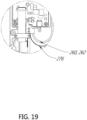
- the tube 160, the tube 162 (if included), and the ribbon cable 176 can each include a bend 178.
- the bends 178 in the tube 160, 162 and the ribbon cable 176 are shown in an upward position in Figure 4 .
- the five pipette channels 110 are located to the left of the electrical connectors 174, the inlet pressure port 142, and the inlet vacuum port 144.
- Implementations of manifold 102 described herein can be configured to accept additional pipette channels 110, which may increase the width of the manifold in the X-direction. Decreasing the number of pipette channels 110 the manifold 102 is configured to accept may decrease the width of the manifold 102 in the X-direction.
- the pipette channels 110 can be arranged such that the pipette tips 122 are aligned. The distance between adjacent pipette tips 122 can be designed to accommodate the spacing of the associated containers for the aspirate and dispense operation.
- the pipette tips 122 are 18 mm apart center to center.
- the associated containers are 9 mm apart center to center. Accordingly, in this non-limiting arrangement, the pipette tips 122 can engage every other container (e.g., a first subset of the containers) in a first position.
- the liquid dispenser 100 can be moved 9 mm to the right or left in the X-direction to engage every other container (e.g., a second subset of the containers).
- features of manifold 102 can be incorporated within a plurality of pipette channels 110 that are permanently secured in a stacked formation adjacent to each other, thereby eliminating the manifold 102.
- the electrical connector 166 of each pipette channel 110 can be located on a side 116 of the pipette channel 110 to communicate signals to and from adjacent pipette channels 110.
- the pressure channel 146 can extend through the stacked pipette channels 110.
- the vacuum channel 148 can extend through the stacked pipette channels 110.
- One or more o-rings 154 can seal the pressure channel 146 and/or vacuum channel 148 between the stacked pipette channels 110.
- the pressure channel 146 and vacuum channel 148 can connect to pressure cross-channels 150 and vacuum cross-channels 152 as described herein.
- Embodiments described herein advantageously enable independent movement of each of a plurality of modules 120 along the Z-axis direction, allowing each of a plurality of samples to be independently and simultaneously aspirated and dispensed within the liquid dispenser 100.
- each of the plurality of pipette channels includes an individually-actuatable coupling 128 that moves along a ball screw 136 to translate the module 120 (independently of other modules 120) relative to the base 132 of the pipette channel 110.
- Embodiments described herein also advantageously reduce pneumatic tubing to modular, individually-actuatable pipette channels.
- Independently operating multiple pipette channels 110 positioned next to each other would typically require multiple pneumatic tubes running to each pipette channel 110 from a common pneumatic pressure and vacuum source.
- the common pneumatic pressure and vacuum source can be a remotely mounted solenoid valve manifold.
- the remotely mounted solenoid valve manifold makes it difficult to route the tubing to each pipette channel 110.
- the pneumatic tubes running to each pipette channel 110 would be both visible and cumbersome.
- the multiple pneumatic tubes may impede motion, such as motion of the liquid dispenser along a gantry.
- the remotely mounted solenoid valve manifold would require much longer tubing or multiple sections of tubing to span from the remotely mounted solenoid valve manifold to each pipette channel 110.
- liquid dispensers described herein reduce pneumatic tubing down to two pneumatic tubes connecting to the manifold 102; that is, one pneumatic tube (not shown) connecting to the inlet pressure port 142 and one pneumatic tube (not shown) connecting to the inlet vacuum port 144.
- Each pipette channel 110 is supplied pressurized gas and gas under vacuum through the pressure channel 146 and vacuum channel 148, respectively. This eliminates separate pneumatic tubing to each pipette channel 110. In other embodiments, separate pneumatic tubing is supplied to each pipette channel 110.
- a separate piece of pneumatic tubing 160, 162 is provided inside each pipette channel 110 that connects the module 120 to the solenoid valve 158.
- a separate piece of pneumatic tubing 160, 162 is provided inside each pipette channel 110 that connects the module 120 to the solenoid valve 158.
- embodiments described herein also reduce electrical connections to modular, individually-actuatable pipette channels. Independently operating multiple pipette channels 110 positioned next to each other would typically require multiple electrical cables running to each pipette channel 110 from a common controller.
- the embodiments described herein reduce electrical cables down to three electrical connectors 174 connecting to the manifold 102.
- Each pipette channel 110 is electrically connected to the electrical connectors 174.
- signals from the Ethernet connection are sent to each pipette channel 110 that is interchangeably mated to the manifold 102.
- signals from the module connection are sent to each module 120 of the plurality of pipette channels 110 that are interchangeably mated to the manifold 102. This eliminates separate cabling to each pipette channel 110.
- separate electrical connections are provided to each pipette channel 110.
- Embodiments described herein also eliminate pneumatic tubing between the solenoid valve 158 and the pipette channel 110.
- a separate pneumatic solenoid manifold would be mounted in close proximity to the pipette channels 110. Pneumatic tubing would connect the solenoid manifold to each pipette channel 110.
- the solenoid valve 128 is integrated within the pipette channel 110.
- Each pipette channel 110 can include a solenoid valve 158. This eliminates the separate solenoid manifold and the associated pneumatic tubing running from the separate solenoid manifold to each pipette channel 110.
- the solenoid valves 158 are not located within the pipette channels 110.
- the solenoid valves can be located in the manifold 102. Pneumatic cross-channels similar to those described above can connect the solenoid valves in the manifold 102 to channels in the pipette channels 110 mated to the manifold 102.
- pneumatic tubing is still eliminated because pneumatic cross-channels between the manifold 102 and the modular, individually-actuatable pipette channels 110 are formed when the pipette channels 110 are mated to the manifold 102.
- each pipette channel 110 can independently control the Z-movement of the pipette module 120. In some embodiments, each pipette channel 110 can independently control the aspirate and/or dispense operations of the pipette module 120. In some embodiments, each pipette module 120 is controlled independently. In some embodiments, two or more pipette modules 120 can move simultaneously, in the same or different operations. In some embodiments, each pipette channel 110 includes one or more solenoid valves 158 which selects between vacuum and pressure. In some embodiments, the second valve within the module 120independently controls aspirate and dispense operations.
- the modular pipette channels 110, 210, 310, 410 described herein can be compact.
- a single pipette channel 110, 210, 310, 410 in accordance with the present disclosure is 0.689 inches (or 17.5 mm) wide in the X-direction, 7.020 inches (or 178.3 mm) deep in the Y-direction, and 13.228 inches (or 336 mm) tall in the Z-direction.
- Implementations of the manifold 102, 202, 302, 402 described herein can be compact.
- the manifold 202 in accordance with the present disclosure is 3.8583 inches (or 98 mm) wide in the X-direction, 2.0472 inches (or 52 mm) deep in the Y-direction, and 15.1969 inches (or 386 mm) tall in the Z-direction.
- the manifold 402 in accordance with the present disclosure is 3.295 inches (or 83.7 mm) wide in the X-direction, 0.8268 inches (or 21 mm) deep in the Y-direction, and 13.2283 inches (or 336 mm) tall in the Z-direction.
- the module 120, 220, 320, 420 can be compact.
- a module 120, 220, 320, 420 in accordance with the present disclosure is 0.6693 inches (or 17 mm) wide in the X-direction, 3.0551 inches (or 77.6 mm) deep in the Y-direction, and 10.2441 inches (or 260.2 mm) tall in the Z-direction including the tip adaptor 118, 218, 318, 418.
- the lengths of tubing and/or wiring can be reduced. In some embodiments, faster switching between vacuum and pressure can be accomplished due to the close proximity of the solenoid valve 158 to the module 120.
- Still another advantage of embodiments described herein includes the modularity of the pipette channels 110.
- One or more pipette channels 110 can be removed and/or replaced without removing one or more adjacent pipette channels 110.
- liquid dispenser 100 illustrated in Figures 1B-4 are also applicable to other liquid dispensers of the present disclosure, for example liquid dispenser 1, liquid dispenser 200, liquid dispenser 300, liquid dispenser 400, and liquid dispenser 500 described in detail below.
- FIGS. 5-34 show views of a liquid dispenser 200 according to another embodiment of the present disclosure.
- the liquid dispenser 200 can include features that are substantially similar to features described above with reference to the liquid dispenser 100.
- the liquid dispenser 200 can include the features of a manifold 202, with a front 204, a back 206, and sides 208.
- the liquid dispenser 200 can include the features of one or more pipette channels 210, with a front 212, back 214, and sides 216.
- the liquid dispenser 200 can include the features of a module 220 with a flange 226, a coupling 228, a pipette tip 222, and a tip adapter 218.
- the liquid dispenser 200 can include the features of a track 230 and a base 232.
- the liquid dispenser 200 can include the features of a nut 234 configured to interact with a ball screw 236, a motor 238, and a bearing 240.
- the liquid dispenser 200 can include the features of an inlet pressure port 242, an inlet vacuum port 244, a pressure channel 246, a vacuum channel 248, a pressure cross-channel 250, a vacuum cross-channel 252, a pressure port 256, a vacuum port 257, and one or more o-rings 254.
- the liquid dispenser 200 can include the features of a solenoid valve 258, and one or more tubes 260, 262.
- the liquid dispenser 200 can include the features of a connector 266 and circuit board 268 of the of the pipette channel 210.
- the liquid dispenser 200 can include the features of a connector 270 and circuit board 272 of the manifold 202.
- the liquid dispenser 200 can include the features of a circuit board 264 of the module 220.
- the liquid dispenser 200 can include the features of electrical connectors 274.
- the liquid dispenser 200 can include the features of a ribbon cable 276, a bend 278, and a groove 280.
- the liquid dispenser 200 can include any of the features of the liquid dispensers described herein.
- the inlet pressure port 242 and the inlet vacuum port 244 of the liquid dispenser 200 are located on the back 206 of the manifold 202.
- the electrical connectors 274 are also located on the back 206 of the manifold 202.
- Embodiments of liquid dispensers described herein that employ this configuration advantageously reduce the width of the liquid dispenser 200 along the X-direction.
- the circuit board 264 of the module 220 can be shorter in the Z-direction than the embodiment in Figures 1B-4 .
- the circuit board 264 and the module 220 can be enclosed in a housing.
- the liquid dispenser 200 can include a mechanism configured to eject a single pipette tip of a plurality of pipette tips 222, as shown in Figures 30-31 .
- the liquid dispenser can include a tip eject motor 282.
- the tip eject motor 282 can be connected to a translating sleeve 284 that encases a portion of the tip adapter 218.
- the tip eject motor 282 can rotate which exerts a downward force on the sleeve 284, causing it to move in the Z-direction relative to the tip adapter 218.
- the downward force on the sleeve 284 overcomes a friction fit between the pipette tip 222 and the tip adapter 218 such that the pipette tip 222 is ejected or disengaged from the tip adapter 218.
- the liquid dispenser 200 can include features which sense whether a pipette tip 222 is engaged with the module 220.
- the liquid dispenser 200 can include a sensor 286.
- the sensor 290 is a REED sensor which senses a magnetic field.
- a component associated with the pipette tip 222 such as the sleeve 284 can include a magnet 286.
- a pipette tip 222 is engaged when the motor 238 drives the entire module 220 down to engage the pipette tip 222.
- the motor 238 in this implementation is the main z-axis motor.
- the sleeve 284 When the module 220 engages the pipette tip 222, the sleeve 284 translates upward from contact with the pipette tip 222 to allow the pipette tip 222 to engage the tip adapter 218. To engage a pipette tip 222, the module 220 translates downward in the Z-direction and pushes down on the pipette tip 222 until the pipette tip 222 snaps on, forms a friction fit, or otherwise engages the tip adapter 218. When a pipette tip 222 is loaded on the module 220 and the sleeve 284 is in this first, "engaged" position, the magnet 286 is in close proximity to the sensor 290.
- liquid dispensers described herein can also include magnetic braking features.
- FIGS 34C and 34D show other features of the liquid dispenser.
- the ball screw 236 can be rotated with a motor 238.
- the coupling 228 can include a nut which includes a bore 229.
- a plurality of ball bearings (not shown) are arranged around the bore 229 inside the nut, which reduce friction when interacting with the ball screw.
- the ball bearing s can rotate within a helical groove of the ball screw 236. As one example, as the ball screw 236 rotates, a ball bearing travels around the ball screw 236 within the groove of the ball screw 236 and a groove in the nut.
- Figures 56-57 show views of a liquid dispenser 400 according to another embodiment of the present disclosure.
- the liquid dispenser 400 can include features that are substantially similar to features described above with reference to the liquid dispenser 100, the liquid dispenser 200, and the liquid dispenser 300.
- the liquid dispenser 400 can include the features of a manifold 402, with a front 404, a back 406, and sides 408.
- the liquid dispenser 400 can include the features of one or more pipette channels 410, with a front 412, back 414, and sides 416.
- the liquid dispenser 400 can include the features of a module 420 with a flange 426, a coupling 428, a pipette tip 422, and a tip adapter 418.
- the liquid dispenser 400 can include pipette channels 410 similar to pipette channels 210.
- the liquid dispenser 400 can include manifold 402 similar to manifold 302.
- the manifold 402 is configured to accept one or more pipette channels 410.
- the inlet pressure port 442 can supply gas under pressure to one or more pressure cross-channels.
- the inlet vacuum port 444 can supply gas under vacuum to one or more vacuum cross-channels.
- Figures 58-60 show views of the liquid dispenser 200 described above operably coupled to a robot 500.
- the robot 500 in this implementation is a separate robotic assembly that is used to perform various functions within a diagnostic testing system, for example pick up PCR plates in this example diagnostic testing system.
- the robot 500 travels with the liquid dispenser 200.
- the robot 500 does not control the motion of the liquid dispenser.
- the liquid dispenser 200 and the robot 500 are coupled to a robotic gantry (not shown) that has three degrees of freedom. The degrees of freedom can include movement in the X direction, Y direction, and rotation.
- the column 600 can connect to the robotic gantry (not shown). Any of the liquid dispensers described herein can be operably coupled to a robot 500.
- the manifolds 102, 202, 302, 402 can be coupled to a robotic arm of robot 500 which can move the manifold in space.
- the motion of the robotic arm can have six degrees of freedom.
- the robotic arm can include 1 degree of translational freedom, 2 degrees of translational freedom, 3 degrees of translational freedom, 1 degree of rotational freedom, 2 degrees of rotational freedom, 3 degrees of rotational freedom, or any combination of these.
- FIGS 61-64 show views of interior portions of some features of the liquid dispenser 300 described above.
- the pipette channel 310 can be designed to accommodate internal wiring and tubing.
- the pipette channel 310 can include the tubes 360, 362 extending from the solenoid valve 358 to the module 320.
- the pipette channel 310 can include a ribbon cable 376 which transmits electrical signals and control signals.
- the ribbon cable 376 can extend from the connector 366 to the module 320.
- the tubes 360, 362, and the ribbon cable 376 can each include a bend 378.
- the bends 378 are shown in a downward position in Figure 61 .
- the downward position of the bends 378 in the tubes 360, 362 and the ribbon cable 376 corresponds to a downward position of the module 320.
- the bends 378 are shown in an upward position in Figure 62 .
- the upward position of the bends 378 corresponds to an upward position of the module 320.
- the bends 378 in the tubes 360, 362 and the ribbon cable 376 move downward within the base 332 of the pipette channel 310.
- the bends 378 can be accommodated within a groove 380 in the base 332 of the pipette channel 310.
- movement in the Z-direction of the pipette tip engaged to the module 320 relative to the manifold 302 is controlled by features housed in the pipette channel 310.
- the module 320 can include the flange 326.
- the flange 326 can be fixedly attached to the coupling 328.
- the coupling 328 is movable along the track 330.
- the movement of the coupling 328 in the Z-direction causes movement of the module 320 in the Z-direction relative to the track 330.
- the movement of the coupling 328 in the Z-direction causes movement of the module 320 in the Z-direction relative to the base 332 of the pipette channel 310.
- the coupling 328 can include the nut 334.
- the nut 334 is configured to interact with the ball screw 336.
- the nut 334 can include ball bearings which reduce friction when interacting with the ball screw 336.
- the nut 334 is threaded and interacts with a lead screw (not shown), rather than the ball screw 336 of this embodiment.
- the ball screw 336 can be rotated with the motor 338. As the ball screw 336 is rotated, the coupling 328 translates along the ball screw 336. The coupling 328 is guided along the track 330 in the Z-direction. Rotation of the ball screw 336 in a first direction causes the coupling 328 to translate downward in the Z-direction along the track 330. Rotation of the ball screw 336 in a second, opposite direction causes the coupling 328 to translate upward in the Z-direction along the track 330.
- the liquid dispensers described herein can be configured to carry out pipetting operations in parallel, with each pipette channel acting independently to aspirate and dispense liquid.
- Each pipette channel has the ability to move its corresponding pipette tip along the z-axis of the liquid dispenser independently of movement of another pipette tip mounted in the liquid dispenser.
- a liquid dispenser as described herein, is an assembly of pipette channels that together cooperate to carry out such pipetting operations on solutions.
- the liquid dispenser thus, typically, can pick up and disengage pipette tips as needed, as well as aspirate quantities of liquid up into, and dispense those quantities of liquid from, such pipette tips.
- the motions and operation of the liquid dispenser is typically controlled by a processor such that pipetting operations can be automated.
- the liquid dispenser can be configured to align pipette tips, e.g., with containers or cartridge inlet holes.
- the liquid dispenser can be configured so that the module circuit board, sensors (for example, but not limited to, sensors to detect presence of pipette tips and sensors to detect force exerted on pipette tips during pipetting), the tip eject motor, the sleeve, the pipette tip and other items, move as a unit as the module, thereby minimizing the number of control lines that move across the instrument during use, reducing the likelihood that such control lines will become tangled during motion of the module, and increasing the likelihood that the module will remain in communication with other components that are fixed at various points within a preparatory or diagnostic apparatus such as the base of the pipette channel and the manifold.
- sensors for example, but not limited to, sensors to detect presence of pipette tips and sensors to detect force exerted on pipette tips during pipetting
- the tip eject motor for example, but not limited to, sensors to detect presence of pipette tips and sensors to detect force exerted on pipette tips during pipetting
- the layout of the components in the figures is for convenience only, and one of skill in the art would appreciate that other arrangements are possible, depending upon environment and other factors.
- the electrical components including the motors, pumps, and valves, can receive instructions from a processor (not shown).
- the processor can be located on the liquid dispenser or can be remote from the liquid dispenser.
- Embodiments of liquid dispensers described herein can also include a sensor configured to sense when vertical motion of the module is obstructed, and to provide a suitable signal directly to a processor (not shown), or indirectly (not shown) via printed circuit board.
- the sensor can be mounted on the module or on another component of the pipette channel.
- the scanner can be configured to read information (for example, but not limited to, sample and patient information), from one or more of a container holding a liquid, a sample tube, a reagent holder, a microfluidic cartridge, or any other container.
- the scanner can be electrically connected directly (not shown) to a processor, or indirectly via a printed circuit board.
- Embodiments of liquid dispensers described herein include pneumatic solenoid valves, but other valves are contemplated.
- the valve can be associated with each pipette channel, and serve to control operation of each module such as by, for example, controlling when to reduce pressure, thereby causing a aspirating operation, or to increase pressure, thereby causing a dispense operation.
- Each valve is connected to (including being in fluid communication with) the module via one or more internal tubes which extend from the valve to the module.
- the manifold of liquid dispensers described herein can be connected to a pump (not shown) via an air-line or tubing (not shown) to the inlet pressure port and inlet vacuum port.
- the inlet pressure port and inlet vacuum port are connected via one or more channels and cross-channels in the manifold to ports in the pipette channel.
- the ports in the pipette channel supply gas under pressure and gas under vacuum to a valve located within the pipette channel.
- Each pipette channel contains an independently controllable solenoid valve that selectively diverts air from the pump to the module associated with the pipette channel, and therefore to a corresponding pipette tip.
- Operation of liquid dispenser is typically controlled by one or more circuit boards (PCB), including circuit board 164 within the module 120.
- the PCB additionally can receive electrical signals from electrical connectors, including electrical connectors 170.
- the aspirate and dispense operations can be precisely controlled, by signals from the PCB, so that accurate volumetric control is achieved.
- calibration of the liquid dispenser is required so that the amount of time to force or to aspirate gas that is required to dispense or aspirate a desired volume of liquid is known.
- the time between a valve opening and valve closing, as controlled by signals is known and can be incorporated into the control software.
- the liquid dispense operations can be controlled by the hardware and software located within the liquid dispenser.
- the liquid dispense operations can be controlled by the hardware and software located within the module 120.
- the module 120 can include the second valve, as described herein.
- the module 120 can include a pump (not shown) and a motor (not shown) controlling its action.
- the pump includes a translating plunger controlled by a stepper motor, which receives electrical signals and/or control signals as input.
- the module 120 can include any hardware and/or software configured to complete aspirate and dispense operations.
- a lane and the one or more components of the liquid dispenser accepted thereon can be considered a unit.
- a unit can be defined by function.
- the unit can be defined by the ability to perform aspirate and dispense operations.
- Two units of a liquid dispenser can perform the same aspirate and dispense operations simultaneously.
- Two units of a liquid dispenser can perform different aspirate and dispense operations simultaneously.
- Two units of a liquid dispenser can perform the same aspirate and dispense operations simultaneously.
- Two units of a liquid dispenser can independently control aspirate and dispense operations.
- Two units of a liquid dispenser can include two modules which independently perform aspirate and dispense operations.
- Two units of a liquid dispenser can independently control movement in the Z-direction.
- Two units of a liquid dispenser can include two valves which can independently select between vacuum and pressure.
- a unit includes a lane of the manifold and a selectively receivable component received in the lane.
- the selectively receivable component can include a pipette channel, a pipette module, a pipette channel coupled to a pipette module, or a blanking plate.
- each pipette channel coupled to the manifold moves as a unit with the manifold.
- the manifold can move in the X-direction, along the width of the manifold.
- the movement of the manifold in the X-direction causes movement in the X-direction of each pipette channel coupled to the manifold.
- the manifold can move in the Y-direction, along the thickness of the manifold.
- an advantage is the ability to mount the manifold to any of a variety of gantry systems with no or very little modification of the manifold.
- the manifold is coupled to a gantry that is controlled by one or more belt drives.
- the gantry is controlled by one or more stepper motors.
- the gantry is controlled by one or more linear motors.
- a liquid dispenser system includes three manifolds, each mounted on a separate rail configured to travel along the Y-axis of the system.
- the linear motors advantageously allow the multiple manifolds mounted on separate Y-direction rails to move along the same X-direction rail.
- an advantage is that the linear motors allow three manifolds mounted on three separate Y-direction rails to move along the same X-direction rail.
- the pipette channel is calibrated for a specific function. In some embodiments, the pipette channel is configured in shape or design for a specific function. In some embodiments, the pipette channel is configured for a specific lane assignment. The pipette channel can dictate the lane where the pipette channel is placed. In some embodiments, two pipette channels coupled to a manifold have the same calibration settings. In some embodiments, two pipette channels coupled to a manifold have different calibration settings. In some embodiments, two pipette channels of two or more liquid dispensers have the same calibration settings. In some embodiments, two pipette channels of two or more liquid dispensers have different calibration settings.
- an advantage is the ability to select between two pipette channels with different calibration settings related to volume.
- a manifold can include one pipette channel with a selected calibration setting, multiple pipette channels configured with the same selected calibration setting, or multiple pipette channels configured with different selected calibration settings.
- a pipette channel can include be calibrated to dispense smaller volumes than another pipette channel mounted to the same manifold.
- a pipette channel can be calibrated to dispense greater volumes than another pipette channel mounted to the same manifold.
- a pipette tip is mounted to a pipette channel configured to dispense 1 mL of liquid.
- a pipette tip is mounted to a pipette channel configured to dispense 5 mL of liquid. In some embodiments, a pipette tip is mounted to a pipette channel configured to dispense between 0.5 mL and 1 mL of liquid. In some embodiments, a pipette tip is mounted to a pipette channel configured to dispense between 1 mL and 5 mL of liquid.
- a plurality of pipette channels, each independently configured to dispense a particular volume, or range of volumes, can be selected and mounted to a manifold based on the particular liquid dispensing requirements of the system in which the manifold is installed.
- an advantage is the ability to select between two pipette channels with different calibration settings related to pressure.
- a manifold can include one pipette channel with a selected calibration setting, multiple pipette channels configured with the same selected calibration setting, or multiple pipette channels configured with different selected calibration settings.
- a pipette tip is mounted to a pipette channel configured to dispense a liquid at 500 millibar.
- a pipette tip is mounted to a pipette channel configured to dispense a liquid at between 250 millibar and 750 millibar.
- a pipette tip is mounted to a pipette channel configured to dispense a liquid at less than 750 millibar.
- a pipette tip is mounted to a pipette channel configured to dispense a liquid at less than 500 millibar. In some embodiments, a pipette tip is mounted to a pipette channel configured to dispense a liquid at less than 250 millibar.
- the pressure is set by a pressure controller. The pressure controller can provide vacuum and pressure to the manifold. The pressure controller can provide instructions to control the vacuum and pressure supplied to the manifold. In some embodiments, all pipette channels coupled to a single manifold are provided with gas at the same pressure.
- the system may include one pressure controller that feeds gas to the manifold, and all pipette channels coupled to the manifold are provided with gas at the same pressure.
- the pressure controller can change the pressure of the gas provided to all pipette channels coupled to the manifold.
- Figures 65A-65B illustrate an embodiment of the manifold 600, the features of which can be used in combination with any manifold described herein.
- the manifold 600 is designed to provide gas to a first set of pipette channels coupled to a single manifold at a first pressure and to simultaneously provide gas to a second, different set of pipette channels coupled to the same single manifold at a second, different pressure.
- a manifold configured to supply gas under varying pressure.
- the system can include two or more separate pressure controllers simultaneously providing gas at different pressures to the same single manifold. Other configurations are possible.
- pressure inlet 602 pressure inlet 604
- vacuum inlet 606 vacuum inlet 608 of the manifold 600.
- Each pressure source is connected to a single pressure channel and each vacuum source is connected to a single vacuum channel, such that the manifold has two pressure channels 612, 614 and two vacuum channels 616, 618.
- the manifold is split so the first pressure source and the first vacuum source supply gas to a first set of lanes of the manifold.
- the second pressure source and the second vacuum source supply gas to a second, different set of lanes of the manifold.
- the manifold can be divided in various combinations.
- the pipette channels that receive gas from the same pressure channel and the same vacuum pressure channel are adjacent.
- the mating cross-channels, pressure cross-channel 620 and vacuum cross-channel 622, for the vacuum and pressure channels can be the same locations as other embodiments described herein.
- the cross-channels 620, 622 can be in the same position regardless of the number or location of the pressure channels and vacuum channels located within the manifold.
- the manifold includes a first pressure channel that is physically and fluidically isolated from a second pressure channel, both of which are physically and fluidically isolated from a vacuum channel in the manifold.
- the valve of the pipette channel is coupled to the first pressure channel, the second pressure channel, and the vacuum channel and is designed to switch between the channels to divert gas at a first pressure from the first pressure channel, divert gas at a second, higher pressure from the second pressure channel, or divert gas under vacuum to the dispense head.
- the valve of the pipette channel can be designed to switch between two or more vacuum channels in the manifold.
- the valve of the pipette channel can be designed to switch between three or more channels supplying gas under pressure and/or gas under vacuum.
- the pipette channel includes two solenoid valves in each pipette channel to distribute gas under pressure or gas under vacuum.
- the options for three gas sources include, but are not limited to, two pressure sources and one vacuum source; one pressure source and two vacuum sources, etc.
- the pipette channel may include three solenoid valves in each pipette channel to distribute gas under pressure or gas under vacuum.
- the manifold can be coupled to other types of pressure sources that separately supply gas under pressure and gas under vacuum to the valves in two or more pipette channels.
- a plurality of pipette channels each independently configured to dispense a liquid at a different pressure, or range of pressures, can be selected and mounted to a manifold based on the particular liquid dispensing requirements of the system in which the manifold is installed.
- an advantage is the ability to select between two pipette channels with different calibration settings related to speed.
- a manifold can include one pipette channel with a selected calibration setting, multiple pipette channels configured with the same selected calibration setting, or multiple pipette channels configured with different selected calibration settings.
- a pipette channel can include a calibration for faster aspirate and dispense operations than another pipette channel, such as for high speed operations.
- a pipette channel can include a calibration for slower aspirate and dispense operations than another pipette channel.
- an advantage is the ability to select between two pipette channels with different calibration settings related to force.
- a manifold can include one pipette channel with a selected calibration setting, multiple pipette channels configured with the same selected calibration setting, or multiple pipette channels configured with different selected calibration settings.
- a pipette channel can be calibrated to engage or disengage a pipette tip with greater force than another pipette channel mounted to the same manifold.
- a first pipette channel that interacts with one or more samples is configured to engage a pipette tip with greater force to prevent inadvertent disengagement of the pipette tip from the tip adapter by swabs within a sample tube.
- a second pipette channel that interacts with reagents in reagent tubes is configured to engage a pipette tip with lesser force than the first pipette channel, because the second pipette channel will not interact with objects in a reagent tube that may inadvertently disengage the pipette tip, such as a sample swab.
- an advantage is the ability to select between two pipette channels with different configurations.
- the two pipette tips can have different configurations related to differently sized pipette tip adapters.
- a manifold can include one pipette channel with a selected calibration setting, multiple pipette channels configured with the same selected calibration setting, or multiple pipette channels configured with different selected calibration settings.
- two pipette channels can include different tip adapters.
- a pipette channel can include a larger tip adapter for a larger pipette tip than another pipette channel.
- a pipette channel can include more features than another, lower cost pipette channel.
- the two pipette channels can have a different configuration of the pipette module, for example, as shown in Figure 35 where the pipette module 320 is mounted adjacent to a side 316 of the pipette channel 310 along the X-axis of the liquid dispenser 300.
- an advantage is the ability to design a liquid dispenser configured to accept two or more pipette channels that have different features, such as but not limited to different calibration settings or configurations.
- the two or more different pipette channels can have the same configuration of electrical connectors designed to mate with the electrical connectors of the manifold.
- the two or more different pipette channels can have the same configuration of pneumatic connections.
- the two or more different pipette channels can have one or more different dimensions (e.g., height, thickness, width).
- the two or more different pipette channels can have different modules.
- the two or more different pipette channels can accept differently sized pipette tips.
- the two or more different pipette channels can have different tip adapters.
- the two or more different pipette channels can be calibrated to dispense fluids in different ways, such as but not limited to calibrated to dispense different volumes of fluid or calibrated to dispense fluid at different pressures.
- two or more different pipette channels are configured to be accepted on any lane of the manifold.
- an advantage is the ability to design a manifold including two or more different lanes wherein each lane is configured to accept pipette channels that are the same.
- the two or more different lanes can have the same configuration of electrical connectors within the lane.
- the two or more different lanes can have the same configuration of pneumatic connection.
- the two or more different lanes can have one or more different dimensions (e.g., height, thickness, width).
- an advantage is the ability to design a manifold including two or more different lanes wherein each lane is configured to accept a pipette channel that is different from pipette channels mounted in other lanes.
- an advantage is the ability to design a system including two or more different liquid dispensers with different manifolds, the different manifolds having certain features in common and certain features which are different.
- one lane of each of the two or more different manifolds can have the same configuration of electrical connectors within the lane.
- one lane of each of the two or more different manifolds can have the same configuration of pneumatic connections.
- one lane of each of the two or more different manifolds in the same system can have one or more different dimensions (e.g., height, thickness, width).
- an advantage is the ability to design a manifold configured to accept a specific number of pipette channels.
- the liquid dispenser includes one pipette channel but is configured to include more than one pipette channel.
- the liquid dispenser is configured to include only one pipette channel.
- the liquid dispenser includes three pipette channels but is configured to include more than three pipette channels.
- the liquid dispenser is configured to include only three pipette channels.
- the liquid dispenser includes five pipette channels but is configured to include more than five pipette channels.
- the liquid dispenser is configured to include only five pipette channels.
- an advantage is the ability to control the flow of a gas with a valve within a pipette channel.
- a pipette channel includes an individually-actuatable solenoid valve.
- the solenoid valve is a low pressure solenoid valve.
- the solenoid valve is rated for less than 30 psi.
- the solenoid valve is rated for less than 20 psi.
- the solenoid valve is rated for less than 10 psi.
- the solenoid valve is rated for between 5 and 10 psi.
- the solenoid valve is rated for between 1 and 15 psi.
- the air-lines described herein can accept any suitable gas, such as but not limited to atmospheric air or nitrogen.
- an independent line that connects the module to the solenoid valve is enclosed within the housing of the pipette channel.
- the independent line supplies both pressure and vacuum from the manifold to the module.
- each module includes an independent coupling to the manifold.
- each pipette channel includes a single module.
- each module is coupled to a single lane of the manifold.
- each lane can include an independent electrical connection for the module.
- each lane can include an independent pneumatic connection for the module.
- an advantage is the ability to have a system that can be tailored for a particular process.
- Systems described herein can be tailored for the demands of a laboratory.
- the system can be tailored based on the number of liquid dispensers employed.
- a system can include one liquid dispenser, two liquid dispensers, three liquid dispensers, four liquid dispensers, five liquid dispensers, six liquid dispensers, seven liquid dispensers, eight liquid dispensers, nine liquid dispensers, ten liquid dispensers, etc.
- each liquid dispenser includes a single manifold.
- each manifold includes one or more pipette channels.
- each pipette channel includes a single pipette module.
- Two liquid dispensers of the system can have the same number of pipette channels (e.g., a system including two liquid dispensers each having one pipette channel, a system including two liquid dispensers each having two pipette channels, a system including two liquid dispensers each having three pipette channels, a system including two liquid dispensers each having four pipette channels, or a system including two liquid dispensers each having five pipette channels, etc.).
- pipette channels e.g., a system including two liquid dispensers each having one pipette channel, a system including two liquid dispensers each having two pipette channels, a system including two liquid dispensers each having three pipette channels, a system including two liquid dispensers each having four pipette channels, or a system including two liquid dispensers each having five pipette channels, etc.
- Two liquid dispensers of the system can have a different number of pipette channels (e.g., a system including a liquid dispenser with one pipette channel in combination with a liquid dispenser with two pipette channels, three pipette channels, four pipette channels, or five pipette channels; a system including a liquid dispenser with two pipette channels in combination with a liquid dispenser with three pipette channels, four pipette channels, or five pipette channels; a system including a liquid dispenser with three pipette channels in combination with a liquid dispenser with four pipette channels or five pipette channels, a system including a liquid dispenser with four pipette channels in combination with a liquid dispenser with five pipette channels, etc.)
- pipette channels e.g., a system including a liquid dispenser with one pipette channel in combination with a liquid dispenser with two pipette channels, three pipette channels, four pipette channels, or five pipett
- an advantage is the ability to have two or more liquid dispensers of a system perform the same function.
- two or more liquid dispensers of a system can receive instructions from a processor.
- the two or more liquid dispensers of a system can receive the same instructions to perform the same method.
- the two or more liquid dispensers can move in the same pattern of movements.
- the two or more liquid dispensers can perform the same method over the same period of time.
- one or more pipette channels of the two or more liquid dispensers can perform the same aspirate and dispense operations.
- an advantage is the ability to have two or more liquid dispensers of a system perform different functions.
- Two or more liquid dispensers of a system can receive instructions from a processor.
- the two or more liquid dispensers of the system can receive different instructions to perform different methods.
- one liquid dispenser of a system can interact with one or more biological samples of one or more patients contained in sample tubes.
- Another liquid dispenser of the system can interact with one or more reagents contained in reagent tubes.
- the two or more liquid dispensers of the system can include different calibration settings, as described herein.
- the liquid dispenser of the system that interacts with one or more biological samples may be calibrated to require a greater force to engage and disengage pipette tips than the liquid dispenser of the system that interacts with one or more reagents.
- An advantage is that the greater force may reduce the disengagement of pipette tips due to swabs within the sample tubes.
- the pipette channel that interacts with one or more biological samples may require at least 5 pounds of force to engage or disengage a pipette tip to a tip adapter.
- the pipette channel that interacts with one or more biological samples may require at least 10 pounds of force to engage or disengage a pipette tip to a tip adapter.
- the pipette channel that interacts with one or more reagents contained in reagent tubes may require less than 5 pounds of force to engage or disengage a pipette tip to a tip adapter. In some embodiments, the pipette channel that interacts with one or more reagents contained in reagent tubes may require less than 10 pounds of force to engage or disengage a pipette tip to a tip adapter.
- Liquid dispensers described herein can be advantageously tailored for a particular process.
- two pipette channels coupled to a manifold are similar or identical.
- two or more pipette channels of a liquid dispenser can perform the function (e.g., both pipette channels interact with one or more samples in sample tubes, both pipette channels interact with one or more reagents in reagent tubes, etc.).
- two or more pipette channels of a liquid dispenser can have the same shape or configuration.
- two or more pipette channels of a liquid dispenser can have the same calibration settings.
- two pipette channels coupled to a manifold have different features.
- two or more pipette channels of a liquid dispenser can perform different functions (e.g., a pipette channel interacts with one or more samples in sample tubes and a pipette channel coupled to the same manifold interacts with one or more reagents in reagent tubes).
- two or more pipette channels of a liquid dispenser can be configured with different calibration settings.
- the pipette channel that interacts with one or more biological samples in sample tubes may be calibrated to engage and disengage pipette tips with a greater force than the pipette channel of the liquid dispenser that interacts with one or more reagents in reagent tubes.
- two or more pipette channels of a liquid dispenser can have a different shape or configuration.
- a liquid dispenser can have mixed-purpose pipette channels.
- Systems described herein substantially reduce the likelihood of incorrectly connecting the electrical connectors between the pipette channel and the manifold, reducing the risk of damage to the electrical connectors.
- the electrical connector of the pipette channel is automatically aligned with the electrical connector of the manifold when the pegs of the pipette channel are aligned.
- an advantage is the ability to substantially reduce the likelihood of incorrectly connecting pipette channels to electrical sources.
- the manifold is connected to one or more outside sources (e.g., Ethernet connector, power connector, pipettor communication connector).
- one or more pipette channels are connected to the outside sources via the manifold.
- the manifold includes an internal system to distribute these connections to each of the pipette channels.
- a traditional liquid dispenser may include separate electrical sources for each dispense head or pipettor. For instance, a traditional liquid dispenser having five pipettors may have five or more separate electrical sources. During installation or repair, these separate electrical sources may be connected to the incorrect pipettor or not connected to any pipettor.
- An advantage is reducing the likelihood of incorrectly connecting electrical sources to one or more pipette channels.
- the pipette channel encloses a solenoid valve that controls whether gas under pressure or gas under vacuum is supplied to the module of a pipette channel.
- the pipette channel encloses a secondary valve, such as a solenoid valve, to control aspirate and dispense operations within the module.
- a solenoid valve such as a solenoid valve
- an advantage is the ability to return an assembled, modular pipette channel to the manufacturer.
- systems described herein include the ability to troubleshoot a malfunctioning or inoperative pipette channel apart from the manifold.
Landscapes
- Chemical & Material Sciences (AREA)
- Health & Medical Sciences (AREA)
- Life Sciences & Earth Sciences (AREA)
- Analytical Chemistry (AREA)
- General Health & Medical Sciences (AREA)
- Chemical Kinetics & Catalysis (AREA)
- Biochemistry (AREA)
- General Physics & Mathematics (AREA)
- Immunology (AREA)
- Pathology (AREA)
- Physics & Mathematics (AREA)
- Clinical Laboratory Science (AREA)
- Hydrology & Water Resources (AREA)
- Medicinal Chemistry (AREA)
- Hematology (AREA)
- Dispersion Chemistry (AREA)
- Automatic Analysis And Handling Materials Therefor (AREA)
- Sampling And Sample Adjustment (AREA)
- Feeding, Discharge, Calcimining, Fusing, And Gas-Generation Devices (AREA)
- Devices For Use In Laboratory Experiments (AREA)
Applications Claiming Priority (5)
| Application Number | Priority Date | Filing Date | Title |
|---|---|---|---|
| US201662340296P | 2016-05-23 | 2016-05-23 | |
| US201662409695P | 2016-10-18 | 2016-10-18 | |
| EP22174705.8A EP4082664B1 (fr) | 2016-05-23 | 2017-02-17 | Distributeur de liquide à support de collecteur pour canaux de pipette modulaires actionnés indépendamment |
| EP17803186.0A EP3463632B1 (fr) | 2016-05-23 | 2017-02-17 | Distributeur de liquide à support de collecteur pour canaux de pipette modulaires actionnés indépendamment |
| PCT/US2017/018282 WO2017204868A1 (fr) | 2016-05-23 | 2017-02-17 | Distributeur de liquide à support de collecteur pour canaux de pipette modulaires actionnés indépendamment |
Related Parent Applications (2)
| Application Number | Title | Priority Date | Filing Date |
|---|---|---|---|
| EP22174705.8A Division EP4082664B1 (fr) | 2016-05-23 | 2017-02-17 | Distributeur de liquide à support de collecteur pour canaux de pipette modulaires actionnés indépendamment |
| EP17803186.0A Division EP3463632B1 (fr) | 2016-05-23 | 2017-02-17 | Distributeur de liquide à support de collecteur pour canaux de pipette modulaires actionnés indépendamment |
Publications (2)
| Publication Number | Publication Date |
|---|---|
| EP4538717A2 true EP4538717A2 (fr) | 2025-04-16 |
| EP4538717A3 EP4538717A3 (fr) | 2025-07-23 |
Family
ID=60248189
Family Applications (3)
| Application Number | Title | Priority Date | Filing Date |
|---|---|---|---|
| EP17803186.0A Active EP3463632B1 (fr) | 2016-05-23 | 2017-02-17 | Distributeur de liquide à support de collecteur pour canaux de pipette modulaires actionnés indépendamment |
| EP25160564.8A Pending EP4538717A3 (fr) | 2016-05-23 | 2017-02-17 | Distributeur de liquide a support de collecteur pour canaux de pipette modulaires actionnes independamment |
| EP22174705.8A Active EP4082664B1 (fr) | 2016-05-23 | 2017-02-17 | Distributeur de liquide à support de collecteur pour canaux de pipette modulaires actionnés indépendamment |
Family Applications Before (1)
| Application Number | Title | Priority Date | Filing Date |
|---|---|---|---|
| EP17803186.0A Active EP3463632B1 (fr) | 2016-05-23 | 2017-02-17 | Distributeur de liquide à support de collecteur pour canaux de pipette modulaires actionnés indépendamment |
Family Applications After (1)
| Application Number | Title | Priority Date | Filing Date |
|---|---|---|---|
| EP22174705.8A Active EP4082664B1 (fr) | 2016-05-23 | 2017-02-17 | Distributeur de liquide à support de collecteur pour canaux de pipette modulaires actionnés indépendamment |
Country Status (8)
| Country | Link |
|---|---|
| US (6) | US10168347B2 (fr) |
| EP (3) | EP3463632B1 (fr) |
| JP (4) | JP6629996B2 (fr) |
| CN (5) | CN115475542B (fr) |
| AU (3) | AU2017269556B2 (fr) |
| CA (2) | CA3070637C (fr) |
| ES (1) | ES2925011T3 (fr) |
| WO (1) | WO2017204868A1 (fr) |
Families Citing this family (44)
| Publication number | Priority date | Publication date | Assignee | Title |
|---|---|---|---|---|
| US8895311B1 (en) | 2001-03-28 | 2014-11-25 | Handylab, Inc. | Methods and systems for control of general purpose microfluidic devices |
| US7829025B2 (en) | 2001-03-28 | 2010-11-09 | Venture Lending & Leasing Iv, Inc. | Systems and methods for thermal actuation of microfluidic devices |
| WO2005011867A2 (fr) | 2003-07-31 | 2005-02-10 | Handylab, Inc. | Traitement d'echantillons contenant des particules |
| US8852862B2 (en) | 2004-05-03 | 2014-10-07 | Handylab, Inc. | Method for processing polynucleotide-containing samples |
| DK3088083T3 (en) | 2006-03-24 | 2018-11-26 | Handylab Inc | Method of carrying out PCR down a multi-track cartridge |
| US11806718B2 (en) | 2006-03-24 | 2023-11-07 | Handylab, Inc. | Fluorescence detector for microfluidic diagnostic system |
| US10900066B2 (en) | 2006-03-24 | 2021-01-26 | Handylab, Inc. | Microfluidic system for amplifying and detecting polynucleotides in parallel |
| US7998708B2 (en) | 2006-03-24 | 2011-08-16 | Handylab, Inc. | Microfluidic system for amplifying and detecting polynucleotides in parallel |
| US8709787B2 (en) | 2006-11-14 | 2014-04-29 | Handylab, Inc. | Microfluidic cartridge and method of using same |
| WO2008060604A2 (fr) | 2006-11-14 | 2008-05-22 | Handylab, Inc. | Système microfluidique utilisé pour amplifier et détecter des polynucléotides en parallèle |
| US9186677B2 (en) | 2007-07-13 | 2015-11-17 | Handylab, Inc. | Integrated apparatus for performing nucleic acid extraction and diagnostic testing on multiple biological samples |
| AU2008276211B2 (en) | 2007-07-13 | 2015-01-22 | Handylab, Inc. | Polynucleotide capture materials, and methods of using same |
| US8182763B2 (en) | 2007-07-13 | 2012-05-22 | Handylab, Inc. | Rack for sample tubes and reagent holders |
| US8105783B2 (en) | 2007-07-13 | 2012-01-31 | Handylab, Inc. | Microfluidic cartridge |
| US8287820B2 (en) | 2007-07-13 | 2012-10-16 | Handylab, Inc. | Automated pipetting apparatus having a combined liquid pump and pipette head system |
| ES2769028T3 (es) | 2011-04-15 | 2020-06-24 | Becton Dickinson Co | Termociclador microfluídico de barrido en tiempo real |
| CN104040238B (zh) | 2011-11-04 | 2017-06-27 | 汉迪拉布公司 | 多核苷酸样品制备装置 |
| AU2013214849B2 (en) | 2012-02-03 | 2016-09-01 | Becton, Dickinson And Company | External files for distribution of molecular diagnostic tests and determination of compatibility between tests |
| CN107076770B (zh) * | 2014-07-28 | 2019-07-12 | 道格拉斯科学有限责任公司 | 用于分析生物样本和试剂的仪器 |
| WO2017204868A1 (fr) | 2016-05-23 | 2017-11-30 | Becton, Dickinson And Company | Distributeur de liquide à support de collecteur pour canaux de pipette modulaires actionnés indépendamment |
| DE202016004140U1 (de) * | 2016-07-05 | 2017-10-08 | Brand Gmbh + Co Kg | Pipettiervorrichtung zum Aspirieren und Dispensieren von Flüssigkeiten |
| EP3739035A4 (fr) * | 2018-02-20 | 2021-04-21 | Yamaha Hatsudoki Kabushiki Kaisha | Dispositif pour le prélèvement d'un sujet biologique |
| US11541342B2 (en) | 2018-03-07 | 2023-01-03 | Lg Electronics Inc. | Indoor unit for air conditioner |
| WO2019209454A1 (fr) * | 2018-04-25 | 2019-10-31 | Siemens Healthcare Diagnostics Inc. | Appareil de commande de pression intelligent et procédés pour maintenir une pression de collecteur dans un appareil d'essai de diagnostic |
| US11280805B2 (en) | 2018-06-05 | 2022-03-22 | Chemthief, Llc | Robot device for collection of solid, liquid and/or multiphase samples |
| US11420197B2 (en) * | 2018-11-05 | 2022-08-23 | Hycor Biomedical, Llc | Apparatus and method for mixing fluid or media by vibrating a pipette using nonconcentric masses |
| KR102102988B1 (ko) | 2019-03-28 | 2020-04-22 | 주식회사 엘지화학 | 면역 검사 장치 및 면역 검사 방법 |
| KR102102987B1 (ko) * | 2019-03-28 | 2020-04-22 | 주식회사 엘지화학 | 면역 검사 방법 및 면역 검사 장치 |
| CN110007103A (zh) * | 2019-04-28 | 2019-07-12 | 北京奥美泰克科技发展有限公司 | 一种紧凑型独立多通道移液工作站 |
| WO2020232605A1 (fr) * | 2019-05-20 | 2020-11-26 | 深圳迈瑞生物医疗电子股份有限公司 | Appareil d'analyse d'échantillons et procédé de commande de sortie de liquide |
| BR112022001723A2 (pt) * | 2019-08-02 | 2022-04-12 | Douglas Scient Llc | Aparelho de aspiração-dispensação e métodos associados |
| CN112892344B (zh) * | 2019-12-03 | 2024-11-05 | 盛美半导体设备(上海)股份有限公司 | 化学液供应装置及半导体设备 |
| EP3862756B1 (fr) * | 2020-02-05 | 2025-04-09 | Sartorius Liquid Handling oy | Montage réglable pour applications de manipulation automatique de liquides |
| CN111830266B (zh) * | 2020-08-06 | 2024-12-17 | 浙江弘瑞医疗科技有限公司 | 一种试剂自动分配装置 |
| CN112657566A (zh) * | 2020-11-19 | 2021-04-16 | 北京化工大学 | 一种自动移液装置 |
| TWI816279B (zh) * | 2021-01-18 | 2023-09-21 | 全球儀器科技股份有限公司 | 液體轉移設備 |
| CN113680409B (zh) * | 2021-08-24 | 2022-12-06 | 中科计算技术西部研究院 | 一种自动配存方法及系统 |
| LU502046B1 (en) * | 2022-05-07 | 2023-11-07 | Dispendix Gmbh | Method for determining a function for determining a volume of liquid to be dispensed |
| WO2024036564A1 (fr) * | 2022-08-18 | 2024-02-22 | 创茂生技股份有限公司 | Dispositif de pipetage rotatif |
| CN115926978A (zh) * | 2022-12-19 | 2023-04-07 | 康达斯(南京)科技有限公司 | 集成化原位观测载物台细胞培养器及其环境控制方法 |
| US20240255538A1 (en) * | 2023-01-30 | 2024-08-01 | Agilent Technologies, Inc. | Liquid dispensing device for filling multiple containers |
| WO2024163963A2 (fr) * | 2023-02-02 | 2024-08-08 | Astrin Biosciences, Inc. | Système de distribution de cellules assisté par air sous pression |
| EP4713143A1 (fr) * | 2023-05-19 | 2026-03-25 | Opentrons Labworks Inc. | Système et procédé d'étalonnage de détection de surface |
| CN120801740A (zh) * | 2024-04-10 | 2025-10-17 | 深圳迈瑞生物医疗电子股份有限公司 | 样本分析仪 |
Family Cites Families (67)
| Publication number | Priority date | Publication date | Assignee | Title |
|---|---|---|---|---|
| US3010467A (en) * | 1958-06-03 | 1961-11-28 | Fischer & Porter Co | Apparatus for introducing gas into a stream of liquid |
| US3444742A (en) * | 1965-12-06 | 1969-05-20 | Univ Of Kentucky Research Foun | Multiple-unit pipetting assembly and pipette for use therein |
| JPS60214262A (ja) * | 1984-04-10 | 1985-10-26 | Kawasaki Steel Corp | 自動定量点滴装置 |
| JPS63286770A (ja) | 1987-05-20 | 1988-11-24 | Toshiba Corp | 医療検査用液体分析装置の分注ノズルと定量分注ポンプ |
| US5252296A (en) | 1990-05-15 | 1993-10-12 | Chiron Corporation | Method and apparatus for biopolymer synthesis |
| US6203759B1 (en) | 1996-05-31 | 2001-03-20 | Packard Instrument Company | Microvolume liquid handling system |
| US5916524A (en) * | 1997-07-23 | 1999-06-29 | Bio-Dot, Inc. | Dispensing apparatus having improved dynamic range |
| DE19754000A1 (de) * | 1997-12-05 | 1999-06-17 | Max Planck Gesellschaft | Vorrichtung und Verfahren zur elektrisch ausgelösten Mikrotropfenabgabe mit einem Dispensierkopf |
| US20030215957A1 (en) * | 1998-02-20 | 2003-11-20 | Tony Lemmo | Multi-channel dispensing system |
| US6787111B2 (en) * | 1998-07-02 | 2004-09-07 | Amersham Biosciences (Sv) Corp. | Apparatus and method for filling and cleaning channels and inlet ports in microchips used for biological analysis |
| US6258324B1 (en) * | 1999-03-15 | 2001-07-10 | Felix H. Yiu | Pipette dispensing block |
| DE29909529U1 (de) * | 1999-06-01 | 1999-08-12 | Festo AG & Co, 73734 Esslingen | Fluidtechnisches Steuergerät |
| JP2001183382A (ja) * | 1999-12-28 | 2001-07-06 | Roche Diagnostics Gmbh | 分注機の動作確認装置および確認方法 |
| US7040144B2 (en) * | 2000-02-23 | 2006-05-09 | Caliper Life Sciences, Inc. | Microfluidic viscometer |
| US6352673B1 (en) * | 2000-03-09 | 2002-03-05 | Rainin Instrument | Ergonomic return springless manual air displacement pipette |
| DE10052819B4 (de) * | 2000-10-24 | 2004-02-19 | Fraunhofer-Gesellschaft zur Förderung der angewandten Forschung e.V. | Pipettensystem und Pipettenarray sowie Verfahren zum Befüllen eines Pipettensystems |
| US6855538B2 (en) * | 2001-06-27 | 2005-02-15 | The Regents Of The University Of California | High-efficiency microarray printing device |
| DE10202996A1 (de) * | 2002-01-26 | 2003-08-14 | Eppendorf Ag | Piezoelektrisch steuerbare Mikrofluidaktorik |
| US7459128B2 (en) * | 2002-08-13 | 2008-12-02 | Molecular Bioproducts, Inc. | Microfluidic mixing and dispensing |
| DE10238564B4 (de) * | 2002-08-22 | 2005-05-04 | Fraunhofer-Gesellschaft zur Förderung der angewandten Forschung e.V. | Pipettiereinrichtung |
| US6908226B2 (en) * | 2003-02-07 | 2005-06-21 | Beckman Coulter, Inc. | Method and apparatus for aspirating liquid from a container |
| US20040203173A1 (en) * | 2003-04-08 | 2004-10-14 | Peck Bill J. | Apparatus and methods for droplet dispensing |
| WO2005011832A2 (fr) * | 2003-07-29 | 2005-02-10 | Sullivan James J | Chromatographe en phase liquide multi-colonnes simultane pour l'echantillonnage direct d'une ligne d'echantillons liquides |
| US7111757B1 (en) * | 2003-09-12 | 2006-09-26 | O'brien Thomas Matthew | Device and method for the volumetric measurement and dispensing of liquids |
| DE10344700A1 (de) | 2003-09-26 | 2005-04-14 | Hirschmann Laborgeräte GmbH & Co. KG | Mehrkanal-Pipettiervorrichtung |
| FR2865145B1 (fr) * | 2004-01-19 | 2006-02-24 | Commissariat Energie Atomique | Dispositif de dispense de gouttelettes microfluidiques notamment pour la cytometrie. |
| US7270789B1 (en) * | 2004-03-15 | 2007-09-18 | Astle Thomas W | Pipettor head having standpipes open at their tops to a pressure/vacuum chamber and method |
| CA2535908C (fr) * | 2005-02-11 | 2009-12-08 | Sakura Finetek U.S.A., Inc. | Ensemble collecteur |
| JP2006250888A (ja) | 2005-03-14 | 2006-09-21 | Ckd Corp | スポットシステム、スポット方法及びスポット装置 |
| EP1872139A2 (fr) * | 2005-04-09 | 2008-01-02 | Cell Biosciences, Inc. | Systeme d'analyse de microvolumes automatise |
| WO2006121764A2 (fr) * | 2005-05-06 | 2006-11-16 | Applera Corporation | Dispositif a capillaires multiples et procede de synthese et de distribution |
| CN100402153C (zh) * | 2005-08-26 | 2008-07-16 | 博奥生物有限公司 | 一种多通道移液装置及其使用方法 |
| DE102005049920A1 (de) | 2005-10-17 | 2007-04-19 | Manz Automation Ag | Roboteranordnung |
| US7998708B2 (en) * | 2006-03-24 | 2011-08-16 | Handylab, Inc. | Microfluidic system for amplifying and detecting polynucleotides in parallel |
| JP4231522B2 (ja) * | 2006-12-07 | 2009-03-04 | 株式会社アイディエス | 回転式分取分注装置 |
| EP2136911A2 (fr) * | 2007-01-19 | 2009-12-30 | Biodot, Inc. | Systèmes et procédés pour impression d'ensemble à vitesse élevée et hybridation |
| US8287820B2 (en) | 2007-07-13 | 2012-10-16 | Handylab, Inc. | Automated pipetting apparatus having a combined liquid pump and pipette head system |
| US8182763B2 (en) | 2007-07-13 | 2012-05-22 | Handylab, Inc. | Rack for sample tubes and reagent holders |
| JP5492207B2 (ja) * | 2008-08-27 | 2014-05-14 | ライフ テクノロジーズ コーポレーション | 生物学的サンプルの処理装置および処理方法 |
| US8900878B2 (en) * | 2008-11-28 | 2014-12-02 | Roche Molecular Systems Inc. | Pipetting device, modular pipetting unit, pipetting system and method for pipetting of fluid samples |
| GB2473868A (en) * | 2009-09-28 | 2011-03-30 | Invitrogen Dynal As | Apparatus and method of automated processing of biological samples |
| WO2010130310A1 (fr) * | 2009-05-15 | 2010-11-18 | Fraunhofer-Gesellschaft zur Förderung der angewandten Forschung e.V. | Tête de pipette, module de filtration, dispositif de pipetage |
| EP2263802A1 (fr) | 2009-05-25 | 2010-12-22 | F. Hoffmann-La Roche AG | Système de détection pré-impact de véhicule doté d'une normalisation de terrain |
| EP3586945A3 (fr) * | 2009-06-05 | 2020-03-04 | IntegenX Inc. | Système universel de préparation d'échantillons et utilisation dans un système d'analyse intégré |
| GB2471280B (en) * | 2009-06-22 | 2011-08-31 | Hydroventuri Ltd | Apparatus and method for introducing a gas into a liquid |
| JP5275182B2 (ja) * | 2009-09-11 | 2013-08-28 | 株式会社日立ハイテクノロジーズ | 分注装置及び分析装置 |
| US20110097493A1 (en) * | 2009-10-27 | 2011-04-28 | Kerr Roger S | Fluid distribution manifold including non-parallel non-perpendicular slots |
| JP5646196B2 (ja) * | 2010-03-30 | 2014-12-24 | 武蔵エンジニアリング株式会社 | 吐出装置および液体分注装置並びに液体分注方法 |
| CN104330580A (zh) * | 2010-05-14 | 2015-02-04 | Sias股份公司 | 移液设备和控制移液设备或生产液体产品剂量的方法 |
| US20140297029A1 (en) * | 2011-10-28 | 2014-10-02 | Hewlett-Packard Developement Company, L.P. | Parallel addressing method |
| CA3197453C (fr) | 2013-03-16 | 2025-07-08 | Leslie Don Roberts | Cartouche d’analyse modulaire et autonome et système programmable de distribution de réactif |
| ES2939140T3 (es) | 2013-08-08 | 2023-04-19 | Illumina Inc | Sistema de fluido para el suministro de reactivos a una celda de flujo |
| DE112014005196T5 (de) * | 2013-12-27 | 2016-07-28 | Hitachi High-Technologies Corporation | Analysator |
| JP5951138B2 (ja) * | 2014-03-07 | 2016-07-13 | 古河電気工業株式会社 | スクリーニング装置およびスクリーニング方法 |
| DK3144681T3 (da) * | 2014-05-15 | 2019-07-22 | Takano Co Ltd | Prøveanalyseindretning |
| KR20170005401A (ko) | 2014-05-19 | 2017-01-13 | 시스템 인스트루먼츠 컴퍼니 리미티드 | 분석 장치 |
| CN107076770B (zh) * | 2014-07-28 | 2019-07-12 | 道格拉斯科学有限责任公司 | 用于分析生物样本和试剂的仪器 |
| WO2016031705A1 (fr) | 2014-08-26 | 2016-03-03 | ユニバーサル・バイオ・リサーチ株式会社 | Appareil de commande de réaction de particules magnétiques utilisant un appareil de distribution à pas variable et procédé de commande de réaction pour celui-ci |
| EP3081942A1 (fr) * | 2015-04-17 | 2016-10-19 | Roche Diagniostics GmbH | Liquide de transmission de pression pour analyseur cellulaire, analyseur cellulaire et procédé d'analyse d'un échantillon cellulaire liquide |
| WO2017204868A1 (fr) | 2016-05-23 | 2017-11-30 | Becton, Dickinson And Company | Distributeur de liquide à support de collecteur pour canaux de pipette modulaires actionnés indépendamment |
| DE102016111910A1 (de) * | 2016-06-29 | 2018-01-04 | Eppendorf Ag | Dosierkopf, Dosiervorrichtung umfassend einen Dosierkopf und Verfahren zum Dosieren mittels eines Dosierkopfes |
| EP3651905B9 (fr) * | 2017-07-14 | 2025-10-29 | MEON Medical Solutions GmbH & Co KG | Analyseur automatique et procédé de mise en uvre d'analyses chimiques, biochimiques et/ou immunochimiques |
| US11524287B2 (en) * | 2017-07-14 | 2022-12-13 | Meon Medical Solutions Gmbh & Co Kg | Automatic pipetting device for transferring samples and/or reagents and method for transferring liquid samples and/or reagents |
| CN110832328B (zh) * | 2017-12-21 | 2025-02-07 | 莱卡生物系统墨尔本私人有限公司 | 流体输送系统 |
| WO2020050235A1 (fr) * | 2018-09-03 | 2020-03-12 | 京セラ株式会社 | Pipette et procédé de collecte de liquide |
| USD923815S1 (en) * | 2019-07-10 | 2021-06-29 | Becton, Dickinson And Company | Reagent plate |
| BR112022001723A2 (pt) * | 2019-08-02 | 2022-04-12 | Douglas Scient Llc | Aparelho de aspiração-dispensação e métodos associados |
-
2017
- 2017-02-17 WO PCT/US2017/018282 patent/WO2017204868A1/fr not_active Ceased
- 2017-02-17 ES ES17803186T patent/ES2925011T3/es active Active
- 2017-02-17 CN CN202211101425.2A patent/CN115475542B/zh active Active
- 2017-02-17 EP EP17803186.0A patent/EP3463632B1/fr active Active
- 2017-02-17 CN CN201720376216.7U patent/CN206635337U/zh active Active
- 2017-02-17 CA CA3070637A patent/CA3070637C/fr active Active
- 2017-02-17 EP EP25160564.8A patent/EP4538717A3/fr active Pending
- 2017-02-17 AU AU2017269556A patent/AU2017269556B2/en active Active
- 2017-02-17 CA CA3023300A patent/CA3023300C/fr active Active
- 2017-02-17 CN CN202211102365.6A patent/CN115475543A/zh active Pending
- 2017-02-17 JP JP2018561662A patent/JP6629996B2/ja active Active
- 2017-02-17 EP EP22174705.8A patent/EP4082664B1/fr active Active
- 2017-02-17 CN CN202211102952.5A patent/CN115475544A/zh active Pending
- 2017-02-17 US US15/556,987 patent/US10168347B2/en active Active
- 2017-02-17 CN CN201780031125.2A patent/CN109152992B/zh active Active
-
2018
- 2018-11-15 US US16/302,033 patent/US10816566B2/en active Active
- 2018-11-16 US US16/193,452 patent/US10451644B2/en active Active
-
2019
- 2019-10-21 US US16/658,835 patent/US11099203B2/en active Active
- 2019-12-05 JP JP2019220548A patent/JP7037537B2/ja active Active
-
2021
- 2021-08-19 US US17/406,482 patent/US11828767B2/en active Active
-
2022
- 2022-03-04 JP JP2022033231A patent/JP7483773B2/ja active Active
- 2022-08-18 AU AU2022218580A patent/AU2022218580B2/en active Active
-
2023
- 2023-11-20 US US18/514,091 patent/US12345729B2/en active Active
- 2023-12-13 AU AU2023282227A patent/AU2023282227A1/en active Pending
-
2024
- 2024-05-01 JP JP2024074306A patent/JP7830542B2/ja active Active
Also Published As
Similar Documents
| Publication | Publication Date | Title |
|---|---|---|
| US12345729B2 (en) | Liquid dispenser with manifold mount for modular independently-actuated pipette channels | |
| US9086394B2 (en) | Multi-function dispense head | |
| US6846680B2 (en) | Liquid handling system with automatically interchangeable cannula array | |
| US20090158862A1 (en) | Sampling probe, gripper and interface for laboratory sample management systems | |
| CN111443214A (zh) | 一种电动移液设备 | |
| EP2577320B1 (fr) | Système de pompe de seringue miniaturisé et modules | |
| EP4541460A1 (fr) | Machine et procédé de lyse d'un micro-organisme |
Legal Events
| Date | Code | Title | Description |
|---|---|---|---|
| PUAI | Public reference made under article 153(3) epc to a published international application that has entered the european phase |
Free format text: ORIGINAL CODE: 0009012 |
|
| STAA | Information on the status of an ep patent application or granted ep patent |
Free format text: STATUS: THE APPLICATION HAS BEEN PUBLISHED |
|
| AC | Divisional application: reference to earlier application |
Ref document number: 3463632 Country of ref document: EP Kind code of ref document: P Ref document number: 4082664 Country of ref document: EP Kind code of ref document: P |
|
| AK | Designated contracting states |
Kind code of ref document: A2 Designated state(s): AL AT BE BG CH CY CZ DE DK EE ES FI FR GB GR HR HU IE IS IT LI LT LU LV MC MK MT NL NO PL PT RO RS SE SI SK SM TR |
|
| REG | Reference to a national code |
Ref country code: DE Ref legal event code: R079 Free format text: PREVIOUS MAIN CLASS: G01N0035100000 Ipc: B01L0003000000 |
|
| PUAL | Search report despatched |
Free format text: ORIGINAL CODE: 0009013 |
|
| AK | Designated contracting states |
Kind code of ref document: A3 Designated state(s): AL AT BE BG CH CY CZ DE DK EE ES FI FR GB GR HR HU IE IS IT LI LT LU LV MC MK MT NL NO PL PT RO RS SE SI SK SM TR |
|
| RIC1 | Information provided on ipc code assigned before grant |
Ipc: B01L 3/00 20060101AFI20250618BHEP Ipc: B01L 3/02 20060101ALI20250618BHEP Ipc: F16K 24/06 20060101ALI20250618BHEP Ipc: G01N 1/18 20060101ALI20250618BHEP Ipc: G01N 35/10 20060101ALI20250618BHEP |
|
| STAA | Information on the status of an ep patent application or granted ep patent |
Free format text: STATUS: REQUEST FOR EXAMINATION WAS MADE |
|
| 17P | Request for examination filed |
Effective date: 20260114 |