EP4538771A1 - Head-up-anzeigesystem und entwurfsverfahren für ein head-up-anzeigesystem - Google Patents
Head-up-anzeigesystem und entwurfsverfahren für ein head-up-anzeigesystem Download PDFInfo
- Publication number
- EP4538771A1 EP4538771A1 EP22902816.2A EP22902816A EP4538771A1 EP 4538771 A1 EP4538771 A1 EP 4538771A1 EP 22902816 A EP22902816 A EP 22902816A EP 4538771 A1 EP4538771 A1 EP 4538771A1
- Authority
- EP
- European Patent Office
- Prior art keywords
- plane
- virtual
- image
- projection
- wedge
- Prior art date
- Legal status (The legal status is an assumption and is not a legal conclusion. Google has not performed a legal analysis and makes no representation as to the accuracy of the status listed.)
- Pending
Links
Images








Classifications
-
- B—PERFORMING OPERATIONS; TRANSPORTING
- B60—VEHICLES IN GENERAL
- B60K—ARRANGEMENT OR MOUNTING OF PROPULSION UNITS OR OF TRANSMISSIONS IN VEHICLES; ARRANGEMENT OR MOUNTING OF PLURAL DIVERSE PRIME-MOVERS IN VEHICLES; AUXILIARY DRIVES FOR VEHICLES; INSTRUMENTATION OR DASHBOARDS FOR VEHICLES; ARRANGEMENTS IN CONNECTION WITH COOLING, AIR INTAKE, GAS EXHAUST OR FUEL SUPPLY OF PROPULSION UNITS IN VEHICLES
- B60K35/00—Instruments specially adapted for vehicles; Arrangement of instruments in or on vehicles
- B60K35/20—Output arrangements, i.e. from vehicle to user, associated with vehicle functions or specially adapted therefor
- B60K35/21—Output arrangements, i.e. from vehicle to user, associated with vehicle functions or specially adapted therefor using visual output, e.g. blinking lights or matrix displays
- B60K35/23—Head-up displays [HUD]
-
- B—PERFORMING OPERATIONS; TRANSPORTING
- B60—VEHICLES IN GENERAL
- B60K—ARRANGEMENT OR MOUNTING OF PROPULSION UNITS OR OF TRANSMISSIONS IN VEHICLES; ARRANGEMENT OR MOUNTING OF PLURAL DIVERSE PRIME-MOVERS IN VEHICLES; AUXILIARY DRIVES FOR VEHICLES; INSTRUMENTATION OR DASHBOARDS FOR VEHICLES; ARRANGEMENTS IN CONNECTION WITH COOLING, AIR INTAKE, GAS EXHAUST OR FUEL SUPPLY OF PROPULSION UNITS IN VEHICLES
- B60K35/00—Instruments specially adapted for vehicles; Arrangement of instruments in or on vehicles
-
- B—PERFORMING OPERATIONS; TRANSPORTING
- B60—VEHICLES IN GENERAL
- B60K—ARRANGEMENT OR MOUNTING OF PROPULSION UNITS OR OF TRANSMISSIONS IN VEHICLES; ARRANGEMENT OR MOUNTING OF PLURAL DIVERSE PRIME-MOVERS IN VEHICLES; AUXILIARY DRIVES FOR VEHICLES; INSTRUMENTATION OR DASHBOARDS FOR VEHICLES; ARRANGEMENTS IN CONNECTION WITH COOLING, AIR INTAKE, GAS EXHAUST OR FUEL SUPPLY OF PROPULSION UNITS IN VEHICLES
- B60K35/00—Instruments specially adapted for vehicles; Arrangement of instruments in or on vehicles
- B60K35/10—Input arrangements, i.e. from user to vehicle, associated with vehicle functions or specially adapted therefor
-
- B—PERFORMING OPERATIONS; TRANSPORTING
- B60—VEHICLES IN GENERAL
- B60K—ARRANGEMENT OR MOUNTING OF PROPULSION UNITS OR OF TRANSMISSIONS IN VEHICLES; ARRANGEMENT OR MOUNTING OF PLURAL DIVERSE PRIME-MOVERS IN VEHICLES; AUXILIARY DRIVES FOR VEHICLES; INSTRUMENTATION OR DASHBOARDS FOR VEHICLES; ARRANGEMENTS IN CONNECTION WITH COOLING, AIR INTAKE, GAS EXHAUST OR FUEL SUPPLY OF PROPULSION UNITS IN VEHICLES
- B60K35/00—Instruments specially adapted for vehicles; Arrangement of instruments in or on vehicles
- B60K35/20—Output arrangements, i.e. from vehicle to user, associated with vehicle functions or specially adapted therefor
- B60K35/21—Output arrangements, i.e. from vehicle to user, associated with vehicle functions or specially adapted therefor using visual output, e.g. blinking lights or matrix displays
- B60K35/22—Display screens
-
- B—PERFORMING OPERATIONS; TRANSPORTING
- B60—VEHICLES IN GENERAL
- B60K—ARRANGEMENT OR MOUNTING OF PROPULSION UNITS OR OF TRANSMISSIONS IN VEHICLES; ARRANGEMENT OR MOUNTING OF PLURAL DIVERSE PRIME-MOVERS IN VEHICLES; AUXILIARY DRIVES FOR VEHICLES; INSTRUMENTATION OR DASHBOARDS FOR VEHICLES; ARRANGEMENTS IN CONNECTION WITH COOLING, AIR INTAKE, GAS EXHAUST OR FUEL SUPPLY OF PROPULSION UNITS IN VEHICLES
- B60K35/00—Instruments specially adapted for vehicles; Arrangement of instruments in or on vehicles
- B60K35/20—Output arrangements, i.e. from vehicle to user, associated with vehicle functions or specially adapted therefor
- B60K35/28—Output arrangements, i.e. from vehicle to user, associated with vehicle functions or specially adapted therefor characterised by the type of the output information, e.g. video entertainment or vehicle dynamics information; characterised by the purpose of the output information, e.g. for attracting the attention of the driver
-
- B—PERFORMING OPERATIONS; TRANSPORTING
- B60—VEHICLES IN GENERAL
- B60K—ARRANGEMENT OR MOUNTING OF PROPULSION UNITS OR OF TRANSMISSIONS IN VEHICLES; ARRANGEMENT OR MOUNTING OF PLURAL DIVERSE PRIME-MOVERS IN VEHICLES; AUXILIARY DRIVES FOR VEHICLES; INSTRUMENTATION OR DASHBOARDS FOR VEHICLES; ARRANGEMENTS IN CONNECTION WITH COOLING, AIR INTAKE, GAS EXHAUST OR FUEL SUPPLY OF PROPULSION UNITS IN VEHICLES
- B60K35/00—Instruments specially adapted for vehicles; Arrangement of instruments in or on vehicles
- B60K35/50—Instruments characterised by their means of attachment to or integration in the vehicle
-
- B—PERFORMING OPERATIONS; TRANSPORTING
- B60—VEHICLES IN GENERAL
- B60K—ARRANGEMENT OR MOUNTING OF PROPULSION UNITS OR OF TRANSMISSIONS IN VEHICLES; ARRANGEMENT OR MOUNTING OF PLURAL DIVERSE PRIME-MOVERS IN VEHICLES; AUXILIARY DRIVES FOR VEHICLES; INSTRUMENTATION OR DASHBOARDS FOR VEHICLES; ARRANGEMENTS IN CONNECTION WITH COOLING, AIR INTAKE, GAS EXHAUST OR FUEL SUPPLY OF PROPULSION UNITS IN VEHICLES
- B60K35/00—Instruments specially adapted for vehicles; Arrangement of instruments in or on vehicles
- B60K35/60—Instruments characterised by their location or relative disposition in or on vehicles
-
- G—PHYSICS
- G02—OPTICS
- G02B—OPTICAL ELEMENTS, SYSTEMS OR APPARATUS
- G02B27/00—Optical systems or apparatus not provided for by any of the groups G02B1/00 - G02B26/00, G02B30/00
- G02B27/0012—Optical design, e.g. procedures, algorithms, optimisation routines
-
- G—PHYSICS
- G02—OPTICS
- G02B—OPTICAL ELEMENTS, SYSTEMS OR APPARATUS
- G02B27/00—Optical systems or apparatus not provided for by any of the groups G02B1/00 - G02B26/00, G02B30/00
- G02B27/0025—Optical systems or apparatus not provided for by any of the groups G02B1/00 - G02B26/00, G02B30/00 for optical correction, e.g. distorsion, aberration
- G02B27/0068—Optical systems or apparatus not provided for by any of the groups G02B1/00 - G02B26/00, G02B30/00 for optical correction, e.g. distorsion, aberration having means for controlling the degree of correction, e.g. using phase modulators, movable elements
-
- G—PHYSICS
- G02—OPTICS
- G02B—OPTICAL ELEMENTS, SYSTEMS OR APPARATUS
- G02B27/00—Optical systems or apparatus not provided for by any of the groups G02B1/00 - G02B26/00, G02B30/00
- G02B27/0093—Optical systems or apparatus not provided for by any of the groups G02B1/00 - G02B26/00, G02B30/00 with means for monitoring data relating to the user, e.g. head-tracking, eye-tracking
-
- G—PHYSICS
- G02—OPTICS
- G02B—OPTICAL ELEMENTS, SYSTEMS OR APPARATUS
- G02B27/00—Optical systems or apparatus not provided for by any of the groups G02B1/00 - G02B26/00, G02B30/00
- G02B27/01—Head-up displays
- G02B27/0101—Head-up displays characterised by optical features
-
- B—PERFORMING OPERATIONS; TRANSPORTING
- B60—VEHICLES IN GENERAL
- B60K—ARRANGEMENT OR MOUNTING OF PROPULSION UNITS OR OF TRANSMISSIONS IN VEHICLES; ARRANGEMENT OR MOUNTING OF PLURAL DIVERSE PRIME-MOVERS IN VEHICLES; AUXILIARY DRIVES FOR VEHICLES; INSTRUMENTATION OR DASHBOARDS FOR VEHICLES; ARRANGEMENTS IN CONNECTION WITH COOLING, AIR INTAKE, GAS EXHAUST OR FUEL SUPPLY OF PROPULSION UNITS IN VEHICLES
- B60K2360/00—Indexing scheme associated with groups B60K35/00 or B60K37/00 relating to details of instruments or dashboards
- B60K2360/20—Optical features of instruments
- B60K2360/23—Optical features of instruments using reflectors
-
- B—PERFORMING OPERATIONS; TRANSPORTING
- B60—VEHICLES IN GENERAL
- B60K—ARRANGEMENT OR MOUNTING OF PROPULSION UNITS OR OF TRANSMISSIONS IN VEHICLES; ARRANGEMENT OR MOUNTING OF PLURAL DIVERSE PRIME-MOVERS IN VEHICLES; AUXILIARY DRIVES FOR VEHICLES; INSTRUMENTATION OR DASHBOARDS FOR VEHICLES; ARRANGEMENTS IN CONNECTION WITH COOLING, AIR INTAKE, GAS EXHAUST OR FUEL SUPPLY OF PROPULSION UNITS IN VEHICLES
- B60K2360/00—Indexing scheme associated with groups B60K35/00 or B60K37/00 relating to details of instruments or dashboards
- B60K2360/20—Optical features of instruments
- B60K2360/33—Illumination features
- B60K2360/334—Projection means
-
- B—PERFORMING OPERATIONS; TRANSPORTING
- B60—VEHICLES IN GENERAL
- B60K—ARRANGEMENT OR MOUNTING OF PROPULSION UNITS OR OF TRANSMISSIONS IN VEHICLES; ARRANGEMENT OR MOUNTING OF PLURAL DIVERSE PRIME-MOVERS IN VEHICLES; AUXILIARY DRIVES FOR VEHICLES; INSTRUMENTATION OR DASHBOARDS FOR VEHICLES; ARRANGEMENTS IN CONNECTION WITH COOLING, AIR INTAKE, GAS EXHAUST OR FUEL SUPPLY OF PROPULSION UNITS IN VEHICLES
- B60K2360/00—Indexing scheme associated with groups B60K35/00 or B60K37/00 relating to details of instruments or dashboards
- B60K2360/60—Structural details of dashboards or instruments
- B60K2360/66—Projection screens or combiners
-
- B—PERFORMING OPERATIONS; TRANSPORTING
- B60—VEHICLES IN GENERAL
- B60K—ARRANGEMENT OR MOUNTING OF PROPULSION UNITS OR OF TRANSMISSIONS IN VEHICLES; ARRANGEMENT OR MOUNTING OF PLURAL DIVERSE PRIME-MOVERS IN VEHICLES; AUXILIARY DRIVES FOR VEHICLES; INSTRUMENTATION OR DASHBOARDS FOR VEHICLES; ARRANGEMENTS IN CONNECTION WITH COOLING, AIR INTAKE, GAS EXHAUST OR FUEL SUPPLY OF PROPULSION UNITS IN VEHICLES
- B60K2360/00—Indexing scheme associated with groups B60K35/00 or B60K37/00 relating to details of instruments or dashboards
- B60K2360/77—Instrument locations other than the dashboard
- B60K2360/785—Instrument locations other than the dashboard on or in relation to the windshield or windows
-
- B—PERFORMING OPERATIONS; TRANSPORTING
- B60—VEHICLES IN GENERAL
- B60Y—INDEXING SCHEME RELATING TO ASPECTS CROSS-CUTTING VEHICLE TECHNOLOGY
- B60Y2400/00—Special features of vehicle units
- B60Y2400/92—Driver displays
-
- G—PHYSICS
- G02—OPTICS
- G02B—OPTICAL ELEMENTS, SYSTEMS OR APPARATUS
- G02B27/00—Optical systems or apparatus not provided for by any of the groups G02B1/00 - G02B26/00, G02B30/00
- G02B27/01—Head-up displays
- G02B27/0101—Head-up displays characterised by optical features
- G02B2027/0118—Head-up displays characterised by optical features comprising devices for improving the contrast of the display / brillance control visibility
- G02B2027/012—Head-up displays characterised by optical features comprising devices for improving the contrast of the display / brillance control visibility comprising devices for attenuating parasitic image effects
-
- G—PHYSICS
- G02—OPTICS
- G02B—OPTICAL ELEMENTS, SYSTEMS OR APPARATUS
- G02B27/00—Optical systems or apparatus not provided for by any of the groups G02B1/00 - G02B26/00, G02B30/00
- G02B27/01—Head-up displays
- G02B27/0101—Head-up displays characterised by optical features
- G02B2027/0118—Head-up displays characterised by optical features comprising devices for improving the contrast of the display / brillance control visibility
- G02B2027/012—Head-up displays characterised by optical features comprising devices for improving the contrast of the display / brillance control visibility comprising devices for attenuating parasitic image effects
- G02B2027/0121—Parasitic image effect attenuation by suitable positioning of the parasitic images
-
- G—PHYSICS
- G02—OPTICS
- G02B—OPTICAL ELEMENTS, SYSTEMS OR APPARATUS
- G02B27/00—Optical systems or apparatus not provided for by any of the groups G02B1/00 - G02B26/00, G02B30/00
- G02B27/01—Head-up displays
- G02B27/0101—Head-up displays characterised by optical features
- G02B2027/014—Head-up displays characterised by optical features comprising information/image processing systems
Definitions
- HUD head-up display
- images such as driving information
- the front windshield is usually laminated glass, and given that actual use conditions of the vehicle are complex, different drivers have different heights of sitting posture, and observation positions of human eyes constitute an envelope space, so that the laminated glass with a constant wedge angle is unable to well solve the problem of secondary images at different observation angles.
- different wedge angles can be set for different projection display regions of the laminated glass, that is, the laminated glass with variable wedge angles is adopted to eliminate the secondary image.
- a head-up display system in the present disclosure.
- the head-up display system includes laminated glass, a projection assembly, and an eyebox.
- the laminated glass has at least one projection display region.
- each of the at least one projection display region has a wedge-shaped cross-sectional shape in which a thickness of the laminated glass at an upper edge of the laminated glass is greater than a thickness of the laminated glass at a lower edge of the laminated glass, and has a section in which a wedge angle continuously decreases in a direction from the lower edge to the upper edge.
- the projection assembly includes at least one projection light-source capable of projecting onto the at least one projection display region.
- An upper virtual-image plane and/or a lower virtual-image plane of each of at least one of the multiple virtual-image sub-planes is tilted towards a direction in which a corresponding virtual-image sub-plane is observed from one of the multiple eyebox sub-planes, and has a forward tilted angle greater than or equal to 45°.
- the virtual-image plane includes multiple virtual-image sub-planes. Each of the multiple virtual-image sub-planes corresponds to one of the multiple eyebox sub-planes. Each of the multiple virtual-image sub-planes includes an upper virtual-image plane and a lower virtual-image plane. An upper virtual-image plane and/or a lower virtual-image plane of each of at least one of the multiple virtual-image sub-planes is tilted towards the direction in which the corresponding virtual-image sub-plane is observed from the eyebox sub-plane, and has a forward tilted angle greater than or equal to 45°. An observation lattice on each of the multiple eyebox sub-planes is selected.
- a first theoretical wedge-angle fitting line of wedge angles with distances from incident points to a glass bottom-edge of the laminated glass is obtained by fitting, according to the multiple theoretical wedge angles and distances from incident points corresponding to all theoretical wedge angles to the glass bottom-edge of the laminated glass.
- a wedge angle of the laminated glass in a corresponding projection display region of the at least one projection display region is determined according to the first theoretical wedge-angle fitting line.
- head-up display system 1 head-up display system 1; laminated glass 10; projection display region 11; upper edge 111; lower edge 112; section 113; projection image 114; first projection-display-region 115; first projection image 1151; second projection-display-region 116; second projection image 1161; glass bottom-edge 12; glass top-edge 13; first transparent substrate 14; second transparent substrate 15; intermediate adhesive layer 16; projection assembly 20; projection light-source 21; first projection light-source 211; second projection light-source 212; eyebox EB1; eyebox plane EB10; eyebox sub-plane EB11; observation lattice EB111; virtual-image plane TB10; virtual-image sub-plane TB11; upper virtual-image plane TB112; lower virtual-image plane TB113; virtual-image lattice TB111; actual wedge-angle fitting line L0; first theoretical wedge-angle fitting line L1; second theoretical wedge-angle fitting line L2; third theoretical wedge-angle fitting line L3.
- the upper virtual-image plane and/or the lower virtual-image plane of each of the at least one of the multiple virtual-image sub-planes is tilted towards the direction in which the corresponding virtual-image sub-plane is observed from the eyebox sub-plane, and has the forward tilted angle greater than or equal to 75°.
- each of at least one of the multiple virtual-image sub-planes is tilted towards the direction in which the corresponding virtual-image sub-plane is observed from the eyebox sub-plane, and has a forward tilted angle greater than or equal to 45°.
- VID1 / VID2 ⁇ 1.5.
- the actual wedge-angle fitting line and the first theoretical wedge-angle fitting line each conform to a polynomial function.
- a wedge angle of the first transparent substrate and a wedge angle of the second transparent substrate are both 0, and a wedge angle of the intermediate adhesive layer is equal to a wedge angle of the at least one projection display region.
- the first transparent substrate and/or the second transparent substrate has a wedge angle
- the intermediate adhesive layer has a wedge angle
- a sum of the wedge angle of the first transparent substrate and/or the wedge angle of the second transparent substrate and the wedge angle of the intermediate adhesive layer is equal to a wedge angle of the at least one projection display region.
- a design method for a head-up display system includes the following.
- a projection assembly and laminated glass are provided.
- Projection light emitted by the projection assembly is incident onto at least one projection display region on the laminated glass.
- An eyebox plane inside a vehicle is designed according to an observer inside the vehicle.
- a virtual-image plane that is tilted towards a direction in which a corresponding virtual-image sub-plane of the virtual-image plane is observed from an eyebox sub-plane of the eyebox plane is designed, according to a projection image observed by the observer inside the vehicle through each of the at least one projection display region.
- the eyebox plane includes multiple eyebox sub-planes.
- the virtual-image plane includes multiple virtual-image sub-planes.
- designing the virtual-image plane that is tilted towards the direction in which the corresponding virtual-image sub-plane is observed from the eyebox sub-plane, according to the projection image observed by the observer inside the vehicle through each of the at least one projection display region includes the following.
- VID1 > VID2.
- a distance between an upper point of a virtual-image sub-plane and a central point of a corresponding eyebox sub-plane of the multiple eyebox sub-planes is VID1.
- a distance between a lower point of the virtual-image sub-plane and the central point of the corresponding eyebox sub-plane is VID2.
- a ratio of a maximum local range ⁇ W of the multiple theoretical wedge angles to a global range ⁇ C of the multiple theoretical wedge angles satisfies: ⁇ W / ⁇ C ⁇ 0.9.
- a wedge angle of the laminated glass in a corresponding first projection-display-region or a corresponding second projection-display-region is determined according to the second theoretical wedge-angle fitting line.
- the laminated glass is a transparent medium
- the light is reflected on an inner surface of the laminated glass and then enters an eyebox plane, to image in front of the glass, thereby forming a first virtual image, which is called a primary image.
- the light is also reflected on an outer surface of the laminated glass and then enters the eyebox plane, to image in front of the laminated glass, thereby forming a second virtual image.
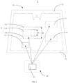
- the projection assembly 20 includes at least one projection light-source 21 capable of projecting onto the at least one projection display region 11. Projection light emitted by the at least one projection light-source 21 is incident onto the at least one projection display region 11 to form a projection image 114.
- the projection image 114 has a virtual-image plane TB10.
- the eyebox EB1 has an eyebox plane EB10 through which the projection image 114 is observed via the at least one projection display region 11.
- the eyebox plane EB10 includes multiple eyebox sub-planes EB11 from low to high.
- the virtual-image plane TB10 includes multiple virtual-image sub-planes TB11 that are from high to low and corresponding to the multiple eyebox sub-planes EB11.
- the projection assembly 20 includes at least one projection light-source 21 projecting onto the at least one projection display region 11.
- One projection light-source 21 is disposed corresponding to one projection display region 11, or one projection light-source 21 is disposed corresponding to multiple projection display regions 11.
- the projection light emitted by the projection light-source 21 is directly incident onto the projection display region 11.
- the projection light emitted by the projection light-source 21 is incident onto the projection display region 11 through a reflection device.
- the projection light emitted by the projection light-source 21 is incident onto the projection display region 11 to form the projection image 114.
- the projection image 114 is displayed in front of the laminated glass 10.
- the projection image 114 has the virtual-image plane TB10 located outside the vehicle when the laminated glass 10 is mounted on the vehicle.
- the forward tilted angle of the upper virtual-image plane TB112 is larger and the forward tilted angle of the lower virtual-image plane TB113 is larger, the discrete distribution degree of the multiple theoretical wedge angles required by the projection display region 11 for eliminating the secondary image is smaller.
- the forward tilted angle may be adjusted by the projection assembly 20, for example, the forward tilted angle of the upper virtual-image plane TB112 and the forward tilted angle of the lower virtual-image plane TB113 can be set by adjusting a tilted angle of a curved surface of a mirror and a titled angle of a surface of a picture generation unit (PGU) in the projection assembly 20.
- PGU picture generation unit
- the forward tilted angle of the upper virtual-image plane TB112 and/or the lower virtual-image plane TB113 of each of the at least one virtual-image sub-plane TB11 is greater than or equal to 45°, or greater than or equal to 60°, or greater than or equal to 75°, or equal to 90° (being flush with the ground), which can significantly reduce the secondary image phenomenon in the projection display region 11.
- the forward tilted angle of the upper virtual-image plane TB112 and/or the lower virtual-image plane TB113 of each of the at least one virtual-image sub-plane TB11 is greater than 90° and less than or equal to 95°.
- the effect of the head-up display system 1 in eliminating the secondary images corresponding to the multiple eyebox sub-planes EB11 is better, that is, the projection images 114 observed at various heights by the driver in the cab is sharper, thereby improving the driving experience.
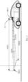
- FIG. 6 two eyebox sub-planes EB11 located at the highest and the lowest positions among the multiple eyebox sub-planes EB11 and two corresponding virtual-image sub-planes TB11 are illustrated.
- dashed-line boxes represent scatter distribution outlines of multiple theoretical wedge angles corresponding to no projected secondary image when the corresponding two virtual-image sub-planes TB11 are observed from the two eyebox sub-planes EB11 located at the highest and the lowest positions on condition that the two virtual-image sub-planes TB11 are not tilted forward.
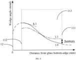
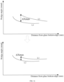
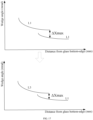
- L0 in FIG. 8 represents a variation line of the wedge angle of each projection display region 11 in the section 113 with the distance from the glass bottom-edge 12 of the laminated glass 10.
- K1 represents a tangent to L0 at a certain point, and a slope of the tangent indicates an absolute value of the ROC of the wedge angle decreasing at the point. If the maximum ROC of the wedge angle in the section 113 is too large, the production and manufacturing difficulty of the laminated glass 10 and production cost of the laminated glass 10 may be increased, which is not conductive to production efficiency of the laminated glass 10, thereby affecting the production efficiency of the laminated glass 10.
- the maximum ROC of the wedge angle in the section 113 may not be suitable to be too large.
- the maximum ROC of continuous non-linear monotonic decrease of the wedge angle in the direction from the lower edge 112 to the upper edge 111 in the section 113 satisfies: ROC ⁇ 0.3 mrad/100 mm.
- the maximum ROC of continuous non-linear monotonic decrease of the wedge angle in the direction from the lower edge 112 to the upper edge 111 in the section 113 satisfies: ROC ⁇ 0.2 mrad/100 mm.
- the angle between any two adjacent virtual-image sub-planes TB11 of the multiple virtual-image sub-planes TB11 is less than or equal to 15°, preferably, less than or equal to 10°, more preferably, less than or equal to 5°, and even more preferably, less than or equal to 2°.
- a virtual-image sub-plane TB11 located right in the middle of the multiple virtual-image sub-planes TB11 is taken as an interface.
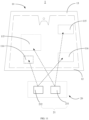
- the at least one projection light-source 21 includes at least one first projection light-source 211 and at least one second projection light-source 212.
- the at least one first projection light-source 211 is incident onto the first projection-display-region 115.
- the at least one second projection light-source 212 is incident onto the second projection-display-region 116.
- the wedge angle in the projection display region 11 may be provided by the first transparent substrate 14 and/or the second transparent substrate 15 and the intermediate adhesive layer 16.
- the first transparent substrate 14 and/or the second transparent substrate 15 have a wedge angle in the projection display region 11
- the intermediate adhesive layer 16 has a wedge angle in the projection display region 11
- a sum of the wedge angle of the first transparent substrate 14 and/or the second transparent substrate 15 in the projection display region 11 and the wedge angle of the intermediate adhesive layer 16 in the projection display region 11 is equal to the wedge angle of the projection display region 11.
- the wedge angle of the first transparent substrate 14 and/or the second transparent substrate 15 is set to be a constant wedge angle.
- a virtual-image plane TB10 that is tilted towards a direction in which a corresponding virtual-image sub-plane TB11 of the virtual-image plane TB10 is observed from an eyebox sub-plane EB11 of the eyebox plane EB10 is designed, according to a projection image observed by the observer inside the vehicle through each of the at least one projection display region 11.
- the eyebox plane EB10 includes multiple eyebox sub-planes EB11 sequentially from low to high.
- the virtual-image plane TB10 includes multiple virtual-image sub-planes TB11 sequentially from high to low.
- Each virtual-image sub-plane TB11 corresponds to one eyebox sub-plane EB11.
- the eyebox plane EB10 includes multiple eyebox sub-planes EB11 sequentially from low to high.
- the virtual-image plane TB10 includes multiple virtual-image sub-planes TB11 sequentially from high to low.
- Each virtual-image sub-plane TB11 corresponds to one eyebox sub-plane EB10.
- the eyebox plane EB10 is used for simulating a plane on which the observer eye is located when the observer sits in a cab of the vehicle.
- the multiple eyebox sub-planes EB11 are used for simulating that the observer eye is at different heights, that is, the multiple eyebox sub-planes EB11 are used for simulating different viewing angles of the observer.
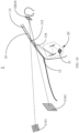
- the upper virtual-image plane TB112 of the virtual-image sub-plane TB11 is tilted towards the direction in which the corresponding virtual-image sub-plane TB11 is observed from the eyebox sub-plane EB11, that is, the projection image 114 is locally tilted forward. Therefore, a distance between the upper virtual-image plane TB112 and the eyebox sub-plane EB11 corresponding to the virtual-image sub-plane TB11 is increased, thereby reducing the theoretical wedge angle required for eliminating the secondary image corresponding to the upper virtual-image plane TB112.
- the local discrete distribution degree of the multiple theoretical wedge angles of the projection display region 11 is reduced, so that the distribution of the multiple theoretical wedge angles is converged towards the first theoretical wedge-angle fitting line L1, that is, a local range of the multiple theoretical wedge angles is reduced.
- each virtual-image sub-plane TB11 designed is a flat plane (referring to (A) in FIG. 4 ) or a curved plane (referring to (B) and (C) in FIG. 4 ).
- a connecting line is drawn between a central point of each eyebox sub-plane EB11 and a central point of the corresponding virtual-image sub-plane TB11, and a plane that passes through the connecting line and is perpendicular to the ground is taken as a primary-optical-axis plane.
- An intersecting line of the primary-optical-axis plane and the corresponding virtual-image sub-plane TB11 has an upper point and a lower point.
- an observation lattice EB111 of m ⁇ n is selected on each eyebox sub-plane EB11, where m ⁇ 1 and is a natural number, and n ⁇ 1 and is a natural number.
- m may be, but is not limited to, 3, 5, or 8, etc.
- n may be, but is not limited to, 3, 5, or 8, etc.
- a virtual-image lattice TB111 of i ⁇ j is selected on each virtual-image sub-plane TB11, where i ⁇ 1 and is a natural number, and j ⁇ 1 and is a natural number.
- i may be, but is not limited to, 3, 5, or 8, etc.
- j may be, but is not limited to, 3, 5, or 8, etc.
- the wedge angle of the laminated glass 10 at a certain distance from the glass bottom-edge 12 is suitable to have one value. Therefore, it is necessary to appropriately select wedge angles at each incident point on the laminated glass 10 to reduce the secondary image phenomenon.
- the wedge angle of the laminated glass 10 in the projection display region 11 is less deviated from the multiple theoretical wedge angles. Therefore, the projected secondary image phenomenon projected onto the projection display region 11 of the laminated glass 10 is reduced, so as to improve the imaging quality of the laminated glass 10.
- different weights can be set to reflect to the corresponding theoretical wedge angle scatters.
- the number of the multiple eyebox sub-planes EB11 is three, fitting weights of theoretical wedge angles corresponding to the multiple eyebox sub-planes EB11 with corresponding height distributions from high to low may be set as 1: 1: 1 (that is, eyebox sub-planes EB11 with various heights have the same weight), 3: 2: 2 (that is, an eyebox sub-plane EB11 with the highest height has a heavier weight), 2: 2: 3 (that is, an eyebox sub-plane EB11 with the lowest height has a heavier weight), 2: 3: 2 (that is, an eyebox sub-plane EB11 in the middle has a heavier weight).
- the wedge angle of the laminated glass 10 in the corresponding projection display region 11 is determined according to the first theoretical wedge-angle fitting line L1, so as to reduce the projected secondary image phenomenon of the laminated glass 10 in the projection display region 11 observed from the eyebox plane EB10. Specifically, by selecting and designing the virtual-image plane TB10, distribution of the multiple theoretical wedge angles of the projection display region 11 on the laminated glass 10 can be calculated, and the first theoretical wedge-angle fitting line L1 corresponding to the projection display region 11 can be fitted, so that the wedge angle of the laminated glass 10 in the corresponding projection display region 11 can be determined.
- the local discrete distribution degree of the multiple theoretical wedge angles required for eliminating the secondary image corresponding to the region of the projection display region 11 is reduced, so that the distribution of the multiple theoretical wedge angles is converged towards the first theoretical wedge-angle fitting line L1, that is, the local range of the multiple theoretical wedge angles is reduced, and thus the effect of the head-up display system 1 in eliminating the secondary image is improved.
- the upper virtual-image plane TB112 and/or the lower virtual-image plane TB113 of each of the at least one virtual-image sub-plane TB11 is approximately tiled on the ground, so that the driver can feel a better ground feel and augmented reality when the driver observes the projection image 114, thereby improving driving experience.
- the forward tilted angle ⁇ 0 of each of at least one virtual-image sub-plane TB11 of the multiple virtual-image sub-planes TB11 is greater than or equal to 45°, or greater than or equal to 60°, or greater than or equal to 75°, or equal to 90° (being flush with the ground), so that the whole projection image 114 can be tilted forward, and the secondary image phenomenon in the projection display region 11 can be significantly reduced.
- the forward tilted angle ⁇ 0 of each of at least one virtual-image sub-plane is greater than 90° and less than or equal to 95°.
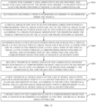
- Designing the virtual-image plane TB10 that is tilted towards the direction in which the corresponding virtual-image sub-plane TB11 of the virtual-image plane TB10 is observed from the eyebox sub-plane EB11 of the eyebox plane EB10, according to the projection image 114 observed by the observer inside the vehicle through each of the at least one projection display region 11, includes the following.
- VID1 > VID2, thereby reducing the projected secondary image.
- an angle between a connecting line of a central point of the eyebox sub-plane EB11 and a central point of the corresponding virtual-image sub-plane TB11 and the ground is a look down angle LDA.
- the look down angle LDA is a negative value, otherwise a positive value.
- the local discrete distribution degree of the multiple theoretical wedge angles required for eliminating the secondary image in the projection display region 11 corresponding to the multiple virtual-image sub-planes TB11 becomes larger and larger from the interface upwards, and the local discrete distribution degree of the multiple theoretical wedge angles required for eliminating the projected secondary image in the projection display region 11 corresponding to the multiple virtual-image sub-planes TB11 also becomes larger and larger from the interface downwards.
- the angle between any adjacent two of the multiple virtual-image sub-planes TB11 is less than or equal to 15°, preferably, less than or equal to 10°, more preferably, less than or equal to 5°, and even more preferably, less than or equal to 2°, thereby improving the driving experience.
- the maximum deviation ⁇ Xmax is greater than 0.15 mrad, it is necessary to adjust the distance between the eyebox plane EB10 and a virtual-image plane TB10 corresponding to any one of the two adjacent first theoretical wedge-angle fitting lines L1, so that the maximum deviation ⁇ Xmax of one of the two adjacent first theoretical wedge-angle fitting lines L1 designed and the second theoretical wedge-angle fitting line L2 adjusted is adjusted to be less than or equal to 0.15 mrad, or less than or equal to 0.10 mrad, or less than or equal to 0.08 mrad, or less than or equal to 0.05 mrad.
- a distance between the eyebox plane EB10 and a virtual-image plane TB10 corresponding to one of the two adjacent first theoretical wedge-angle fitting lines L1 is adjusted.
- the distance between the virtual-image plane TB10 corresponding to one of the two adjacent first theoretical wedge-angle fitting lines L1 and the eyebox plane EB10 may be increased, and/or the distance between the virtual-image plane TB10 corresponding to the other of the two first theoretical wedge-angle fitting lines L1 and the eyebox plane EB10 may be decreased, so that the two adjacent first theoretical wedge-angle fitting lines L1 are closer to the design target.
- the multiple theoretical wedge angles calculated by means of the calculation method in the above implementation can be fitted to a fitting line closer to the design target.
- a wedge angle of the laminated glass 10 in a corresponding first projection-display-region 115 or a corresponding second projection-display-region 116 is determined according to the second theoretical wedge-angle fitting line L2.
- the at least one projection display region 11 includes at least one first projection-display-region 115 and at least one second projection-display-region 116.
- At least two first theoretical wedge-angle fitting lines L1 of wedge angles with distances from incident points to the glass bottom-edge 12 are obtained by fitting.
- a maximum deviation ⁇ Xmax of any two adjacent first theoretical wedge-angle fitting lines L1 is greater than 0.2 mrad, after determining the wedge angle of the laminated glass 10 in the corresponding projection display region 11 according to the first theoretical wedge-angle fitting line L1, the design method for a head-up display system 1 further includes the following.
- a distance between the eyebox plane EB10 and a virtual-image plane TB10 corresponding to one of the two adjacent first theoretical wedge-angle fitting lines L1 is adjusted.
- a third theoretical wedge-angle fitting line L3 of wedge angles with distances from incident points to the glass bottom-edge 12 is obtained by fitting, according to the multiple new theoretical wedge angles and distances from incident points corresponding to the multiple new theoretical wedge angles to the glass bottom-edge 12.
- a wedge angle of the laminated glass 10 in a corresponding first projection-display-region 115 or a corresponding second projection-display-region 116 is determined, according to the third theoretical wedge-angle fitting line L3.
- the overall slope of the first theoretical wedge-angle fitting line L1 and the third theoretical wedge-angle fitting line L3 is reduced, thereby reducing the overall ROC of the wedge angle of the laminated glass 10 and reducing the production difficulty of the laminated glass 10.
- the maximum local range ⁇ WU of the collection of the multiple theoretical wedge angles refers to the maximum among collected local ranges, where a collected local range is a difference between the maximum and the minimum in a collection of multiple theoretical wedge angles at a certain position where the distance from the glass bottom-edge 12 of the laminated glass 10 is X.
- the overall range ⁇ CU of the collection of the multiple theoretical wedge angles refers to a difference between the maximum and the minimum in the collection of all theoretical wedge angles.
- the at least one projection display region 11 includes one first projection-display-region 115.
- the first projection-display-region 115 corresponds to AR-HUD and has a projection display distance of 10000 mm.
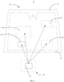
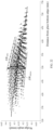
- An observation lattice EB111 of m ⁇ n on each of the three eyebox sub-planes EB11 is a lattice of 5 ⁇ 3 (see FIG. 19 ).
- a virtual-image lattice TB 111 of i ⁇ j on each of the three virtual-image sub-planes TB11 in a one-to-one correspondence with the three eyebox sub-planes EB11 is a lattice of 5 ⁇ 3.
- EB_Rm represents the points on the perpendicular bisector of the middle eyebox sub-plane EB11
- RiCj represents the points on the corresponding virtual-image sub-plane TB11
- a scatter distribution law of the theoretical wedge angles corresponding to no secondary image when the virtual-image sub-plane TB11 is observed from the perpendicular bisector of each of the other eyebox sub-planes EB11 in the first embodiment is the same as that in FIG.
- a distribution of scatters of theoretical wedge angles corresponding to no secondary image when the virtual-image sub-plane TB11 is observed from points on a perpendicular bisector of the eyebox sub-plane EB11 tends to be more converged than in the first embodiment towards the dashed-line segments located in the dashed-line boxes.
- a dashed-line segment in each dashed-line box represents a connecting line of multiple theoretical wedge angles corresponding to no secondary image when a central point of the virtual-image sub-plane TB11 is observed from points on a perpendicular bisector of the eyebox sub-plane EB11.
- a secondary-image value represents the severity of the projected secondary image, and the secondary-image value of 0 represents no projected secondary image.
- the maximum local range ⁇ W is proportional to the secondary-image value. When ⁇ W is smaller, the secondary-image value is smaller.
- a change of ⁇ W corresponds to a change of the secondary-image value.
- the change of ⁇ W / ⁇ C is 21.1%.
- ⁇ W / ⁇ C reflects the improvement of the secondary-image value corresponding to the variable wedge angle adopted relative to the constant wedge angle.
- the change of ⁇ W / ⁇ C is 21.1%, which means that the second embodiment is more suitable for adopting the variable wedge angle than the first embodiment, and the improvement rate is 21.1%.
Landscapes
- Physics & Mathematics (AREA)
- Engineering & Computer Science (AREA)
- General Physics & Mathematics (AREA)
- Optics & Photonics (AREA)
- Chemical & Material Sciences (AREA)
- Combustion & Propulsion (AREA)
- Transportation (AREA)
- Mechanical Engineering (AREA)
- Instrument Panels (AREA)
Applications Claiming Priority (1)
| Application Number | Priority Date | Filing Date | Title |
|---|---|---|---|
| PCT/CN2022/105863 WO2023103381A1 (zh) | 2022-07-15 | 2022-07-15 | 抬头显示系统及抬头显示系统的设计方法 |
Publications (2)
| Publication Number | Publication Date |
|---|---|
| EP4538771A1 true EP4538771A1 (de) | 2025-04-16 |
| EP4538771A4 EP4538771A4 (de) | 2025-08-06 |
Family
ID=86729575
Family Applications (1)
| Application Number | Title | Priority Date | Filing Date |
|---|---|---|---|
| EP22902816.2A Pending EP4538771A4 (de) | 2022-07-15 | 2022-07-15 | Head-up-anzeigesystem und entwurfsverfahren für ein head-up-anzeigesystem |
Country Status (6)
| Country | Link |
|---|---|
| US (1) | US20250189787A1 (de) |
| EP (1) | EP4538771A4 (de) |
| JP (1) | JP2025524646A (de) |
| KR (1) | KR20250021387A (de) |
| CN (1) | CN119522393A (de) |
| WO (1) | WO2023103381A1 (de) |
Family Cites Families (10)
| Publication number | Priority date | Publication date | Assignee | Title |
|---|---|---|---|---|
| DE102007059323A1 (de) * | 2007-12-07 | 2009-06-10 | Saint-Gobain Sekurit Deutschland Gmbh & Co. Kg | Windschutzscheibe mit einem HUD-Sichtfeld |
| PL3079901T3 (pl) * | 2013-12-12 | 2021-02-08 | Saint-Gobain Glass France | Folia termoplastyczna dla szyby ze szkła wielowarstwowego z nieliniowo-ciągłą wkładką klinową w kierunku pionowym i poziomym |
| JP2016102966A (ja) * | 2014-11-28 | 2016-06-02 | アイシン・エィ・ダブリュ株式会社 | 虚像表示装置 |
| US20170285339A1 (en) * | 2016-04-04 | 2017-10-05 | Solutia Inc. | Interlayers having enhanced optical performance |
| JP6717264B2 (ja) * | 2017-06-08 | 2020-07-01 | 株式会社Jvcケンウッド | 虚像表示装置、中間像形成部および画像表示光生成ユニット |
| WO2020171045A1 (ja) * | 2019-02-21 | 2020-08-27 | 日本精機株式会社 | ヘッドアップディスプレイ装置、表示制御装置、及び表示制御プログラム |
| CN213987029U (zh) * | 2020-08-21 | 2021-08-17 | 未来(北京)黑科技有限公司 | 双层成像抬头显示装置、抬头显示系统及交通设备 |
| CN113968053B (zh) * | 2021-09-27 | 2024-01-30 | 福耀玻璃工业集团股份有限公司 | 用于抬头显示的夹层玻璃及抬头显示系统 |
| CN114200675B (zh) * | 2021-12-09 | 2022-11-29 | 奇瑞汽车股份有限公司 | 显示方法、装置、抬头显示系统和车辆 |
| CN114740627B (zh) * | 2022-05-25 | 2023-07-25 | 福耀玻璃工业集团股份有限公司 | 抬头显示系统及其设计方法 |
-
2022
- 2022-07-15 EP EP22902816.2A patent/EP4538771A4/de active Pending
- 2022-07-15 WO PCT/CN2022/105863 patent/WO2023103381A1/zh not_active Ceased
- 2022-07-15 KR KR1020257001699A patent/KR20250021387A/ko active Pending
- 2022-07-15 CN CN202280098081.6A patent/CN119522393A/zh active Pending
- 2022-07-15 JP JP2025501516A patent/JP2025524646A/ja active Pending
-
2025
- 2025-01-15 US US19/022,614 patent/US20250189787A1/en active Pending
Also Published As
| Publication number | Publication date |
|---|---|
| KR20250021387A (ko) | 2025-02-12 |
| EP4538771A4 (de) | 2025-08-06 |
| US20250189787A1 (en) | 2025-06-12 |
| WO2023103381A1 (zh) | 2023-06-15 |
| CN119522393A (zh) | 2025-02-25 |
| JP2025524646A (ja) | 2025-07-30 |
Similar Documents
| Publication | Publication Date | Title |
|---|---|---|
| US10061126B2 (en) | Optical device | |
| EP4513250A1 (de) | Head-up-anzeigesystem und entwurfsverfahren dafür | |
| AU566375B2 (en) | Rearview mirror | |
| US10788665B2 (en) | Projection optical system and head-up display device | |
| US6686850B2 (en) | System of pitch attitude symbols | |
| CN112313558A (zh) | 用于运行机动车用的视场显示装置的方法 | |
| EP4538771A1 (de) | Head-up-anzeigesystem und entwurfsverfahren für ein head-up-anzeigesystem | |
| JP2019082601A (ja) | 表示システム、及び移動体 | |
| CN114740627B (zh) | 抬头显示系统及其设计方法 | |
| CN114839780B (zh) | 抬头显示系统及抬头显示系统的设计方法 | |
| CN119213347B (zh) | 抬头显示系统及抬头显示系统的设计方法 | |
| US20110228414A1 (en) | Reflecting device with wide vision angle, reduced distortion and anamorphosis and reduced doubling of reflected images, particularly for vehicles | |
| EP3757657B1 (de) | Head-up-anzeige und mobiles objekt | |
| CN217718280U (zh) | 一种抬头显示系统及汽车 | |
| US7746554B2 (en) | Lenticular lens, light-diffusing sheet, and projection screen | |
| US10852539B2 (en) | Projection optical system, head-up display device, and vehicle | |
| JP7128448B2 (ja) | ヘッドアップディスプレイ装置 | |
| US9340160B2 (en) | Low distortion convex mirror for a vehicle rearview mirror assembly | |
| JP2021085913A (ja) | 光学部材 | |
| JP2023160300A (ja) | ヘッドアップディスプレイ装置 | |
| WO2023204198A1 (ja) | ヘッドアップディスプレイ装置 | |
| CN117233966A (zh) | 一种抬头显示重影的处理方法和装置 | |
| CN117471685A (zh) | 显示装置、抬头显示装置和交通工具 |
Legal Events
| Date | Code | Title | Description |
|---|---|---|---|
| STAA | Information on the status of an ep patent application or granted ep patent |
Free format text: STATUS: THE INTERNATIONAL PUBLICATION HAS BEEN MADE |
|
| PUAI | Public reference made under article 153(3) epc to a published international application that has entered the european phase |
Free format text: ORIGINAL CODE: 0009012 |
|
| STAA | Information on the status of an ep patent application or granted ep patent |
Free format text: STATUS: REQUEST FOR EXAMINATION WAS MADE |
|
| 17P | Request for examination filed |
Effective date: 20250113 |
|
| AK | Designated contracting states |
Kind code of ref document: A1 Designated state(s): AL AT BE BG CH CY CZ DE DK EE ES FI FR GB GR HR HU IE IS IT LI LT LU LV MC MK MT NL NO PL PT RO RS SE SI SK SM TR |
|
| A4 | Supplementary search report drawn up and despatched |
Effective date: 20250709 |
|
| RIC1 | Information provided on ipc code assigned before grant |
Ipc: G02B 27/01 20060101AFI20250703BHEP Ipc: B60J 1/02 20060101ALI20250703BHEP |
|
| DAV | Request for validation of the european patent (deleted) | ||
| DAX | Request for extension of the european patent (deleted) |