EP4538977A1 - Codierungsvorrichtung, decodierungsvorrichtung, codierungsverfahren und decodierungsverfahren - Google Patents
Codierungsvorrichtung, decodierungsvorrichtung, codierungsverfahren und decodierungsverfahren Download PDFInfo
- Publication number
- EP4538977A1 EP4538977A1 EP23819847.7A EP23819847A EP4538977A1 EP 4538977 A1 EP4538977 A1 EP 4538977A1 EP 23819847 A EP23819847 A EP 23819847A EP 4538977 A1 EP4538977 A1 EP 4538977A1
- Authority
- EP
- European Patent Office
- Prior art keywords
- vertex
- triangle
- information
- encoding
- mode
- Prior art date
- Legal status (The legal status is an assumption and is not a legal conclusion. Google has not performed a legal analysis and makes no representation as to the accuracy of the status listed.)
- Pending
Links
Images






















Classifications
-
- G—PHYSICS
- G06—COMPUTING OR CALCULATING; COUNTING
- G06T—IMAGE DATA PROCESSING OR GENERATION, IN GENERAL
- G06T9/00—Image coding
- G06T9/001—Model-based coding, e.g. wire frame
-
- G—PHYSICS
- G06—COMPUTING OR CALCULATING; COUNTING
- G06T—IMAGE DATA PROCESSING OR GENERATION, IN GENERAL
- G06T9/00—Image coding
Definitions
- the present disclosure relates to, for example, an encoding device.
- PTL 1 proposes a method and a device for encoding and decoding three-dimensional mesh data.
- An object of the present disclosure is to improve processing of encoding three-dimensional data and the like.
- An encoding device includes: memory; and a circuit accessible to the memory, in which, in operation, the circuit: when a first triangle satisfies a condition, selects a mode for encoding a current vertex to be encoded of a second triangle from among a first set of modes including a normal mode that uses the first triangle to encode the current vertex; when the first triangle does not satisfy the condition, selects the mode from among a second set of modes including an exception mode that uses a third triangle different from the first triangle and the second triangle to encode the current vertex; and encodes the current vertex according to the mode selected.
- a three-dimensional mesh is used in computer graphic images.
- a three-dimensional mesh is constituted of vertex information indicating a position of each of a plurality of vertexes in a three-dimensional space, connection information indicating a connection relationship among the plurality of vertexes, and attribute information indicating an attribute of each vertex or each face.
- Each face is constructed according to the connection relationship among a plurality of vertexes.
- Various computer graphic images can be expressed by such three-dimensional meshes.
- an encoding device reduces a coding amount by predicting position information of a vertex being an encoding object using position information of an encoded vertex and encoding a difference with respect to the prediction. More specifically, for example, the encoding device encodes the vertexes of the second triangle adjacent to the first triangle by referring to the first triangle as a reference triangle, thereby reducing the code amount.
- an encoding device of Example 1 includes: memory; and a circuit accessible to the memory, in which, in operation, the circuit: when a first triangle satisfies a condition, selects a mode for encoding a current vertex to be encoded of a second triangle from among a first set of modes including a normal mode that uses the first triangle to encode the current vertex; when the first triangle does not satisfy the condition, selects the mode from among a second set of modes including an exception mode that uses a third triangle different from the first triangle and the second triangle to encode the current vertex; and encodes the current vertex according to the mode selected.
- an encoding device of Example 3 may be the encoding device of Example 1 or 2, in which the third triangle shares an edge with the second triangle.
- an encoding device of Example 4 may be the encoding device of any of Examples 1 to 3, in which the third triangle shares a vertex with the first triangle.
- an encoding device of Example 5 may be the encoding device of any of Examples 1 to 4, in which each vertex of the third triangle has been encoded.
- an encoding device of Example 6 may be the encoding device of any of Examples 1 to 5, in which each edge of the third triangle has connectivity.
- an encoding device of Example 7 may be the encoding device of any of Examples 1 to 4, in which the third triangle has a dummy vertex.
- an encoding device of Example 8 may be the encoding device of any of Examples 1 to 7, in which the exception mode includes sub-modes, and when selecting the exception mode as the mode for encoding the current vertex, the circuit further selects a sub-mode for encoding the current vertex from among the sub-modes.
- the encoding device and the decoding device may share information of the sub-mode for encoding the current vertex to be encoded according to the parameter. Therefore, it may be possible to apply the same sub-mode to the encoding and the decoding according to the parameter.
- an encoding device of Example 10 may be the encoding device of Example 8 or 9, in which the circuit determines the third triangle according to the sub-mode selected.
- selecting a sub-mode from among a plurality of sub-modes may make it possible to select a third triangle suitable for encoding. Therefore, it may be possible to efficiently encode the current vertex to be encoded by using a third triangle suitable for the encoding.
- an encoding device of Example 11 may be the encoding device of any of Examples 8 to 10, in which the circuit determines a vertex of the third triangle according to the sub-mode selected.
- selecting a sub-mode from among a plurality of sub-modes may make it possible to select vertexes of a third triangle suitable for encoding. Therefore, it may be possible to efficiently encode the current vertex to be encoded by using a third triangle suitable for the encoding.
- an encoding device of Example 12 may be the encoding device of any of Examples 1 to 11, in which the condition includes that each vertex of the first triangle has been encoded.
- an encoding device of Example 13 may be the encoding device of any of Examples 1 to 12, in which the condition includes that each edge of the first triangle has connectivity.
- an encoding device of Example 14 may be the encoding device of any of Examples 1 to 13, in which, when encoding the current vertex according to the exception mode, the circuit encodes an angle indicating the current vertex using the third triangle.
- a decoding device of Example 15 includes: memory; and a circuit accessible to the memory, in which, in operation, the circuit: when a first triangle satisfies a condition, selects a mode for decoding a current vertex to be decoded of a second triangle from among a first set of modes including a normal mode that uses the first triangle to decode the current vertex; when the first triangle does not satisfy the condition, selects the mode from among a second set of modes including an exception mode that uses a third triangle different from the first triangle and the second triangle to decode the current vertex; and decodes the current vertex according to the mode selected.
- the first triangle when the first triangle does not satisfy the condition, it may be possible to use the third triangle different from the first triangle to decode the vertexes of the second triangle. Therefore, it may be possible to decode the vertexes of the second triangle by using a reference triangle suitable for the decoding.
- a decoding device of Example 16 may be the decoding device of Example 15, in which the third triangle shares an edge with the first triangle.
- a decoding device of Example 17 may be the decoding device of Example 15 or 16, in which the third triangle shares an edge with the second triangle.
- a decoding device of Example 19 may be the decoding device of any of Examples 15 to 18, in which each vertex of the third triangle has been decoded.
- a decoding device of Example 22 may be the decoding device of any of Examples 15 to 21, in which the exception mode includes sub-modes, and when selecting the exception mode as the mode for decoding the current vertex, the circuit further selects a sub-mode for decoding the current vertex from among the sub-modes.
- a decoding device of Example 23 may be the decoding device of Example 22, in which the circuit decodes a parameter indicating the sub-mode selected.
- the encoding device and the decoding device may share information of the sub-mode for decoding the current vertex to be decoded according to the parameter. Therefore, it may be possible to apply the same sub-mode to the encoding and the decoding according to the parameter.
- a decoding device of Example 25 may be the decoding device of any of Examples 22 to 24, in which the circuit determines a vertex of the third triangle according to the sub-mode selected.
- a three-dimensional mesh is a set of a plurality of faces and indicates, for example, a three-dimensional object.
- a three-dimensional mesh is mainly constituted of vertex information, connection information, and attribute information.
- a three-dimensional mesh may be expressed as a polygon mesh or a mesh.
- a three-dimensional mesh may have a temporal change.
- a three-dimensional mesh may include metadata related to vertex information, connection information, and attribute information or other additional information.
- Vertex information is information indicating a vertex.
- vertex information indicates a position of a vertex in a three-dimensional space.
- a vertex corresponds to a vertex of a face that constitutes a three-dimensional mesh.
- Vertex information may be expressed as "geometry”.
- vertex information may also be expressed as position information.
- encoding information may mean including information in a bitstream.
- encoding information in a bitstream may mean encoding the information and generating a bitstream that includes the encoded information.
- decoding information may mean acquiring information from a bitstream.
- decoding information from a bitstream may mean decoding the bitstream and acquiring information included in the bitstream.
- an ordinal number such as first, second, or the like may be affixed to a constituent element or the like. Such ordinal numbers may be replaced as necessary. In addition, an ordinal number may be newly affixed to or removed from a constituent element or the like. Furthermore, the ordinal numbers may be affixed to elements in order to identify the elements and may not correspond to any meaningful order.
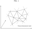
- FIG. 1 is a conceptual diagram illustrating a three-dimensional mesh according to the present embodiment.
- the three-dimensional mesh is constituted of a plurality of faces.
- each face is a triangle. Vertexes of the triangles are determined in a three-dimensional space.
- a three-dimensional mesh indicates a three-dimensional object.
- Each face may have a color or an image.
- Attribute information may be associated with a vertex or associated with a face. Attribute information associated with a vertex may be expressed as "attribute per point”. Attribute information associated with a vertex may indicate an attribute of the vertex itself or indicate an attribute of a face connected to the vertex.
- attribute information information on a color, an image, a moving image, and the like to be used as attribute information may be expressed as "parametric space".
- a texture is reflected in a three-dimensional object based on such attribute information.
- a colored three-dimensional object is formed in a three-dimensional space based on vertex information, connection information, and attribute information.
- attribute information is associated with a vertex or a face in the description given above, alternatively, attribute information may be associated with an edge.
- mapping enables a two-dimensional image to be used as attribute information to be separated from the three-dimensional mesh.
- the two-dimensional image may be encoded based on an image encoding system or a video encoding system.
- network 300 may be replaced with a recording medium such as a DVD (digital versatile disc), a BD (Blu-Ray Disc (registered trademark)), or the like.
- a recording medium such as a DVD (digital versatile disc), a BD (Blu-Ray Disc (registered trademark)), or the like.
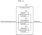
- Attribute information encoder 103 is an electric circuit which encodes attribute information.
- attribute information encoder 103 encodes attribute information into a bitstream according to a format defined with respect to the attribute information.
- Variable-length coding or fixed length coding may be used for encoding vertex information, connection information, and attribute information.
- the variable-length coding may accommodate Huffman coding, context-adaptive binary arithmetic coding (CABAC), or the like.
- Vertex information encoder 101, connection information encoder 102, and attribute information encoder 103 may be integrated. Alternatively, each of vertex information encoder 101, connection information encoder 102, and attribute information encoder 103 may be more finely segmentalized into a plurality of constituent elements.
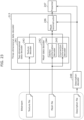
- FIG. 6 is a block diagram illustrating another configuration example of encoding device 100 according to the present embodiment.
- encoding device 100 includes preprocessor 104 and postprocessor 105.
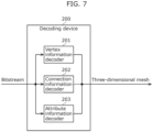
- Attribute information decoder 203 is an electric circuit which decodes attribute information. For example, attribute information decoder 203 decodes attribute information from a bitstream according to a format defined with respect to the attribute information.
- Vertex information decoder 201, connection information decoder 202, and attribute information decoder 203 may be integrated. Alternatively, each of vertex information decoder 201, connection information decoder 202, and attribute information decoder 203 may be more finely segmentalized into a plurality of constituent elements.
- FIG. 8 is a block diagram illustrating another configuration example of decoding device 200 according to the present embodiment.
- decoding device 200 includes preprocessor 204 and postprocessor 205.
- preprocessor 204 may demultiplex, from a bitstream, a sub-bitstream corresponding to vertex information, a sub-bitstream corresponding to connection information, and a sub-bitstream corresponding to attribute information.
- preprocessor 204 may perform variable-length decoding with respect to the bitstream in advance before decoding of vertex information, connection information, and attribute information.
- Postprocessor 205 is an electric circuit which performs processing after the decoding of vertex information, connection information, and attribute information.
- postprocessor 205 may perform transformation processing, demultiplexing, multiplexing, or the like with respect to vertex information, connection information, and attribute information after decoding. More specifically, for example, postprocessor 205 may multiplex vertex information, connection information, and attribute information after decoding into a three-dimensional mesh.
- Vertex information, connection information, and attribute information are encoded and stored in a bitstream. A relationship between these pieces of information and the bitstream will be described below.
- a plurality of portions of the pieces of information may be sequentially stored such as a first portion of vertex information, a first portion of connection information, a first portion of attribute information, a second portion of vertex information, a second portion of connection information, a second portion of attribute information, ...
- the plurality of portions may correspond to a plurality of temporally different portions, correspond to a plurality of spatially different portions, or correspond to a plurality of different faces.
- FIG. 11 is a conceptual diagram illustrating another configuration example of a bitstream according to the present embodiment.
- a bitstream is constituted of a plurality of separable sub-bitstreams and vertex information, connection information, and attribute information are respectively stored in different sub-bitstreams.
- two types of information among vertex information, connection information, and attribute information may be included in one sub-bitstream and the one remaining type of information may be included in another sub-bitstream.
- attribute information such as a two-dimensional image may be stored in a sub-bitstream conforming to an image coding system separately from a sub-bitstream of vertex information and connection information.
- each sub-bitstream may include a plurality of files.
- a plurality of portions of vertex information may be stored in a plurality of files
- a plurality of portions of connection information may be stored in a plurality of files
- a plurality of portions of attribute information may be stored in a plurality of files.
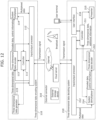
- FIG. 12 is a block diagram illustrating a specific example of the encoding/decoding system according to the present embodiment.
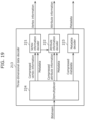
- the encoding/decoding system includes three-dimensional data encoding system 110, three-dimensional data decoding system 210, and external connector 310.
- Three-dimensional data encoding system 110 includes controller 111, input/output processor 112, three-dimensional data encoder 113, three-dimensional data generator 115, and system multiplexer 114.
- Three-dimensional data decoding system 210 includes controller 211, input/output processor 212, three-dimensional data decoder 213, system demultiplexer 214, presenter 215, and user interface 216.
- sensor data is input from a sensor terminal to three-dimensional data generator 115.
- Three-dimensional data generator 115 generates three-dimensional data that is point cloud data, mesh data, or the like from the sensor data and inputs the three-dimensional data to three-dimensional data encoder 113.
- three-dimensional data generator 115 generates vertex information and generates connection information and attribute information which correspond to the vertex information.
- Three-dimensional data generator 115 may process vertex information when generating connection information and attribute information. For example, three-dimensional data generator 115 may reduce a data amount by deleting overlapping vertexes or transform vertex information (position shift, rotation, normalization, or the like). In addition, three-dimensional data generator 115 may render attribute information.
- three-dimensional data generator 115 is a constituent element of three-dimensional data encoding system 110 in FIG. 12 , three-dimensional data generator 115 may be disposed on the outside independent of three-dimensional data encoding system 110.
- a sensor terminal that provides sensor data for generating three-dimensional data may be a mobile object such as an automobile, a flying object such as an airplane, a mobile terminal, a camera, or the like.
- a range sensor such as LIDAR, a millimeter-wave radar, an infrared sensor, or a range finder, a stereo camera, a combination of a plurality of monocular cameras, or the like may be used as the sensor terminal.
- the sensor data may be a distance (position) of an object, a monocular camera image, a stereo camera image, a color, a reflectance, an attitude or an orientation of a sensor, a gyro, a sensing position (GPS information or elevation), a velocity, an acceleration, a time of day of sensing, air temperature, air pressure, humidity, magnetism, or the like.
- the encoding system of three-dimensional data may be an encoding system using geometry or an encoding system using a video codec.
- an encoding system using geometry may also be expressed as a geometry-based encoding system.
- An encoding system using a video codec may also be expressed as a video-based encoding system.
- multiplexed data has a file format for accumulation, a packet format for transmission, or the like.
- ISOBMFF or an ISOBMFF-based system may be used as an accumulation system or a transmission system.
- MPEG-DASH, MMT, MPEG-2 TS Systems, RTP, or the like may be used.
- multiplexed data is output as a transmission signal by input/output processor 112 to external connector 310.
- the multiplexed data may be transmitted as a transmission signal in a wired manner or in a wireless manner.
- the multiplexed data is accumulated in an internal memory or a storage device.
- the multiplexed data may be transmitted via the Internet to a cloud server or stored in an external storage device.
- the transmission or accumulation of the multiplexed data is performed by a method in accordance with a medium for transmission or accumulation such as broadcasting or communication.
- a medium for transmission or accumulation such as broadcasting or communication.
- a communication protocol http, ftp, TCP, UDP, IP, or a combination thereof may be used.
- a pull-type communication scheme may be used or a push-type communication scheme may be used.
- Ethernet (registered trademark), USB, RS-232C, HDMI (registered trademark), a coaxial cable, or the like may be used for wired transmission.
- 3GPP registered trademark
- 3G/4G/5G as specified by IEEE a wireless LAN, Bluetooth, or a millimeter-wave may be used for wireless transmission.
- DVB-T2, DVB-S2, DVB-C2, ATSC 3.0, ISDB-S3, or the like may be used as a broadcasting system.
- sensor data may be input to three-dimensional data generator 115 or system multiplexer 114.
- three-dimensional data or encoded data may be output as-is as a transmission signal to external connector 310 via input/output processor 112.
- the transmission signal output from three-dimensional data encoding system 110 is input to three-dimensional data decoding system 210 via external connector 310.
- a transmission signal is input to input/output processor 212.
- Input/output processor 212 decodes multiplexed data having a file format or a packet format from the transmission signal and inputs the multiplexed data to system demultiplexer 214.
- System demultiplexer 214 acquires encoded data and control information from the multiplexed data and inputs the encoded data and the control information to three-dimensional data decoder 213.
- System demultiplexer 214 may extract other media, reference time information, or the like from the multiplexed data.
- Three-dimensional data decoder 213 corresponds to decoding device 200 illustrated in FIG. 7 and the like. For example, three-dimensional data decoder 213 decodes three-dimensional data from the encoded data based on an encoding system specified in advance. Subsequently, the three-dimensional data is presented to a user by presenter 215.
- additional information such as sensor data may be input to presenter 215.
- Presenter 215 may present three-dimensional data based on the additional information.
- an instruction by the user may be input to user interface 216 from a user terminal.
- presenter 215 may present three-dimensional data based on the input instruction.
- a point cloud is constituted of a plurality of points and has position information which indicates a three-dimensional coordinate position of each point and attribute information which indicates an attribute of each point.
- the position information is also expressed as geometry.
- a type of attribute information may be a color, a reflectance, or the like. Attribute information related to one type may be associated with one point, attribute information related to a plurality of different types may be associated with one point, or attribute information having a plurality of values with respect to a same type may be associated with one point.
- a three-dimensional mesh is constituted of a plurality of edges and a plurality of faces.
- Each point is also expressed as a vertex or a position.
- Each edge corresponds to a line segment which connects two vertexes.
- Each face corresponds to an area enclosed by three or more edges.
- a three-dimensional mesh has position information indicating three-dimensional coordinate positions of vertexes.
- the position information is also expressed as vertex information or geometry.
- a three-dimensional mesh has connection information indicating a relationship among a plurality of vertexes constituting an edge or a face.
- the connection information is also expressed as connectivity.
- a three-dimensional mesh has attribute information indicating an attribute with respect to a vertex, an edge, or a face.
- the attribute information in a three-dimensional mesh is also expressed as a texture.
- attribute information may indicate a color, a reflectance, or a normal vector with respect to a vertex, an edge, or a face.
- An orientation of a normal vector can express a front and a rear of a face.
- An object file or the like may be used as a data file format of mesh data.
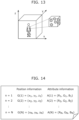
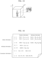
- FIG. 16 is a conceptual diagram illustrating a data file example of the mesh data according to the present embodiment.
- a data file includes pieces of position information G(1) to G(N) and pieces of attribute information A1(1) to A1(N) of N-number of vertexes which constitute a three-dimensional mesh.
- M-number of pieces of attribute information A2(1) to A2(M) are included.
- An item of attribute information need not correspond one-to-one to a vertex and need not correspond one-to-one to a face.
- attribute information need not exist.
- Connection information is indicated by a combination of indexes of vertexes.
- a substantive content of the attribute information may be described in a separate file.
- a pointer with respect to the content may be associated with a vertex, a face, or the like.
- attribute information indicating an image with respect to a face may be stored in a two-dimensional attribute map file.
- a file name of the attribute map and a two-dimensional coordinate value in the attribute map may be described in pieces of attribute information A2(1) to A2(M).
- point cloud data with respect to an arbitrary time point may be expressed as a PCC frame.
- mesh data with respect to an arbitrary time point may be expressed as a mesh frame.
- a PCC frame and a mesh frame may be simply expressed as a frame.
- an area of an object may be limited to a certain range in a similar manner to ordinary video data or need not be limited in a similar manner to map data.
- a density of points or faces may be set in various ways. Sparse point cloud data or sparse mesh data may be used or dense point cloud data or dense mesh data may be used.
- a device, processing, or a syntax for encoding and decoding vertex information of a three-dimensional mesh according to the present disclosure may be applied to the encoding and decoding of a point cloud.
- a device, processing, or a syntax for encoding and decoding a point cloud according to the present disclosure may be applied to the encoding and decoding of vertex information of a three-dimensional mesh.
- a device, processing, or a syntax for encoding and decoding attribute information of a point cloud according to the present disclosure may be applied to the encoding and decoding of connection information or attribute information of a three-dimensional mesh.
- a device, processing, or a syntax for encoding and decoding connection information or attribute information of a three-dimensional mesh according to the present disclosure may be applied to the encoding and decoding of attribute information of a point cloud.
- processing may be commonalized between the encoding and decoding of point cloud data and the encoding and decoding of mesh data. Accordingly, sizes of circuits and software programs can be suppressed.
- three-dimensional data encoder 113 encodes three-dimensional data according to a geometry-based encoding system. Encoding according to the geometry-based encoding system takes a three-dimensional structure into consideration. Furthermore, in encoding according to the geometry-based encoding system, attribute information is encoded using configuration information obtained during encoding of vertex information.
- Vertex information encoder 121 encodes vertex information into compressed vertex information and outputs the compressed vertex information to multiplexer 124 as encoded data.
- vertex information encoder 121 generates metadata of the compressed vertex information and outputs the metadata to multiplexer 124.
- vertex information encoder 121 generates configuration information and outputs the configuration information to attribute information encoder 122.
- Attribute information encoder 122 encodes attribute information into compressed attribute information using the configuration information generated by vertex information encoder 121 and outputs the compressed attribute information to multiplexer 124 as encoded data. In addition, attribute information encoder 122 generates metadata of the compressed attribute information and outputs the metadata to multiplexer 124.
- three-dimensional data encoder 113 encodes three-dimensional data according to a video-based encoding system.
- a plurality of two-dimensional images are generated from three-dimensional data and the plurality of two-dimensional images are encoded according to a video encoding system.
- the video encoding system may be HEVC (high efficiency video coding), VVC (versatile video coding), or the like.
- vertex information and attribute information included in three-dimensional data generated from sensor data are input to metadata generator 133.
- the vertex information and the attribute information are respectively input to vertex image generator 131 and attribute image generator 132.
- the metadata included in the three-dimensional data is input to metadata encoder 123.
- connection information included in three-dimensional data may be handled in a similar manner to attribute information.
- position information may be handled as vertex information.
- Multiplexer 124 multiplexes the compressed vertex information, the metadata of the compressed vertex information, the compressed attribute information, the metadata of the compressed attribute information, and the compressed metadata into a bitstream. In addition, multiplexer 124 inputs the bitstream into a system layer.
- FIG. 21 is a block diagram illustrating another configuration example of three-dimensional data decoder 213 according to the present embodiment.
- three-dimensional data decoder 213 includes vertex information generator 231, attribute information generator 232, video decoder 234, metadata decoder 223, and demultiplexer 224.
- Vertex information generator 231, attribute information generator 232, and video decoder 234 may correspond to vertex information decoder 201, attribute information decoder 203, and the like illustrated in FIG. 8 .
- three-dimensional data decoder 213 decodes three-dimensional data according to a video-based encoding system.
- decoding according to the video-based encoding system a plurality of two-dimensional images are decoded according to a video encoding system and three-dimensional data is generated from the plurality of two-dimensional images.
- the video encoding system may be HEVC (high efficiency video coding), VVC (versatile video coding), or the like.
- a bitstream is input from a system layer into demultiplexer 224.
- Demultiplexer 224 separates compressed vertex information, metadata of the compressed vertex information, compressed attribute information, metadata of the compressed attribute information, and compressed metadata from the bitstream.
- the compressed vertex information, the metadata of the compressed vertex information, the compressed attribute information, and the metadata of the compressed attribute information are input to video decoder 234.
- the compressed metadata is input to metadata decoder 223.
- Video decoder 234 decodes a vertex image according to the video encoding system. In doing so, video decoder 234 decodes the vertex image from the compressed vertex information using the metadata of the compressed vertex information. In addition, video decoder 234 inputs the vertex image into vertex information generator 231. Furthermore, video decoder 234 decodes an attribute image according to the video encoding system. In doing so, video decoder 234 decodes the attribute image from the compressed attribute information using the metadata of the compressed attribute information. In addition, video decoder 234 inputs the attribute image into attribute information generator 232.
- Metadata decoder 223 decodes metadata from the compressed metadata.
- the metadata decoded by metadata decoder 223 includes map information to be used to generate vertex information and to generate attribute information.
- the metadata decoded by metadata decoder 223 may be used to decode the vertex image and to decode the attribute image.
- Vertex information generator 231 reproduces vertex information from the vertex image according to the map information included in the metadata decoded by metadata decoder 223.
- Attribute information generator 232 reproduces attribute information from the attribute image according to the map information included in the metadata decoded by metadata decoder 223.
- FIG. 22 is a conceptual diagram illustrating a specific example of encoding processing according to the present embodiment.
- FIG. 22 illustrates three-dimensional data encoder 113 and description encoder 148.
- three-dimensional data encoder 113 includes two-dimensional data encoder 141 and mesh data encoder 142.
- Two-dimensional data encoder 141 includes texture encoder 143.
- Mesh data encoder 142 includes vertex information encoder 144 and connection information encoder 145.
- Vertex information encoder 144, connection information encoder 145, and texture encoder 143 may correspond to vertex information encoder 101, connection information encoder 102, attribute information encoder 103, and the like illustrated in FIG. 6 .
- two-dimensional data encoder 141 operates as texture encoder 143 and generates a texture file by encoding a texture corresponding to attribute information as two-dimensional data according to an image encoding system or a video encoding system.
- description encoder 148 generates a description file by encoding a description corresponding to metadata such as text data.
- Description encoder 148 may encode a description in the system layer.
- description encoder 148 may be included in system multiplexer 114 illustrated in FIG. 12 .
- FIG. 23 is a conceptual diagram illustrating a specific example of decoding processing according to the present embodiment.
- FIG. 23 illustrates three-dimensional data decoder 213, description decoder 248, and presenter 247.
- three-dimensional data decoder 213 includes two-dimensional data decoder 241, mesh data decoder 242, and mesh reconstructor 246.
- Two-dimensional data decoder 241 includes texture decoder 243.
- Mesh data decoder 242 includes vertex information decoder 244 and connection information decoder 245.
- Vertex information decoder 244, connection information decoder 245, texture decoder 243, and mesh reconstructor 246 may correspond to vertex information decoder 201, connection information decoder 202, attribute information decoder 203, postprocessor 205, and the like illustrated in FIG. 8 .
- Presenter 247 may correspond to presenter 215 and the like illustrated in FIG. 12 .
- two-dimensional data decoder 241 operates as texture decoder 243 and decodes a texture corresponding to attribute information from a texture file as two-dimensional data according to an image encoding system or a video encoding system.
- mesh data decoder 242 operates as vertex information decoder 244 and connection information decoder 245 and decodes vertex information and connection information from a mesh file.
- Mesh data decoder 242 may further decode mapping information with respect to a texture from the mesh file.
- description decoder 248 decodes a description corresponding to metadata such as text data from a description file.
- Description decoder 248 may decode a description in the system layer.
- description decoder 248 may be included in system demultiplexer 214 illustrated in FIG. 12 .
- Mesh reconstructor 246 reconstructs a three-dimensional mesh from vertex information, connection information, and a texture according to a description.
- Presenter 247 renders and outputs the three-dimensional mesh according to the description.
- a three-dimensional mesh is reconstructed and output from a bitstream including a texture file, a mesh file, and a description file.
- three-dimensional data decoder 213 may include two mesh data decoders as mesh data decoder 242.
- one mesh data decoder decodes vertex information and connection information of a static three-dimensional mesh and the other mesh data decoder decodes vertex information and connection information of a dynamic three-dimensional mesh.
- two mesh files may be included in the bitstream so as to correspond to the three-dimensional meshes.
- one mesh file corresponds to the static three-dimensional mesh and the other mesh file corresponds to the dynamic three-dimensional mesh.
- the static three-dimensional mesh may be an intra-frame three-dimensional mesh which is encoded using intra-prediction and the dynamic three-dimensional mesh may be an inter-frame three-dimensional mesh which is encoded using inter-prediction.
- information of the dynamic three-dimensional mesh difference information between vertex information or connection information of the intra-frame three-dimensional mesh and vertex information or connection information of the inter-frame three-dimensional mesh may be used.
- DMC dynamic mesh coding
- VDMC video-based dynamic mesh coding
- An encoding system of a point cloud may be called PCC (point cloud compression).
- a video-based encoding system of a point cloud may be called V-PCC (video-based point cloud compression).
- V-PCC video-based point cloud compression
- G-PCC geometry-based encoding system of a point cloud compression
- FIG. 24 is a block diagram illustrating an implementation example of encoding device 100 according to the present embodiment.
- Encoding device 100 includes circuit 151 and memory 152.
- circuit 151 and memory 152 For example, a plurality of constituent elements of encoding device 100 illustrated in FIG. 5 and the like are implemented by circuit 151 and memory 152 illustrated in FIG. 24 .
- memory 152 may store a three-dimensional mesh or a bitstream.
- memory 152 may store a program used by circuit 151 to encode a three-dimensional mesh.
- encoding device 100 all of the plurality of constituent elements illustrated in FIG. 5 and the like need not be implemented and all of the plurality of processing steps described herein need not be performed. A part of the plurality of constituent elements illustrated in FIG. 5 and the like may be included in another device and a part of the plurality of processing steps described herein may be executed by another device. In addition, a plurality of constituent elements according to the present disclosure may be optionally combined and implemented or a plurality of processing steps according to the present disclosure may be optionally combined and executed in encoding device 100.
- Circuit 251 is a circuit which performs information processing and which is capable of accessing memory 252.
- circuit 251 is a dedicated or general-purpose electric circuit which decodes a three-dimensional mesh.
- Circuit 251 may be a processor such as a CPU.
- circuit 251 may be a set of a plurality of electric circuits.
- Memory 252 is a dedicated or general-purpose memory that stores information used by circuit 251 to decode a three-dimensional mesh.
- Memory 252 may be an electric circuit and may be connected to circuit 251.
- memory 252 may be included in circuit 251.
- memory 252 may be a set of a plurality of electric circuits.
- memory 252 may be a magnetic disk, an optical disk, or the like or may be expressed as a storage, a recording medium, or the like.
- memory 252 may be a non-volatile memory or a volatile memory.
- memory 252 may store a three-dimensional mesh or a bitstream.
- memory 252 may store a program used by circuit 251 to decode a three-dimensional mesh.
- decoding device 200 all of the plurality of constituent elements illustrated in FIG. 7 and the like need not be implemented and all of the plurality of processing steps described herein need not be performed. A part of the plurality of constituent elements illustrated in FIG. 7 and the like may be included in another device and a part of the plurality of processing steps described herein may be executed by another device. In addition, a plurality of constituent elements according to the present disclosure may be optionally combined and implemented or a plurality of processing steps according to the present disclosure may be optionally combined and executed in decoding device 200.
- the bitstream described above may be an encoded bitstream including an encoded three-dimensional mesh or a multiplexed bitstream including an encoded three-dimensional mesh and other information.
- each constituent element of encoding device 100 and decoding device 200 may be constituted of dedicated hardware, general-purpose hardware which executes the program or the like described above, or a combination thereof.
- the general-purpose hardware may be constituted of a memory on which a program is recorded, a general-purpose processor which reads the program from the memory and executes the program, and the like.
- the memory may be a semiconductor memory, a hard disk, or the like and the general-purpose processor may be a CPU or the like.
- the dedicated hardware may be constituted of a memory, a dedicated processor, and the like.
- the dedicated processor may execute the encoding method and the decoding method by referring to a memory for recording data.
- the respective constituent elements of encoding device 100 and decoding device 200 may be electric circuits.
- the electric circuits may constitute one electric circuit as a whole or may be respectively different electric circuits.
- the electric circuits may correspond to dedicated hardware or to general-purpose hardware which executes the program or the like described above.
- encoding device 100 and decoding device 200 may be implemented as integrated circuits.
- encoding device 100 may be a transmitting device which transmits a three-dimensional mesh.
- Decoding device 200 may be a receiving device which receives a three-dimensional mesh.
- a parallelogram prediction system which predicts a position of a vertex may be used.
- FIG. 26 is a conceptual diagram illustrating a parallelogram prediction system according to the reference example. For example, after vertex information of first vertex A, second vertex B, and third vertex C of a first triangle is encoded, vertex information of fourth vertex D of a second triangle which has same second vertex B and third vertex C as the first triangle is encoded. In doing so, using the parallelogram prediction system, a position of fourth vertex D is predicted from first vertex A, second vertex B, and third vertex C and an error with respect to the prediction is encoded.
- vertex P of virtual parallelogram ABCP having diagonal BC and diagonal AP is calculated as a predicted point.
- an error vector indicating a difference between vertex D and vertex P in a three-dimensional space is encoded.
- a polynomial prediction system which predicts a position of a vertex may be used.
- a position of a new vertex is predicted using a local configuration. Specifically, coordinate values of several vertexes in a local vicinity are supplied to a polynomial function having coefficients determined in advance and the position of the new vertex is predicted according to the polynomial function.
- the vertexes used to predict a new vertex are selected according to specific conditions.
- FIG. 27 is a conceptual diagram illustrating a polynomial prediction system according to a reference example.
- a predicted point of a next vertex is derived using four encoded vertexes.
- coordinate values of vertex #1, vertex #2, vertex #3, and vertex #4 are used in order to predict vertex #5.
- An error vector indicating an error with respect to a prediction is encoded in a similar manner to the parallelogram prediction system.
- vertex information is encoded using an error vector calculated according to a prediction system such as the parallelogram prediction system, the polynomial prediction system, or the like.
- a prediction system such as the parallelogram prediction system, the polynomial prediction system, or the like.
- guaranteeing that a magnitude of the errors are within a specific range is difficult. For example, in an obtuse triangle, a larger error vector than in an equilateral triangle tends to be created.
- a smoothness of a shape and a size of a face affect a magnitude of the error. Therefore, there is a possibility that more bits are to be used for signaling of vertex information.
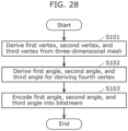
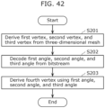
- a first angle, a second angle, and a third angle for deriving a fourth vertex of a second triangle which is formed on a second plane of the three-dimensional mesh using edges in common with the first triangle are derived (S102).
- a traversal symbol indicating any of skip, end, and execute may be encoded.
- a processing mode indicating any of coordinates, angles, a parallelogram, and a polygon may be encoded separately from the traversal symbol. Note that when a processing mode has been determined in advance, the processing mode need not be encoded and processing steps need not be switched.
- information for identifying fourth vertex D may include, as the dihedral angle information described above or in place of the dihedral angle information described above, "(3) information indicating a distance between a position of a vertex (fifth vertex E) of a polygon (corresponding triangle BEC) and a position of a processing object vertex (fourth vertex D) and a direction".
- information for identifying fourth vertex D may include, as the dihedral angle information described above or in place of the dihedral angle information described above, "(4) information indicating a difference between a plane including a polygon (corresponding triangle BEC) and a plane including a polygon (second triangle BDC) including a processing object vertex (fourth vertex D)".
- any of the pieces of information described above may be indicated using an angle. Accordingly, there is a possibility that a code amount may be reduced and flexibility and accuracy of prediction may improve. Furthermore, information indicating which of the pieces of information described above is to be used may be encoded.
- “(2) information related to a position and a shape of a polygon” may be information that identifies a position and a shape of corresponding triangle BEC.
- the information identifying the position and the shape of corresponding triangle BEC may indicate information indicating edge BC, an angle formed between edge BC and edge CE, and an angle formed between edge BC and edge BE.
- the information indicating edge BC corresponds to information indicating that corresponding triangle BEC is to be used.
- Information indicating one angle and a length of one edge may be encoded instead of the two angles described above.
- an angle formed between edge BC and edge BE and a length of edge BE may be encoded.
- information indicating one angle and a length of one perpendicular may be encoded instead of the two angles described above.
- an angle formed between edge BC and edge BE and a length of a perpendicular drawn from fifth vertex E to edge BC may be encoded.
- information indicating lengths of two edges may be encoded instead of the two angles described above.
- lengths of edge BE and edge CE may be encoded.
- (4) information indicating a difference between a plane including a polygon and a plane including a polygon including a processing object vertex may indicate an angle formed between a plane including corresponding triangle BEC and a plane including second triangle BDC.
- the angle for example, an angle formed between edge BE and edge BD or an angle formed between edge CE and edge CD may be encoded.
- the angle formed between edge BE and edge BD or the angle formed between edge CE and edge CD the angle itself may be encoded or an index that identifies one angle among a plurality of angles defined in advance may be encoded.
- the plurality of angles defined in advance may be commonly used when deriving the angle formed between edge BC and edge CE and the angle formed between edge BC and edge BE.
- an index indicating a plurality of combinations of the angle formed between edge BE and edge BD, the angle formed between edge CE and edge CD, the angle formed between edge BC and edge CE, and the angle formed between edge BC and edge BE may be defined in advance. Accordingly, a code amount can be further reduced as compared to a case where an angle itself is encoded.
- the angle may be omitted when the position of fourth vertex D coincides with the position of fifth vertex E or fourth vertex D is positioned on the same plane as fifth vertex E.
- a difference vector may be encoded in addition to an angle when the angle is expressed by an index, when the angle is expressed by integral accuracy, when a coordinate value is expressed by integral accuracy, and the like. Accordingly, the coordinate value of derived fourth vertex D can be corrected and accuracy of encoding can be improved.
- fourth vertex D may be used as first vertex A, second vertex B, or third vertex C with respect to other vertexes.
- processing methods may be switched among a plurality of processing methods.
- information indicating the processing method used to encode the processing object vertex may be encoded.
- processing methods may be switched among a plurality of processing methods by selecting a processing method in units of three-dimensional meshes and information indicating a processing method may be encoded in units of three-dimensional meshes.
- a processing method in accordance with a property of the three-dimensional mesh may become selectable and an improvement in subjective image quality and a reduction in a code amount may be possible.
- vertex as described in the present disclosure may mean a position of a vertex.
- the corresponding triangle in the above description may also be expressed as a predicted triangle or a virtual corresponding triangle.
- fifth vertex E of the corresponding triangle may also be expressed as a corresponding vertex, a corresponding point, a predicted vertex, or a predicted point.
- a second aspect of encoding and decoding of vertex information is an aspect that can be combined with the first aspect of encoding and decoding of vertex information.
- an imperfection of an input three-dimensional mesh causes an exception that requires a special handling tool.
- the exception can exist in various components of a polygon mesh, such as connectivity, a geometry coordinate, or a property attribute.
- Common defects in a 3D model are a degenerated face, overlapping vertexes, and a disconnected part.
- the overlapping vertexes have exactly the same coordinates but are expressed by two or more different indices. Therefore, the same point is expressed by different indices on different faces. Therefore, in traversing a topology of a mesh, these vertexes are not regarded as being the same, which leads to a failure of the encoding technique that depends on using a previously encoded vertex.
- the polygon mesh may include a disconnected part, that is an imperfect part, so that it may be difficult to traverse the entire model.
- a first condition is that the first vertex, the second vertex, and the third vertex are connected to each other.
- a second condition is that the first vertex, the second vertex, and the third vertex have already been encoded. Note that not only facility information but also vertex information may be derived and used for these determinations.
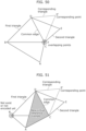
- FIG. 50 is a conceptual diagram illustrating an example of a mesh with overlapping vertexes, in which vertexes of a reference triangle are not decoded before decoding of a current vertex to be decoded.
- Vertexes C and F are two different points in the mesh and exist on different faces in the mesh. Vertexes C and F have the same coordinates and therefore are displayed as overlapping points.
- the fifth vertex is different from the first vertex, the second vertex, and the third vertex.
- the fifth vertex in the present aspect is a vertex used as an alternative to any of the first vertex, the second vertex, and the third vertex, and has a different meaning than the fifth vertex in the first aspect.
- FIG. 51 is a conceptual diagram illustrating an example of exception processing using a set of vertexes previously decoded. This example is an example in the case where vertex B does not satisfy the condition (vertex B does not exist or has not been decoded yet).
- the reference triangle formed by B, C, and D cannot be used for decoding of vertex E.
- Vertex B is replaced with previously decoded vertex A (fifth vertex), and a new virtual reference triangle ACD that can be used for decoding of vertex E is formed.
- the fifth vertex may be created as a dummy vertex having predefined coordinates.
- the virtual reference triangle may be formed by including the dummy vertex.
- Decoding device 200 may calculate the dummy vertex, as with encoding device 100.
- dummy vertexes may be previously defined at fixed coordinates (1, 0, 0), (0, 1, 0), and (0, 0, 1), and these dummy vertexes may serve as the first vertex, the second vertex, and the third vertex.
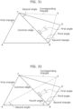
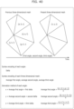
- the fourth vertex is derived using the plurality of angles (S226).
- the fourth vertex forms the second triangle together with an edge shared with the triangle formed by the derived three vertexes.
- FIGS. 31, 32 , and 33 illustrate different examples in which the fourth vertex is derived using derived three vertexes A, B, and C and the plurality of angles.
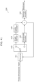
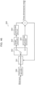
- FIG. 56 is a block diagram illustrating a configuration example of decoding device 200 according to the present aspect.
- Decoding device 200 decodes a three-dimensional mesh from a bitstream.
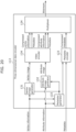
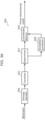
- decoding device 200 may include entropy decoder 266, traverser 261, determiner 267, exception processor 268, and coordinate deriver 264.
- Entropy decoder 266 acquires a bitstream. In addition, entropy decoder 266 decodes the connection information of the first vertex, the second vertex, and the third vertex and the plurality of angles from the bitstream. Here, the first vertex, the second vertex, and the third vertex form a first triangle.
- Determiner 267 checks whether the connection information satisfies a condition. When it is determined that the connection information satisfies the condition, coordinate deriver 264 performs processing using the first vertex, the second vertex, and the third vertex.
- Coordinate deriver 264 derives the fourth vertex in the three-dimensional mesh using the three vertexes and the plurality of angles and outputs the fourth vertex.
- the fourth vertex forms the second triangle together with an edge shared with the triangle formed by the three vertexes.
- whether to perform exception processing is determined based on the result of the determination of whether the information of the reference triangle satisfies a condition.
- the condition include the following conditions.
- conditions (i) and (ii) described above are examples, only one of the conditions may be used for determination, a different condition may be added, or at least one of the conditions may be replaced with another condition.
- information of the reference triangle may be used as a condition for the selection or switching.
- the reference triangle can be defined as a triangle that shares a vertex or an edge with a triangle having a current vertex to be processed.
- the triangle different from the reference triangle may be a triangle that does not share at least one of a vertex and an edge with a triangle having a current vertex to be processed. Note that both triangles may be a polygon other than the triangle.
- any or any combination of position information and connection information of a vertex of the reference triangle and information of whether or not a vertex can be used can be used (whether or not a vertex exists or whether or not a vertex has already been encoded or decoded) can be used.
- information of another triangle or information of a vertex of a triangle having a current vertex to be processed can also be used.
- processing may be selected from among or switched among a plurality of processing including the first processing and the second processing. That is, the plurality of processing may include different processing than the first processing and the second processing.
- the first processing may be processing performed using the reference triangle, and the second processing may be other processing performed using the reference triangle.
- the first processing may be processing performed using a triangle different from the reference triangle, and the second processing may be other processing performed using a triangle different from the reference triangle.
- the first processing may be processing performed using the reference triangle
- the second processing may be processing performed using another triangle at least one edge of which has no connectivity.
- processing performed using a further triangle each edge of which has connectivity may be defined. Then, processing may be selected from among or switched among a plurality of processing including the first processing, the second processing, and the third processing.
- selectable exception processing may vary with the determination result for a condition.
- Examples of the combination of the determination result for a condition and the exception processing include the following combinations.
- processing may be selected from among a plurality of processing including the first processing and the third processing.
- the increase of the processing amount may be able to be reduced, since the reference triangle is used regardless of the presence or absence of connectivity.
- a triangle that forms the same object as the object formed by a triangle having the current vertex to be processed may be used, so that the current vertex to be processed may be able to be more efficiently indicated than when performing the first processing.
- the processing when a vertex of the reference triangle has not been processed (encoded or decoded) yet, the processing may be selected from among a plurality of processing including the second processing and the third processing. In other words, the processing may be performed using a triangle different from the reference triangle, regardless of connectivity. The third processing may be more efficiently performed than the second processing.
- the third processing described above may be always selected.
- the reference triangle is set to be unavailable, and the processing may be performed using another triangle each vertex of which has been processed and each edge of which has connectivity. This arrangement may allow the processing to be more efficiently performed.
- position information of a vertex in the present disclosure is not limited to geometry coordinate information and may be other position information than geometry.
- a vertex that cannot be used for encoding or decoding is replaced with a vertex that has been already been encoded or decoded.
- Examples of the vertex that has already been encoded or decoded include the last three vertexes of a part that has been encoded or decoded in the mesh.
- One or more additional vertexes may be used for forming a new reference triangle.
- An index that indicates which vertexes are to be used for forming the reference triangle may be signaled from encoding device 100 to decoding device 200. Such signaling may be used not only in the case of an exception but also in the case of no exception. Furthermore, such signaling may be used not only in the "angle" prediction mode but also in other prediction modes that uses a reference triangle, such as a parallelogram prediction mode.
- a dummy reference triangle is generated using predefined vertexes.
- the predefined vertexes may be (1, 0, 0), (0, 1, 0), and (0, 0, 1).
- a new reference triangle may be created using the predefined vertexes.
- the new reference triangle may be used for processing of a vertex.
- FIG. 57 is a flowchart illustrating an example of the exception processing according to the present aspect.
- vertexes of a reference triangle are set by using predefined values (S301).
- S301 predefined values
- a vertex of a new triangle is then encoded or decoded using the reference triangle.
- FIG. 58 is a flowchart illustrating another example of the encoding processing according to the present aspect.
- encoding device 100 derives coordinates of a fourth vertex to be encoded from a mesh (S151).
- the triangle having the fourth vertex is defined as a second triangle
- a triangle that shares an edge with the second triangle is defined as a reference triangle.
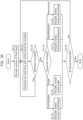
- Encoding device 100 derives connection information of the reference triangle from the mesh (S152). In the subsequent steps, encoding device 100 determines whether or not the connection information of the reference triangle satisfies a condition, and performs encoding processing of vertex coordinates based on the determination result.
- connection information of the reference triangle satisfies a condition
- encoding device 100 determines whether or not the connection information of the reference triangle satisfies a condition, and performs encoding processing of vertex coordinates based on the determination result.
- the following two determination processing will be shown, for example.
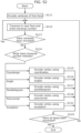
- encoding device 100 encodes information for determining the coordinates of the fourth vertex according to the exception processing illustrated in the present disclosure (S155, S156).
- encoding device 100 encodes information for determining the coordinates of the fourth vertex based on the reference triangle.
- angle information is used for encoding is shown (S156).
- the exception processing in the case where the condition (i) is not satisfied and the exception processing in the case where the condition (ii) is not satisfied may be different processing. Furthermore, not only the connection information but also vertex information may be derived and used for the determinations.
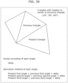
- FIG. 59 is a flowchart illustrating another example of the decoding processing according to the present aspect.
- decoding device 200 acquires, from a bitstream, information for determining the coordinates of a fourth vertex to be decoded.
- decoding of angle information is shown as an example (S251).
- the triangle having the fourth vertex is defined as a second triangle
- a triangle that shares an edge with the second triangle is defined as a reference triangle.
- Decoding device 200 derives connection information of the reference triangle from the bitstream (S252). In the subsequent steps, decoding device 200 determines whether or not the connection information of the reference triangle satisfies a condition, and performs decoding processing of vertex coordinates based on the determination result.
- the following two determination processing will be shown, for example.
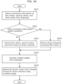
- decoding device 200 derives (decodes) the coordinates of the fourth vertex according to the exception processing illustrated in the present disclosure (S255, S256).
- decoding device 200 derives (decodes) the coordinates of the fourth vertex based on the reference triangle.
- S256 an example in which angle information is used for derivation (decoding) is shown.
- the exception processing in the case where the condition (i) is not satisfied and the exception processing in the case where the condition (ii) is not satisfied may be different processing. Furthermore, not only the connection information but also vertex information may be derived and used for the determinations.
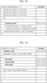
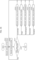
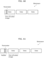
- FIG. 60 is a conceptual diagram illustrating an example of the position of a parameter in a bitstream. As illustrated in FIG. 60 , information for the exception processing may be signaled as a parameter in a bitstream.
- FIG. 61 is a conceptual diagram illustrating another example of the position of a parameter in a bitstream. As illustrated in FIG. 61 , information for the exception processing may be signaled as a parameter in a header of a bitstream.
- a parameter may be used to indicate the method of exception processing.
- the parameter is an index having a value of 0 or 1. The value can indicate whether a predefined dummy vertex is used or a signaled dummy vertex is used. When using a signaled dummy vertex, the dummy vertex is also signaled after the parameter.
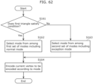
- FIG. 62 is a flowchart illustrating an example of basic encoding processing according to the present embodiment.
- circuit 151 of encoding device 100 illustrated in FIG. 24 performs the encoding processing illustrated in FIG. 62 .
- circuit 151 selects a mode for encoding a current vertex to be encoded of a second triangle from among a first set of modes including a normal mode that uses the first triangle to encode the current vertex (S162).
- circuit 151 selects the mode from among a second set of modes including an exception mode that uses a third triangle different from the first triangle and the second triangle to encode the current vertex to be encoded (S163).
- Circuit 151 then encodes the current vertex to be encoded according to the mode (S164).
- the first triangle when the first triangle does not satisfy the condition, it may be possible to use the third triangle different from the first triangle to encode the vertexes of the second triangle. Therefore, it may be possible to encode the vertexes of the second triangle by using a reference triangle suitable for the encoding.
- the third triangle may be a triangle that shares an edge with the first triangle.
- the third triangle may be a triangle that shares an edge with the second triangle.
- the third triangle may be a triangle that shares a vertex with the first triangle.
- the third triangle may be a triangle each vertex of which has been encoded.
- the third triangle may be a triangle each edge of which has connectivity.
- the third triangle may be a triangle that has a dummy vertex.
- the exception mode may include a plurality of sub-modes.
- circuit 151 may selects a sub-mode for encoding the current vertex from among the plurality of sub-modes.
- circuit 151 may encode a parameter indicating a sub-mode.
- encoding device 100 and decoding device 200 may share information of the sub-mode for encoding the current vertex to be encoded according to the parameter. Therefore, it may be possible to apply the same sub-mode to the encoding and the decoding according to the parameter.
- circuit 151 may determine a third triangle according to a sub-mode. In this case, selecting a sub-mode from among a plurality of sub-modes may make it possible to select a third triangle suitable for encoding. Therefore, it may be possible to efficiently encode the current vertex to be encoded by using a third triangle suitable for the encoding.
- circuit 151 may determine a vertex of a third triangle according to a sub-mode.
- selecting a sub-mode from among a plurality of sub-modes may make it possible to select vertexes of a third triangle suitable for encoding. Therefore, it may be possible to efficiently encode the current vertex to be encoded by using a third triangle suitable for the encoding.
- the condition may include that each vertex of the first triangle has been encoded.
- it may be possible to prevent a first triangle having a vertex that has not been encoded from being used for encoding the vertexes of the second triangle.
- it may be possible to use a mode suitable for the encoding of the vertexes of the second triangle.
- the condition may include that each edge of the first triangle has connectivity.
- circuit 151 may encode an angle indicating the current vertex using the third triangle.
- first triangle and the second triangle may share an edge.
- the edge shared by the first triangle and the second triangle may correspond to the opposite edge to the current vertex to be encoded of the second triangle.
- the third triangle may have edges shared with the first triangle and the second triangle. That is, the first triangle, the second triangle, and the third triangle may share edges. In this case, the third triangle shares an edge with the first triangle, shares an edge with the second triangle, shares vertexes with the first triangle, and shares vertexes with the second triangle.
- the third triangle is not limited to such a triangle, and may have any edge or any vertex of the first triangle, for example.
- the normal mode may be a mode for encoding the current vertex to be encoded using the first triangle and one or more angles.
- the exception mode may be a mode for encoding the current vertex to be encoded using the third triangle and one or more angles.
- the first set of modes and the second set of modes are different.
- the normal mode need not be included in the second set of modes and may be included only in the first set of modes.
- the exception mode need not be included in the first set of modes and may be included only in the second set of modes.
- the first set of modes may include at least one of a mode for encoding the current vertex to be encoded using coordinates, a mode for encoding the current vertex to be encoded using a parallelogram, and a mode for encoding the current vertex to be encoded using a polynomial.
- the parallelogram may be based on the first triangle.
- the normal mode may be a mode for encoding the current vertex to be encoded using a parallelogram based on the first triangle.
- the second set of modes may include at least one of a mode for encoding the current vertex to be encoded using coordinates, a mode for encoding the current vertex to be encoded using a parallelogram, and a mode for encoding the current vertex to be encoded using a polynomial.
- the parallelogram may be based on the third triangle.
- the exception mode may be a mode for encoding the current vertex to be encoded using a parallelogram based on the third triangle.
- the first set of modes may include only the normal mode. Furthermore, when the first triangle satisfies the condition, circuit 151 may select the normal mode. That is, when the first triangle satisfies the condition, circuit 151 may encode the current vertex to be encoded according to the normal mode.
- the second set of modes may include only the exception mode. Furthermore, when the first triangle does not satisfy the condition, circuit 151 may select the exception mode. That is, when the first triangle does not satisfy the condition, circuit 151 may encode the current vertex to be encoded according to the exception mode.
- circuit 151 may select the mode for encoding the current vertex to be encoded from among a set of modes including the normal mode and the exception mode.
- the set of modes can correspond to both the first set of modes and the second set of modes.
- circuit 151 may select the normal mode and encode the current vertex to be encoded according to the normal mode.
- circuit 151 may select the exception mode and encode the current vertex to be encoded according to the exception mode.
- the plurality of sub-modes may include a sub-mode for encoding the current vertex to be encoded using a third triangle having a dummy vertex.
- the plurality of sub-modes may include a sub-mode for encoding the current vertex to be encoded using a third triangle each vertex of which has been encoded.
- the plurality of sub-modes may include a sub-mode for encoding the current vertex to be encoded using a third triangle each edge of which has connectivity.
- the sub-mode may correspond to a condition concerning the third triangle or correspond to a condition concerning the vertexes of the third triangle.
- the sub-mode may correspond to the selection method for the third triangle or the vertexes of the third triangle.
- the normal mode may include a plurality of sub-modes.
- circuit 151 may select a sub-mode for encoding the current vertex to be encoded from among the plurality of sub-modes.
- Circuit 151 may determine the first triangle or the vertexes of the first triangle according to the sub-mode. That is, the sub-mode may correspond to the selection method for the first triangle or the vertexes of the first triangle.
- the sub-mode included in the exception mode may be expressed as an exception sub-mode.
- the sub-mode included in the normal mode may be expressed as a normal sub-mode.
- the mode may be expressed as processing.
- the normal mode, the exception mode, and the sub-mode may be expressed as normal processing, exception processing, and sub-processing, respectively.
- circuit 151 may encode the current vertex to be encoded by entropy encoding. Specifically, circuit 151 may encode an angle indicating the current vertex to be encoded by entropy encoding. Furthermore, for example, circuit 151 may encode one, two, or three angles for determining the current vertex to be encoded.
- the first triangle may be a reference triangle that is determined as a triangle close to the current vertex to be encoded according to a reference rule.
- each vertex described above may be expressed by geometry coordinates in the three-dimensional mesh.
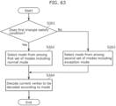
- FIG. 63 is a flowchart illustrating an example of basic decoding processing according to the present embodiment.
- circuit 251 of decoding device 200 illustrated in FIG. 25 performs the decoding processing illustrated in FIG. 63 .
- circuit 251 selects a mode for decoding a current vertex to be decoded of a second triangle from among a first set of modes including a normal mode that uses the first triangle to decode the current vertex (S262).
- circuit 251 selects the mode from among a second set of modes including an exception mode that uses a third triangle different from the first triangle and the second triangle to decode the current vertex to be decoded (S263).
- Circuit 251 decodes the current vertex to be decoded according to the mode (S264).
- the first triangle when the first triangle does not satisfy the condition, it may be possible to use the third triangle different from the first triangle to decode the vertexes of the second triangle. Therefore, it may be possible to decode the vertexes of the second triangle by using a reference triangle suitable for the decoding.
- the third triangle may be a triangle that shares an edge with the first triangle.
- the third triangle may be a triangle that shares an edge with the second triangle.
- the third triangle may be a triangle that shares a vertex with the first triangle.
- the third triangle may be a triangle each vertex of which has been decoded.
- the third triangle may be a triangle each edge of which has connectivity.
- the third triangle may be a triangle that has a dummy vertex.
- the exception mode may include a plurality of sub-modes.
- circuit 251 may selects a sub-mode for decoding the current vertex from among the plurality of sub-modes.
- circuit 251 may decode a parameter indicating a sub-mode.
- encoding device 100 and decoding device 200 may share information of the sub-mode for decoding the current vertex to be decoded according to the parameter. Therefore, it may be possible to apply the same sub-mode to the encoding and the decoding according to the parameter.
- circuit 251 may determine a third triangle according to a sub-mode.
- selecting a sub-mode from among a plurality of sub-modes may make it possible to select a third triangle suitable for decoding. Therefore, it may be possible to efficiently decode the current vertex to be decoded by using a third triangle suitable for the decoding.
- circuit 251 may determine a vertex of a third triangle according to a sub-mode.
- selecting a sub-mode from among a plurality of sub-modes may make it possible to select vertexes of a third triangle suitable for decoding. Therefore, it may be possible to efficiently decode the current vertex to be decoded by using a third triangle suitable for the decoding.
- the condition may include that each vertex of the first triangle has been decoded.
- it may be possible to prevent a first triangle having a vertex that has not been decoded from being used for decoding the vertexes of the second triangle.
- it may be possible to use a mode suitable for the decoding of the vertexes of the second triangle.
- the condition may include that each edge of the first triangle has connectivity.
- circuit 251 may decode an angle indicating the current vertex using the third triangle. In this case, it may be possible to prevent the code amount from being excessively high. That is, it may be possible to reduce the worst-case code amount.
- first triangle and the second triangle may share an edge.
- the edge shared by the first triangle and the second triangle may correspond to the opposite edge to the current vertex to be decoded of the second triangle.
- the third triangle may have edges shared with the first triangle and the second triangle. That is, the first triangle, the second triangle, and the third triangle may share edges. In this case, the third triangle shares an edge with the first triangle, shares an edge with the second triangle, shares vertexes with the first triangle, and shares vertexes with the second triangle.
- the third triangle is not limited to such a triangle, and may have any edge or any vertex of the first triangle, for example.
- the normal mode may be a mode for decoding the current vertex to be decoded using the first triangle and one or more angles.
- the exception mode may be a mode for decoding the current vertex to be decoded using the third triangle and one or more angles.
- the first set of modes and the second set of modes are different.
- the normal mode need not be included in the second set of modes and may be included only in the first set of modes.
- the exception mode need not be included in the first set of modes and may be included only in the second set of modes.
- the first set of modes may include at least one of a mode for decoding the current vertex to be decoded using coordinates, a mode for decoding the current vertex to be decoded using a parallelogram, and a mode for decoding the current vertex to be decoded using a polynomial.
- the parallelogram may be based on the first triangle.
- the normal mode may be a mode for decoding the current vertex to be decoded using a parallelogram based on the first triangle.
- the second set of modes may include at least one of a mode for decoding the current vertex to be decoded using coordinates, a mode for decoding the current vertex to be decoded using a parallelogram, and a mode for decoding the current vertex to be decoded using a polynomial.
- the parallelogram may be based on the third triangle.
- the exception mode may be a mode for decoding the current vertex to be decoded using a parallelogram based on the third triangle.
- the first set of modes may include only the normal mode. Furthermore, when the first triangle satisfies the condition, circuit 251 may select the normal mode. That is, when the first triangle satisfies the condition, circuit 251 may decode the current vertex to be decoded according to the normal mode.
- the second set of modes may include only the exception mode. Furthermore, when the first triangle does not satisfy the condition, circuit 251 may select the exception mode. That is, when the first triangle does not satisfy the condition, circuit 251 may decode the current vertex to be decoded according to the exception mode.
- circuit 251 may select the mode for decoding the current vertex to be decoded from among a set of modes including the normal mode and the exception mode.
- the set of modes can correspond to both the first set of modes and the second set of modes.
- circuit 251 may select the normal mode and decode the current vertex to be decoded according to the normal mode.
- circuit 251 may select the exception mode and decode the current vertex to be decoded according to the exception mode.
- the plurality of sub-modes may include a sub-mode for decoding the current vertex to be decoded using a third triangle having a dummy vertex.
- the plurality of sub-modes may include a sub-mode for decoding the current vertex to be decoded using a third triangle each vertex of which has been decoded.
- the plurality of sub-modes may include a sub-mode for decoding the current vertex to be decoded using a third triangle each edge of which has connectivity.
- the sub-mode may correspond to a condition concerning the third triangle or correspond to a condition concerning the vertexes of the third triangle.
- the sub-mode may correspond to the selection method for the third triangle or the vertexes of the third triangle.
- the normal mode may include a plurality of sub-modes.
- circuit 251 may select a sub-mode for decoding the current vertex to be decoded from among the plurality of sub-modes.
- Circuit 251 may determine the first triangle or the vertexes of the first triangle according to the sub-mode. That is, the sub-mode may correspond to the selection method for the first triangle or the vertexes of the first triangle.
- the sub-mode included in the exception mode may be expressed as an exception sub-mode.
- the sub-mode included in the normal mode may be expressed as a normal sub-mode.
- the mode may be expressed as processing.
- the normal mode, the exception mode, and the sub-mode may be expressed as normal processing, exception processing, and sub-processing, respectively.
- circuit 251 may decode the current vertex to be decoded by entropy decoding. Specifically, circuit 251 may decode an angle indicating the current vertex to be decoded by entropy decoding. Furthermore, for example, circuit 251 may decode one, two, or three angles for determining the current vertex to be decoded.
- the first triangle may be a reference triangle that is determined as a triangle close to the current vertex to be decoded according to a reference rule.
- each vertex described above may be expressed by geometry coordinates in the three-dimensional mesh.
- Selector 171 is an electric circuit, for example. Selector 171 may correspond to traverser 161, determiner 167, exception processor 168, and the like described above, or may be implemented by circuit 151 and memory 152 described above.
- selector 171 selects a mode from among a first set of modes including a normal mode when a first triangle satisfies a condition, and selects a mode from among a second set of modes including an exception mode when the first triangle does not satisfy the condition.
- Encoding processor 172 then encodes the current vertex to be encoded according to the mode.
- the first triangle when the first triangle does not satisfy the condition, it may be possible to use a third triangle different from the first triangle to encode the vertexes of a second triangle. Therefore, it may be possible to encode the vertexes of the second triangle by using a reference triangle suitable for the encoding.
- FIG. 65 is a block diagram illustrating another configuration example of decoding device 200 according to the present embodiment.
- decoding device 200 includes selector 271 and decoding processor 272.
- Selector 271 is an electric circuit, for example. Selector 271 may correspond to traverser 261, determiner 267, exception processor 268, and the like described above, or may be implemented by circuit 251 and memory 252 described above.
- Decoding processor 272 is an electric circuit, for example. Decoding processor 272 may correspond to coordinate deriver 264, entropy decoder 266, and the like described above, or may be implemented by circuit 251 and memory 252 described above.
- selector 271 selects a mode from among a first set of modes including a normal mode when a first triangle satisfies a condition, and selects a mode from among a second set of modes including an exception mode when the first triangle does not satisfy the condition.
- Decoding processor 272 then decodes the current vertex to be decoded according to the mode.
- the first triangle when the first triangle does not satisfy the condition, it may be possible to use a third triangle different from the first triangle to decode the vertexes of a second triangle. Therefore, it may be possible to decode the vertexes of the second triangle by using a reference triangle suitable for the decoding.
- encoding device 100 and decoding device 200 have thus far been described according to the embodiment, the aspects of encoding device 100 and decoding device 200 are not limited to the embodiment. Modifications that may be conceived by a person skilled in the art may be applied to the embodiment, and a plurality of constituent elements in the embodiment may be combined in any manner.
- processing performed by a specific constituent element in the embodiment may be performed by a different constituent element instead of the specific constituent element.
- the order of processes may be changed or processes may be performed in parallel.
- the encoding and the decoding in the present disclosure may be applied to encoding and decoding of vertex information indicating a position of a vertex. It should be noted that the application of the encoding and the decoding in the present disclosure is not limited to a vertex of a face in a three-dimensional mesh, and the encoding and the decoding in the present disclosure may be applied to encoding and decoding of vertex information indicating a different vertex. In addition, each of the processes in the present disclosure may be performed as one of selectable processes.
- At least part of the processes in the present disclosure may be used as an encoding method or a decoding method.
- a program for causing a computer to execute the encoding method or the decoding method may be used.
- a non-transitory computer-readable recording medium on which the program is recorded may be used.
- a bitstream for causing decoding device 200 to perform decoding may be used.
- At least part of the plurality of constituent elements and the processes in the present disclosure may be used as a transmitting device, a receiving device, a transmitting method, and a receiving method.
- a program for causing a computer to execute the transmitting method or the receiving method may be used.
- a non-transitory computer-readable recording medium on which the program is recorded may be used.
- the present disclosure is useful in, for example, an encoding device, a decoding device, a transmitting device, a receiving device, and the like related to a three-dimensional mesh and can be applied to a computer graphics system, a three-dimensional data display system, and the like.
Landscapes
- Engineering & Computer Science (AREA)
- Multimedia (AREA)
- Physics & Mathematics (AREA)
- General Physics & Mathematics (AREA)
- Theoretical Computer Science (AREA)
- Compression Or Coding Systems Of Tv Signals (AREA)
Applications Claiming Priority (3)
| Application Number | Priority Date | Filing Date | Title |
|---|---|---|---|
| US202263349243P | 2022-06-06 | 2022-06-06 | |
| US202363465033P | 2023-05-09 | 2023-05-09 | |
| PCT/JP2023/021028 WO2023238867A1 (ja) | 2022-06-06 | 2023-06-06 | 符号化装置、復号装置、符号化方法及び復号方法 |
Publications (2)
| Publication Number | Publication Date |
|---|---|
| EP4538977A1 true EP4538977A1 (de) | 2025-04-16 |
| EP4538977A4 EP4538977A4 (de) | 2025-10-08 |
Family
ID=89118370
Family Applications (1)
| Application Number | Title | Priority Date | Filing Date |
|---|---|---|---|
| EP23819847.7A Pending EP4538977A4 (de) | 2022-06-06 | 2023-06-06 | Codierungsvorrichtung, decodierungsvorrichtung, codierungsverfahren und decodierungsverfahren |
Country Status (7)
| Country | Link |
|---|---|
| US (1) | US20250095214A1 (de) |
| EP (1) | EP4538977A4 (de) |
| JP (2) | JP7723199B2 (de) |
| KR (1) | KR20250019630A (de) |
| CN (1) | CN119301642A (de) |
| MX (1) | MX2024014355A (de) |
| WO (1) | WO2023238867A1 (de) |
Families Citing this family (4)
| Publication number | Priority date | Publication date | Assignee | Title |
|---|---|---|---|---|
| WO2025148072A1 (zh) * | 2024-01-12 | 2025-07-17 | Oppo广东移动通信有限公司 | 编解码方法、码流、编码器、解码器以及存储介质 |
| WO2025182831A1 (ja) * | 2024-02-28 | 2025-09-04 | パナソニック インテレクチュアル プロパティ コーポレーション オブ アメリカ | 符号化方法、復号方法、符号化装置及び復号装置 |
| US20260087740A1 (en) * | 2024-09-24 | 2026-03-26 | Roblox Corporation | Merging coplanar convex polygons in constructive solid geometry (csg) |
| CN121120809B (zh) * | 2025-11-12 | 2026-02-10 | 摩尔线程智能科技(北京)股份有限公司 | 图元编码方法、装置、设备、存储介质及程序产品 |
Family Cites Families (7)
| Publication number | Priority date | Publication date | Assignee | Title |
|---|---|---|---|---|
| US6668091B1 (en) * | 1998-10-02 | 2003-12-23 | Samsung Electronics Co., Ltd. | 3D mesh coding/decoding method |
| US6577310B1 (en) * | 1998-12-01 | 2003-06-10 | Samsung Electronics Co., Ltd. | 3D mesh coding/decoding method and apparatus for error resilience and incremental rendering |
| US8830235B1 (en) * | 1999-09-13 | 2014-09-09 | Alcatel Lucent | Non-uniform relaxation procedure for multiresolution mesh processing |
| EP2216750A1 (de) * | 2009-02-06 | 2010-08-11 | Thomson Licensing | Verfahren und Vorrichtung zum Kodieren dreidimensionaler Maschenmodelle und Verfahren und Vorrichtung zum Dekodieren kodierter dreidimensionaler Maschenmodelle |
| GB2561824B (en) * | 2017-04-19 | 2020-04-01 | Canon Kk | Encoding and decoding of geometry data in a 3D model based on evaluated regularity of the model |
| US10783669B2 (en) * | 2018-09-26 | 2020-09-22 | Google Llc | Texture coordinate compression using texture atlas |
| WO2023074673A1 (ja) * | 2021-10-26 | 2023-05-04 | パナソニック インテレクチュアル プロパティ コーポレーション オブ アメリカ | 符号化装置、復号装置、符号化方法及び復号方法 |
-
2023
- 2023-06-06 KR KR1020247038325A patent/KR20250019630A/ko active Pending
- 2023-06-06 JP JP2024526458A patent/JP7723199B2/ja active Active
- 2023-06-06 WO PCT/JP2023/021028 patent/WO2023238867A1/ja not_active Ceased
- 2023-06-06 EP EP23819847.7A patent/EP4538977A4/de active Pending
- 2023-06-06 CN CN202380043575.9A patent/CN119301642A/zh active Pending
-
2024
- 2024-11-20 MX MX2024014355A patent/MX2024014355A/es unknown
- 2024-12-02 US US18/965,181 patent/US20250095214A1/en active Pending
-
2025
- 2025-07-31 JP JP2025128166A patent/JP2025166019A/ja active Pending
Also Published As
| Publication number | Publication date |
|---|---|
| JP7723199B2 (ja) | 2025-08-13 |
| JPWO2023238867A1 (de) | 2023-12-14 |
| JP2025166019A (ja) | 2025-11-05 |
| MX2024014355A (es) | 2024-12-06 |
| KR20250019630A (ko) | 2025-02-10 |
| WO2023238867A1 (ja) | 2023-12-14 |
| EP4538977A4 (de) | 2025-10-08 |
| CN119301642A (zh) | 2025-01-10 |
| US20250095214A1 (en) | 2025-03-20 |
Similar Documents
| Publication | Publication Date | Title |
|---|---|---|
| EP4425435A1 (de) | Codierungsvorrichtung, decodierungsvorrichtung, codierungsverfahren und decodierungsverfahren | |
| EP4538977A1 (de) | Codierungsvorrichtung, decodierungsvorrichtung, codierungsverfahren und decodierungsverfahren | |
| US20250220233A1 (en) | Encoding device, decoding device, encoding method, and decoding method | |
| US20250322550A1 (en) | Encoding method, decoding method, encoding device, and decoding device | |
| EP4697270A1 (de) | Codierungsvorrichtung, decodierungsvorrichtung, codierungsverfahren und decodierungsverfahren | |
| US20260057559A1 (en) | Decoding method, encoding method, decoding device, and encoding device | |
| US20260004466A1 (en) | Encoding device, decoding device, encoding method, and decoding method | |
| US20250371743A1 (en) | Encoding method, decoding method, encoding device, and decoding device | |
| US20260120332A1 (en) | Encoding device, decoding device, encoding method, and decoding method | |
| US20260113480A1 (en) | Encoding method, decoding method, encoding device, and decoding device | |
| US20260120333A1 (en) | Encoding device, decoding device, encoding method, and decoding method | |
| CN118140250A (zh) | 编码装置、解码装置、编码方法及解码方法 | |
| WO2025070342A1 (ja) | 符号化装置、復号装置、符号化方法及び復号方法 | |
| WO2025150425A1 (ja) | 復号方法、符号化方法、復号装置及び符号化装置 | |
| WO2025220615A1 (ja) | 符号化方法、復号方法、符号化装置及び復号装置 | |
| WO2025216144A1 (ja) | 符号化方法、復号方法、符号化装置及び復号装置 | |
| WO2025220696A1 (ja) | 符号化方法、復号方法、符号化装置及び復号装置 | |
| WO2025220701A1 (ja) | 符号化方法、復号方法、符号化装置及び復号装置 | |
| WO2025074908A1 (ja) | 符号化装置、復号装置、符号化方法及び復号方法 | |
| WO2025216315A1 (ja) | 符号化方法、復号方法、符号化装置及び復号装置 | |
| WO2025154742A1 (ja) | 符号化方法、復号方法、符号化装置及び復号装置 | |
| WO2026009768A1 (ja) | 符号化方法、復号方法、符号化装置及び復号装置 | |
| WO2026084019A1 (ja) | 復号方法、符号化方法、復号装置及び符号化装置 | |
| WO2026094612A1 (ja) | 符号化方法、復号方法、符号化装置及び復号装置 | |
| WO2025220707A1 (ja) | 符号化方法、復号方法、符号化装置及び復号装置 |
Legal Events
| Date | Code | Title | Description |
|---|---|---|---|
| STAA | Information on the status of an ep patent application or granted ep patent |
Free format text: STATUS: THE INTERNATIONAL PUBLICATION HAS BEEN MADE |
|
| PUAI | Public reference made under article 153(3) epc to a published international application that has entered the european phase |
Free format text: ORIGINAL CODE: 0009012 |
|
| STAA | Information on the status of an ep patent application or granted ep patent |
Free format text: STATUS: REQUEST FOR EXAMINATION WAS MADE |
|
| 17P | Request for examination filed |
Effective date: 20241115 |
|
| AK | Designated contracting states |
Kind code of ref document: A1 Designated state(s): AL AT BE BG CH CY CZ DE DK EE ES FI FR GB GR HR HU IE IS IT LI LT LU LV MC ME MK MT NL NO PL PT RO RS SE SI SK SM TR |
|
| DAV | Request for validation of the european patent (deleted) | ||
| DAX | Request for extension of the european patent (deleted) | ||
| A4 | Supplementary search report drawn up and despatched |
Effective date: 20250908 |
|
| RIC1 | Information provided on ipc code assigned before grant |
Ipc: G06T 9/00 20060101AFI20250902BHEP |