EP4538982A1 - Computerimplementiertes verfahren zur analyse einer herzklappe, computerprogramm und system - Google Patents
Computerimplementiertes verfahren zur analyse einer herzklappe, computerprogramm und system Download PDFInfo
- Publication number
- EP4538982A1 EP4538982A1 EP23202665.8A EP23202665A EP4538982A1 EP 4538982 A1 EP4538982 A1 EP 4538982A1 EP 23202665 A EP23202665 A EP 23202665A EP 4538982 A1 EP4538982 A1 EP 4538982A1
- Authority
- EP
- European Patent Office
- Prior art keywords
- valve
- model
- heart valve
- data set
- topology
- Prior art date
- Legal status (The legal status is an assumption and is not a legal conclusion. Google has not performed a legal analysis and makes no representation as to the accuracy of the status listed.)
- Withdrawn
Links
Images


Classifications
-
- G—PHYSICS
- G06—COMPUTING OR CALCULATING; COUNTING
- G06T—IMAGE DATA PROCESSING OR GENERATION, IN GENERAL
- G06T19/00—Manipulating three-dimensional [3D] models or images for computer graphics
- G06T19/20—Editing of three-dimensional [3D] images, e.g. changing shapes or colours, aligning objects or positioning parts
-
- G—PHYSICS
- G06—COMPUTING OR CALCULATING; COUNTING
- G06T—IMAGE DATA PROCESSING OR GENERATION, IN GENERAL
- G06T7/00—Image analysis
- G06T7/0002—Inspection of images, e.g. flaw detection
- G06T7/0012—Biomedical image inspection
-
- G—PHYSICS
- G06—COMPUTING OR CALCULATING; COUNTING
- G06T—IMAGE DATA PROCESSING OR GENERATION, IN GENERAL
- G06T7/00—Image analysis
- G06T7/10—Segmentation; Edge detection
- G06T7/11—Region-based segmentation
-
- G—PHYSICS
- G16—INFORMATION AND COMMUNICATION TECHNOLOGY [ICT] SPECIALLY ADAPTED FOR SPECIFIC APPLICATION FIELDS
- G16H—HEALTHCARE INFORMATICS, i.e. INFORMATION AND COMMUNICATION TECHNOLOGY [ICT] SPECIALLY ADAPTED FOR THE HANDLING OR PROCESSING OF MEDICAL OR HEALTHCARE DATA
- G16H30/00—ICT specially adapted for the handling or processing of medical images
- G16H30/40—ICT specially adapted for the handling or processing of medical images for processing medical images, e.g. editing
-
- G—PHYSICS
- G06—COMPUTING OR CALCULATING; COUNTING
- G06T—IMAGE DATA PROCESSING OR GENERATION, IN GENERAL
- G06T2200/00—Indexing scheme for image data processing or generation, in general
- G06T2200/24—Indexing scheme for image data processing or generation, in general involving graphical user interfaces [GUIs]
-
- G—PHYSICS
- G06—COMPUTING OR CALCULATING; COUNTING
- G06T—IMAGE DATA PROCESSING OR GENERATION, IN GENERAL
- G06T2207/00—Indexing scheme for image analysis or image enhancement
- G06T2207/10—Image acquisition modality
- G06T2207/10132—Ultrasound image
- G06T2207/10136—3D ultrasound image
-
- G—PHYSICS
- G06—COMPUTING OR CALCULATING; COUNTING
- G06T—IMAGE DATA PROCESSING OR GENERATION, IN GENERAL
- G06T2207/00—Indexing scheme for image analysis or image enhancement
- G06T2207/30—Subject of image; Context of image processing
- G06T2207/30004—Biomedical image processing
- G06T2207/30048—Heart; Cardiac
-
- G—PHYSICS
- G06—COMPUTING OR CALCULATING; COUNTING
- G06T—IMAGE DATA PROCESSING OR GENERATION, IN GENERAL
- G06T2210/00—Indexing scheme for image generation or computer graphics
- G06T2210/41—Medical
-
- G—PHYSICS
- G06—COMPUTING OR CALCULATING; COUNTING
- G06T—IMAGE DATA PROCESSING OR GENERATION, IN GENERAL
- G06T2219/00—Indexing scheme for manipulating 3D models or images for computer graphics
- G06T2219/004—Annotating, labelling
-
- G—PHYSICS
- G06—COMPUTING OR CALCULATING; COUNTING
- G06T—IMAGE DATA PROCESSING OR GENERATION, IN GENERAL
- G06T2219/00—Indexing scheme for manipulating 3D models or images for computer graphics
- G06T2219/008—Cut plane or projection plane definition
-
- G—PHYSICS
- G06—COMPUTING OR CALCULATING; COUNTING
- G06T—IMAGE DATA PROCESSING OR GENERATION, IN GENERAL
- G06T2219/00—Indexing scheme for manipulating 3D models or images for computer graphics
- G06T2219/20—Indexing scheme for editing of 3D models
- G06T2219/2012—Colour editing, changing, or manipulating; Use of colour codes
Definitions
- Three-dimensional (3D) echocardiography is a common method to visualize the human heart and in particular the heart valves.
- 3D ultrasound images are acquired of the moving heart over a period of time, resulting in a video clip, also termed 3D echo clip, this is termed four-dimensional (4D) echocardiography.
- 4D echocardiography is commonly used to plan and perform minimally invasive heart surgery, such as trans-catheter valve procedures.
- valve repair through leaflet clipping is becoming a common method to reduce regurgitant blood flow and improve the patient's quality of life significantly.
- the interventional cardiologists need to know which leaflets they have to clip during the procedure. Therefore, a good planning tool is required, as well as a good method of visualising the heart valves during the interventional procedure.
- US 2005187461A discloses a computerized method of facilitating cardiac intervention, comprising inputting patient data, creating a computerized interactive model of a heart based on the patient data, simulating at least one proposed cardiac intervention treatment by adding or deleting features to the model, and determining the effects of the proposed cardiac simulation upon the entire model. Simulations may be repeated to allow the user to determine an optimal cardiac intervention. Additionally, a template may be created from the model to use as a guide during the cardiac intervention.
- the 3D or 4D volume data set may be or have been obtained by a medical imaging modality, preferably by ultrasound, for example by 3D or 4D echocardiography, in particular by transoesophageal 4D echocardiography.
- a medical imaging modality preferably by ultrasound
- 3D or 4D echocardiography in particular by transoesophageal 4D echocardiography.
- Other possible imaging modalities are magnetic resonance imaging (MRI), X-ray imaging, Positron Emission Spectroscopy (PET), or computed tomography (CT).
- MRI magnetic resonance imaging
- PET Positron Emission Spectroscopy
- CT computed tomography
- a 3D volume data set comprises a 3D matrix of voxels, each voxel comprising a greyscale value representing image information.
- the fourth dimension is time.
- the valve model is based on or is correlated to a topology-based 2D model of the heart valve.
- the topology-based 2D model may be derived from the 3D valve model.
- the topology-based 2D model is essentially a further simplification of the 3D valve model, in that the 2D model does not extend into the third dimension, in particular not in a dimension perpendicular to the main plane of the annulus.
- the topology-based 2D model may be derived by projecting or mapping the 3D valve model onto a plane. When mapping the 3D valve model onto a plane to obtain the topology-based 2D model, the proportions of the annulus of the 3D valve model may be preserved.
- the projection of the 3D valve model onto a 2D surface may be distorted to obtain the topology-based 2D model.
- the topology-based 2D model is created based on a developable surface of the segmented heart valve or the 3D valve model.
- a developable surface is a surface that can be flattened onto a plane without distortion, i.e., by "folding", "bending", etc.
- the topology-based 2D model may be the developable surface enclosed by the 3D ring of the 3D valve model, flattened onto a 2D plane.
- the thus obtained "flattened” 2D closed curve may be further simplified by transforming it to a standardised shape, such as a circle, or an ellipse.
- the valve model in particular the 3D valve model, is tracked over at least one heartbeat in a 4D volume data set.
- the valve model can be visualised in any of the frames, and preferably adapted by a user to best fit the segmented heart valve, or a 3D or 4D visualisation of the heart valve or the segmented heart valve.
- the mapping of the 3D valve model to the topology-based 2D model is also tracked over the heartbeats, so that the models can be visualised at any time point during the heart cycle.
- the topology-based 2D model is preferably static, in that it does not change over a heartbeat.
- the topology-based 2D model is preferably a standardised simplification of an actual segmentation of the heart valve.
- a 3D representation of the heart valve for example the segmented heart valve, is transferred to a 2D visualisation of the heart valve.
- Such standardised representation of a heart valve is highly useful, since it has been found that heart valves may differ considerably in their morphology, to an extent that even the number of leaflets may differ between patients, in particular some may have two leaflets, other may have three leaflets, and a standardised representation thereof may considerably help in diagnosis.
- the volume-of-interest therefore describes and comprises a 3D volume above and/or below the heart valve, in particular the region into which the valve leaflets may move during a heart cycle.
- the volume-of-interest includes at least one 3D region, which is defined as being the projection of a 2D section within the valve model.
- a 2D section may for example define an area corresponding to a leaflet or another morphological or physiological feature of the heart valve.
- the corresponding 3D region is the projection of such a 2D section along the projection direction.
- the volume-of-interest includes at least one sub-volume, termed 3D-region, which also has the shape of the cylinder, not a circular cylinder, wherein the base of this sub-cylinder is a section corresponding to a morphological or physical feature.
- such a 3D-region may have the shape of a slice of pie, the pie being the volume-of-interest.
- each leaflet may mainly move within its own 3D region within the volume-of-interest.
- each of the voxels in the at least one 3D region is labelled with label indicative of the morphological or physiological feature of the corresponding 2D section, for example a label indicating the particular heart valve.
- the valve model and in particular the projection direction is adapted to the position of the heart valve in each 3D frame of a 4D volume data set.
- the 3D valve model is adapted over time, and is fitted to the annulus as it moves over a heart cycle.
- the topology-based 2D model may be placed in the main plane of the annulus in each frame, for example as identified on the segmented heart valve.
- the projection direction is determined as described below.
- the method comprises a further step of (e) providing a visualisation of the 3D or 4D volume data set of the heart valve, the visualisation comprising information from the projected valve model, in particular wherein voxels having different labels are visualised differently.
- the visualisation may for example be a rendering of the 3D or 4D volume data set, in case of a 4D volume data set preferably a dynamic rendering over at least one heart cycle.
- the different 3D regions within the volume-of-interest are preferably visualised differently, so that the user may be always aware of the anatomical region he is navigating through, when viewing the visualisation.
- the voxels in the at least one 3D region of the volume-of-interest are represented in a colour depending on their label.
- at least two 3D regions of the volume-of-interest are represented in different colours.
- the 3D regions belonging to different leaflets may be coloured differently.
- This colour coding allows a user to be always aware of the leaflet region he/she is navigating through.
- the 3D-regions may be coloured in one of red, green, yellow, magenta, orange or blue, or any other colour. Since it is sometimes hard to determine where exactly the leaflets meet in the centre of the heart valve, it is possible to leave a central 3D region unlabelled.
- the visualisation includes visualising a 2D cut plane through the 3D or 4D volume data set.
- the 2D cut plane may be generated from the 3D or 4D volume data set by means of MPR.
- the 2D cut plane may be oriented in any user-selected orientation through the volume data set.
- the 3D regions of the volume-of-interest may be intersected at any angle.
- the user is aided in finding his/her orientation within the volume data set.
- all voxels in a 3D-region are coloured in the same colour, corresponding to the respective 2D section in the valve model.
- All 2D cut planes at any position and orientation through the volume data set, and preferably in any one of a sequence of frames, can display the corresponding colour, so that the location of a specific morphological or physiological feature of the heart valve is indicated.
- anatomical knowledge is transformed into a colour-coding, which allows the user to be always aware of the leaflet region which he/she is navigating through.
- One can thereby navigate through the structures in the image without having to switch between image information and model information.
- volume-of-interest may remain unshaded.
- structures outside of the volume-of-interest, or outside of the volume-of-interest plus a certain margin, may not be represented at all.
- the volume-of-interest may also be used to "cut free" the heart valve, in order for it to be even better visualised.
- the voxels which are outside of the volume-of-interest are not visualised in the visualisation. This is a useful embodiment, because orientation within the data set may be further facilitated by cutting away those regions which are not of interest in the analysis of the valves.
- Voxels "outside of the volume-of-interest" may either be understood in the literal sense, or it may mean outside of the volume-of-interest with a certain margin, for example a user-defined margin of for example 3-15 millimetres, so as to cover also the neighbouring regions of the valve.
- voxels outside of the volume-of-interest are visualised differently, for example in a neutral colour, or in a lighter shade than the voxels within the volume-of-interest.
- the centre of the valve model may include an inner circle as the central region, which may be concentric to the closed curve.
- the commissure points may describe a subtle structure that can be identified by two anatomical landmarks, for example the axis of corresponding papillary muscles and the commissure chordae which have a specific fan-like configuration.
- a 2D section of the at least one 2D section within the closed curve corresponds to a physiological feature, wherein preferably the physiological feature is a flow phenomenon.
- the topology-based 2D model may be used to also define physiological features of the heart valve in a standardised manner, in particular projected onto the 2D plane of the topology-based 2D model.
- certain areas where a blood flow phenomenon occurs may be represented as 2D sections on the topology-based 2D model.
- Such flow phenomena may for example be an area of regurgitant flow. If this is represented in a different way in a visualisation of the 3D or 4D volume data set, it may provide valuable information to the physician as to the exact position of the valve prolapse, thus assisting the planning of a surgery.
- the flow phenomenon may also be a blood flow from a neighbouring valve, which the user wants to exclude from the visualisation of blood flow in the 3D or 4D volume data set.
- a respective section can be defined automatically or by the user on the topology-based 2D model.
- the 3D region relating to this section of undesired flow measurements may be labelled as an area where no flow phenomena are to be visualised.
- the user may choose a visualisation of the 3D or 4D volume data set, in which flow information is included, in particular flow information from Doppler ultrasound measurements.
- the 3D region relating to the 2D section of undesired flow measurement may be excluded from the flow visualisation.
- the 3D valve model may first be projected into a plane, in particular a plane which is perpendicular to the projection direction.
- the 3D valve model is not necessarily limited to a 2D plane, but may have a three-dimensional shape. Therefore, one may calculate the orientation of a plane which has the least quadratic distance to a non-planar surface enclosed by the closed curve of the valve model. Therein, for example a set number of points, such as 5-30, preferably 10-20, points are distributed over the non-planar surface of the 3D model. Then, a minimisation algorithm is performed in order to find a plane which minimises the sum of the squares of the distances from each point to the plane.
- This plane is also referred to as "fitted plane” and may correspond to the main plane of the annulus.
- the fitted plane may be determined only from points on the outer circumference of the 3D valve model (the 3D ring), preferably also by minimising the sum of squares of the distances from the outer circumference to a corresponding flat ring.
- the flat ring then defines the plane.
- the 3D valve model may be projected into this plane, together with any 2D sections comprised therein, to result in a 2D valve model.
- This 2D valve model is then the valve model that is projected into the 3D or 4D volume data set.
- the orientation of the fitted plane is taken as the orientation of the topology-based 2D model
- the topology-based 2D model is the valve model that is projected into the 3D or 4D volume data set.
- the topology-based 2D model is then positioned at the position of the 3D valve model, thus it is positioned over the annulus of the heart valve.
- any commissure points defined on the topology-based 2D model are positioned as close as possible, for example calculated by a minimisation algorithm, to the commissure points as defined in the 3D or 4D volume data set, or on the 3D valve model or on the segmented heart valve.
- a projection direction which extends from the area of the heart valve into the heart can be identified, and the projection of the topology-based 2D model can be performed as accurately as possible.
- the volume-of-interest extends into the 3D or 4D volume data set up to a set height along the projection direction, preferably a height which is proportionate to a dimension of the valve model.
- the height of the volume-of-interest is not the complete height of the volume data set.
- a topology-based 2D model of the heart valve is used, which is preferably a highly simplified valve model represented on a plane, i.e., it is 2D-dimensional (2D) in the sense that all elements of the topology-based 2D model can be represented in 2D coordinates.
- the topology-based 2D model preferably comprises a closed curve representing the annulus.
- the closed curve preferably has a standardized shape, for example a circle, ellipse, polygon, or polygon with rounded edges.
- the size of the closed curve may be standardised, regardless of the actual size of the heart valve annulus. In other embodiments, the size of the closed curve is proportional to the actual size, e.g.
- a 3D visualisation of the 3D valve model from which it is derived, together with at least part of the 3D or 4D volume data set of the heart valve is also displayed to the user.
- the segmented heart valve is displayed in a volume or surface rendering, and the 3D valve model is overlaid therewith.
- This visualisation is preferably dynamic, i.e., it follows the movement of the heart valve across a time period of for example one heartbeat. Since the 3D valve model is directly related through a mapping function to the topology-based 2D model, any changes made in the topology-based 2D model may be directly transferred to the 3D valve model, and included in the visualisation displayed to the user.
- the user can also make amendments to the 3D valve model, for example by moving, deleting or adding a commissure point, and this amendment will be immediately transferred through the mapping function to the topology-based 2D model.
- this amendment will be immediately transferred through the mapping function to the topology-based 2D model.
- the user is able to make adjustments to the topology-based 2D model, in order to adapt it to the actual heart valve.
- the invention relates to a method for visualising a 2D cut plane of the 3D or 4D volume data set enriched with the morphological information from the valve model.
- the voxels in the volume-of-interest are duly labelled according to the respective label of the 2D section.
- the rendering properties of the pixels in the 2D cut plane are set depending on the labels associated with the voxels of the volume-of-interest that are intersected by the 2D cut plane.
- the visualisation may be performed on the user interface, which may be configured to display a visualisation of the 3D or 4D volume data set together with information from the projected valve model.
- the visualisation environment may be a three-dimensional visualisation environment or a virtual reality environment.
- the virtual reality (VR) environment of the invention provides in particular visual feedback, but may also allow other types of sensory feedback, such as auditory.
- the VR environment may also be an augmented reality environment, wherein the user still sees the real environment, but with the VR objects (e.g., the volume rendering) overlaid or superimposed on the reality objects, or a mixed reality, in which real-world objects are superimposed on a virtual scene.
- the visualisation environment further preferably allows the user to make adjustments to the valve model and optionally the topology-based 2D model, e.g. by a "drag-and-drop" functionality.
- the visualisation environment may be used to view and analyse the heart valve, in particular for planning interventions and/or determining the correct size, shape and position of implant to be implanted in future interventions.
- the visualisation of the 3D or 4D volume data set of the heart valve may - in addition to a 2D cut plane - include a rendering, such as a volume rendering or surface rendering, of the segmented heart valve, preferably overlaid with the valve model, in particular the 3D valve model.
- the corresponding topology-based 2D model may be visualised next to the rendering.
- the user may adjust the valve model to the anatomy of the heart valve on the visualised rendering, and may immediately see any changes in the colour shading of the 2D cut plane.
- the user may preferably further adjust the orientation of the 2D cut planes through the 3D or 4D volume data set.
- the visualisation is preferably dynamic, i.e. it follows the movement of the heart valve across a time period of for example one heartbeat.
- the label of the respective leaflet may be used to label the 2D sections of the valve model.
- the various 2D sections representing the different leaflets are converted into 3D regions, which are labelled accordingly.
- the visualisation of a cut plane, in which the 3D regions having different labels are represented in different colours, may thus be colour-shaded according to the label of the respective leaflet.
- the flow phenomenon may be visualised at the correct position relative to the (segmented) heart valve or the 3D valve model.
- This 3D position of the flow phenomenon in the visualisation of the segmented heart valve may then be mapped to the valve model. This may be done by points of reference existing in both the visualised segmented heart valve and the valve model. Such points of reference may be some or all commissure points and/or a centre of the heart valve.
- the position of the flow phenomenon is known in the valve model and may be indicated by a marker or a 2D section, for example an area of pre-defined size and shape around a marker. Alternatively, the area of the 2D section may be calculated based on the Doppler information included in the 3D or 4D volume data set. The location and size of the area may then be projected on the topological-based 2D model for easier localization in procedure planning.
- the local extent of leakage may be indicated by contour lines or a heat map. Accordingly, an intervention may be planned precisely in advance.
- a regurgitant flow may be dynamically indicated on the valve model for the period in which the valve is typically closed (mitral, tricuspid: systole, pulmonic, aortic: diastole). Further, the location of the area of leakage may be indicated in the valve model.
- the 2D section indicating a flow phenomenon in the valve model may be dynamic. That is, the 2D section indicative of the flow phenomenon may change depending on the heart cycle currently depicted by the visualisation of the segmented heart valve. Accordingly, the flow phenomenon may be inspected by the user in different positions of the heart valve.
- the 2D section includes a marker including a computer graphical representation of flow phenomenon indicative of the magnitude of the flow phenomenon, for example as iso-lines, vector field, streamlines and/or a colour map.
- the scale and the area size of the leakage may be displayed on the valve model, and preferably on the topology-based 2D model. That is, a magnitude of leakage through a heat map or contour graph (isolines) may be displayed in the visualisation of the segmented heart valve and/or the topology-based 2D model. Therefore, the meaningfulness of the valve model may be even further increased by indicating a location, extent, and direction of the flow phenomenon (e.g., regurgitant flow).
- the invention provides a computer program comprising program code instructions which, when executed by a processor, induce the processor to carry out the inventive method.
- the computer program may be in any code, in particular a code suited for computer graphic applications.
- the invention is directed to a computer-readable medium comprising an above-defined computer program.
- the computer-readable medium may be any digital data storage device, such as a USB-stick, hard disk, CR-ROM, SD card or SSD card.
- the computer program need not be stored on such a computer-readable medium to be supplied the customers, but may be downloadable via the internet.
- a topology-based 2D model mapped bidirectionally to a 3D valve model of the heart valve that can serve as both an edit control (“valve joystick”) and a parametric display (“valve dashboard”) of the valve is provided.
- valve joystick the user input is mapped to the topology model on the 4D valve segmentation.
- the user can add or delete commissure points on the model and change their relative position.
- These edits are displayed on a 3D valve model based on the segmented heart valve and tracked over time.
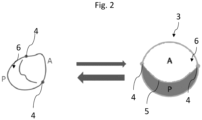
- Fig. 1 is a schematic diagram of a visualisation of a 3D valve model 2 of a heart valve, and a topology-based 2D model 3 according to an embodiment of the present invention.
- the visualisation of a valve model in this case a 3D valve model 2
- This may usefully be overlaid on a visualisation, e.g. volume rendering of the segmented heart valve (not shown).
- the topology-based 2D model 3 is depicted.
- the 3D valve model may be derived from the heart valve segmented from a 3D or 4D volume data set.
- the topology-based 2D model 3 is created from the 3D valve model e.g.
- the 3D ring 12 is the closed curve of the 3D valve model 2.
- the commissure points 4 may be adjusted by the user via a user interface 10, such that the commissure points 4 correspond to a junction of the borderline of the leaflets 6 with the annulus 12.
- the topology-based 2D model 2 can be adjusted to fit the individual anatomy of the heart valve (e.g., the leaflets 6) and the corresponding 3D valve model is displayed on the visualisation of a segmented heart valve.
- the following changes may be made to the commissure points 4:
- a user may add, delete and/or shift commissure points 4 so as to adjust the topology-based 2D model 3 to the real heart valve depicted in the visualisation of a segmented heart valve.
- the labels of the leaflets 6 may be manually amended by the user.
- the centre of the topology-based 2D model 3 is a circle coaxial to the circular closed curve 9 of the topology-based 2D model 3.
- Within the centre circle a tag is provided which is indicative of a type of heart valve.
- the 2D sections 16 of the topology-based 2D model are labelled with an abbreviation of the name of the respective valve, such as P1, Ps, A and S.
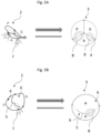
- Fig. 4 is a schematic visualisation of a topology-based 2D models being adjusted according to an embodiment of the present invention. That is, on the left side in Fig. 4 the initial topology-based 2D model 3 is depicted. Then, the user may grab a commissure point 4 with a pointing device 13 and drag the commissure point 4 in the desired direction along the model annulus or closed curve 9 (refer to the small arrow in Fig. 4 ). The adjustment to the commissure point 4 is preferably automatically applied to the 3D valve model (not depicted in Fig. 4 ), and the 3D valve model is displayed on the 4D Echo clip (i.e., the visualisation of a segmented heart valve 2).
- the complete topology-based 2D model 3 can be rotated to fit the alignment of the Echo clip.
- commissure points 4 can be added and removed in every sector of the topology-based 2D model 3 to fit the number and morphology of leaflets 6. Drag-and-drop of the commissure points 4 along the closed curve 9 adjusts the commissure points 4 on the Echo annulus 12.
- the leaflets 6 are labelled according to the nomenclature proposed by Hahn et. al. in case of the tricuspid valve.
- the selected morphology based on number and position of the commissure points 4 is mapped to the proposed nomenclature and a type is assigned in case of the tricuspid valve.
- the default type on initialization is the most common - Type I.
- a regurgitation flow is dynamically displayed for the period during which the valve is typically closed (mitral, tricuspid: systole, pulmonic, aortic: diastole). Then, a location of the corresponding area of leakage 8 on the topology-based 2D model 3 is displayed. In addition, the area size of the leakage 8 is shown scaled on the topology-based 2D model 3. Further, a magnitude of leakage through a heat map or contour graph (isolines) is displayed on the projection.
- the visualisation of the flow phenomena 7 in the topology-based 2D model 3 is realized by a marker 8 which might be changed with respect to its visualisation properties.
- the marker also represents a 2D section of the topology-based 2D 3 which is labelled with a physiological feature, namely a flow phenomenon.
- Fig. 6 shows a user interface 10 according to an embodiment of the invention.
- the segmented heart valve 2 and the topology-based 2D model 3 are depicted on a conventional computer screen 14.
- the screen 14 may comprise a panel 15 of buttons and sliders allowing the user to tilt, zoom, move or otherwise manipulate the segmented heart valve 2 and/or the topology-based 2D model 3.
- a 2D cut plane through the 3D or 4D volume data set may displayed, wherein at least one 3D region is depicted in a colour shading characteristic for the label of the respective 3D region (not shown).
- the display may be controlled by a computer 16, such as a PC, including a processor 17 and a hard disc 18.
- the user interface may have input tools such as a keyboard 19 and/or a mouse (i.e., a pointing device 20).
- Fig. 7 illustrates the projection of a valve model into the 3D or 4D volume data set 32 according to an embodiment of the invention.
- a topology-based 2D model 3 is visualised.
- This particular topology-based 2D model 3 includes three commissure points 4, named A, B and C, on a closed curve 9 (in this case a circle), centred around a centre point 22. It thus comprises three 2D regions 16, each representing one leaflet, and each 2D section 16 is surrounded by a segment of the closed curve 9 and two commissure lines 5.
- the topology-based 2D model 3 is derived from a corresponding 3D valve model 2.
- the 3D valve model 2 is visualised overlaid on a 3D echo clip 32, wherein the segmented heart valve is shown in a dynamic volume rendering view covering a time period of for example one or several heart cycles.
- the calculation illustrated at 34 is performed for each frame of the 4D volume data set (3D video clip).
- the projection direction illustrated by arrow 36 is calculated. This is done by first finding a plane 38 which best fits the 3D valve model 2, wherein the 3D valve model 2 in particular comprises a three-dimensional ring 12 representing the annulus, and a three-dimensional surface enclosed by the ring 12.
- the plane 38 is calculated to have the minimum square distance from this 3D surface.
- the 3D valve model 2 can be projected onto the plane 38, together with all 2D sections comprised therein, preferably using a parallel projection along projection direction 36. This results in a projected 3D valve model.
- the topology-based 2D model 3 can be positioned in the plane 38 and aligned with the 3D valve model 2, for example by aligning the positions of the centre points 22. From this plane 38, the valve model, in particular the projected 3D valve model or the topology-based 2D model 3, is projected into the respective frame of the 4D volume data set 32 along projection direction 36, as illustrated at 40.
- the 3D valve model 2 is projected directly along the projection direction 36, without first generating a projected 3D valve model.
- the projection of the 3D valve model 2 into the volume data set 32 results in a cylindrical volume-of-interest 42, which in this case has the complete height of the volume data set 32.
- the three 2D sections 16a, 16b, 16c are converted into 3D regions 26a, 26b, 26c, each shaped essentially like a slice of pie.
- the voxels in the volume data set 32 within each of these 3D regions 26a, 26b and 26c receive a different label, according to the 3D region in which they are located.
- each 3D region is illustrated as “dotted” for 3D region 26a, "horizontally ruled” for 3D region 26b, and “vertically ruled” for 3D region 26c.
- the 3D valve model may be projected only along a height which is not up to the complete height of the volume data set 32, but for example up to a pre-defined multiple of the diameter of the 3D ring 12 or closed curve of the 3D valve model 3.
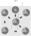
- Fig. 8 illustrates how the method of the invention may be used to generate visualisations in which voxels from different 3D regions are represented in different colours depending on their label.
- a plane 44 may be oriented in any orientation through the volume data set 32 and the volume-of-interest 42, which was generated by projection of the topology-based 2D model 3 along the projection direction 36 into the volume data set 32.
- the orientation of plane 44 may be adjusted by the user according to his/her needs, in order to obtain a good view through the volume data set.
- a corresponding cut plane 44 may be generated by means of multi-planar construction from the volume data set 32.
- the 2D cut plane 44 as illustrated in Fig.
Landscapes
- Engineering & Computer Science (AREA)
- Physics & Mathematics (AREA)
- General Physics & Mathematics (AREA)
- Theoretical Computer Science (AREA)
- Health & Medical Sciences (AREA)
- Computer Vision & Pattern Recognition (AREA)
- General Health & Medical Sciences (AREA)
- Medical Informatics (AREA)
- Nuclear Medicine, Radiotherapy & Molecular Imaging (AREA)
- Radiology & Medical Imaging (AREA)
- Quality & Reliability (AREA)
- Epidemiology (AREA)
- Primary Health Care (AREA)
- Public Health (AREA)
- Architecture (AREA)
- Computer Graphics (AREA)
- Computer Hardware Design (AREA)
- General Engineering & Computer Science (AREA)
- Software Systems (AREA)
- Ultra Sonic Daignosis Equipment (AREA)
Priority Applications (2)
| Application Number | Priority Date | Filing Date | Title |
|---|---|---|---|
| EP23202665.8A EP4538982A1 (de) | 2023-10-10 | 2023-10-10 | Computerimplementiertes verfahren zur analyse einer herzklappe, computerprogramm und system |
| PCT/EP2024/077723 WO2025078242A1 (en) | 2023-10-10 | 2024-10-02 | Computer implemented method for analysing a heart valve, computer program and system |
Applications Claiming Priority (1)
| Application Number | Priority Date | Filing Date | Title |
|---|---|---|---|
| EP23202665.8A EP4538982A1 (de) | 2023-10-10 | 2023-10-10 | Computerimplementiertes verfahren zur analyse einer herzklappe, computerprogramm und system |
Publications (1)
| Publication Number | Publication Date |
|---|---|
| EP4538982A1 true EP4538982A1 (de) | 2025-04-16 |
Family
ID=88315672
Family Applications (1)
| Application Number | Title | Priority Date | Filing Date |
|---|---|---|---|
| EP23202665.8A Withdrawn EP4538982A1 (de) | 2023-10-10 | 2023-10-10 | Computerimplementiertes verfahren zur analyse einer herzklappe, computerprogramm und system |
Country Status (2)
| Country | Link |
|---|---|
| EP (1) | EP4538982A1 (de) |
| WO (1) | WO2025078242A1 (de) |
Citations (4)
| Publication number | Priority date | Publication date | Assignee | Title |
|---|---|---|---|---|
| US20050187461A1 (en) | 2004-01-30 | 2005-08-25 | Gregory Murphy | System and method for facilitating cardiac intervention |
| US20180092690A1 (en) * | 2016-10-05 | 2018-04-05 | Arizona Board Of Regents On Behalf Of Arizona State University | Customized endovascular devices and methods pertaining thereto |
| US20200082531A1 (en) | 2018-09-07 | 2020-03-12 | 3Mensio Medical Imaging B.V. | Method, Device and System for Dynamic Analysis from Sequences of Volumetric Images |
| EP3683773A1 (de) * | 2019-01-17 | 2020-07-22 | Koninklijke Philips N.V. | Verfahren zur visualisierung einer dynamischen anatomischen struktur |
-
2023
- 2023-10-10 EP EP23202665.8A patent/EP4538982A1/de not_active Withdrawn
-
2024
- 2024-10-02 WO PCT/EP2024/077723 patent/WO2025078242A1/en active Pending
Patent Citations (4)
| Publication number | Priority date | Publication date | Assignee | Title |
|---|---|---|---|---|
| US20050187461A1 (en) | 2004-01-30 | 2005-08-25 | Gregory Murphy | System and method for facilitating cardiac intervention |
| US20180092690A1 (en) * | 2016-10-05 | 2018-04-05 | Arizona Board Of Regents On Behalf Of Arizona State University | Customized endovascular devices and methods pertaining thereto |
| US20200082531A1 (en) | 2018-09-07 | 2020-03-12 | 3Mensio Medical Imaging B.V. | Method, Device and System for Dynamic Analysis from Sequences of Volumetric Images |
| EP3683773A1 (de) * | 2019-01-17 | 2020-07-22 | Koninklijke Philips N.V. | Verfahren zur visualisierung einer dynamischen anatomischen struktur |
Non-Patent Citations (4)
| Title |
|---|
| DROGEHANNAH ET AL.: "Mitral Valve Segmentation Using Robust Nonnegative Matrix Factorization", JOURNAL OF IMAGING, vol. 7, no. 10, 2021, pages 213 |
| HAHN REBECCA T. ET AL: "Proposal for a Standard Echocardiographic Tricuspid Valve Nomenclature", JACC: CARDIOVASCULAR IMAGING, vol. 14, no. 7, July 2021 (2021-07-01), AMSTERDAM, NL, pages 1299 - 1305, XP093143295, ISSN: 1936-878X, DOI: 10.1016/j.jcmg.2021.01.012 * |
| REBECCA T. HAHNT. WECKBACHTHILO NOACKNADIRA HAMIDMITSUNOBU KITAMURARICHARD BAEPHILIPP LURZSUSHEEL K. KODALIPAUL SORAJJAJORG HAUSLE: "Proposal for a Standard Echocardiographic Tricuspid Valve Nomenclature", JACC: CARDIOVASCULAR IMAGING, vol. 14, 2021, pages 1299 - 1305 |
| TOMMASO MANSI ET AL., QUANTIFYING HEART VALVES: FROM DIAGNOSTIC TO PERSONALIZED VALVE REPAIR, April 2016 (2016-04-01) |
Also Published As
| Publication number | Publication date |
|---|---|
| WO2025078242A1 (en) | 2025-04-17 |
Similar Documents
| Publication | Publication Date | Title |
|---|---|---|
| CN113302660B (zh) | 对动态解剖结构进行可视化的方法 | |
| JP6670595B2 (ja) | 医用画像処理装置 | |
| US11547499B2 (en) | Dynamic and interactive navigation in a surgical environment | |
| US6151404A (en) | Anatomical visualization system | |
| CN106663309B (zh) | 用于医学成像中的用户引导的骨骼分段的方法和存储介质 | |
| US8077948B2 (en) | Method for editing 3D image segmentation maps | |
| US20050228250A1 (en) | System and method for visualization and navigation of three-dimensional medical images | |
| US20240394996A1 (en) | Method for analysing 3d medical image data, computer program and 3d medical image data evaluation device | |
| US20070116334A1 (en) | Method and apparatus for three-dimensional interactive tools for semi-automatic segmentation and editing of image objects | |
| EP3759684B1 (de) | Eingeschränkte objektkorrektur für ein segmentiertes bild | |
| Sørensen et al. | A new virtual reality approach for planning of cardiac interventions | |
| EP0836729A2 (de) | Anatomisches anzeigesystem | |
| JP2024516930A (ja) | 少なくとも1つのインターフェースにおいて対象物の少なくともゾーンを可視化するための方法 | |
| EP4538982A1 (de) | Computerimplementiertes verfahren zur analyse einer herzklappe, computerprogramm und system | |
| US20250363748A1 (en) | Computer implemented method for adjusting a morphology of a heart valve model, computer program and system | |
| Preim et al. | Smart 3d visualizations in clinical applications | |
| Montilla et al. | Computer assisted planning using dependent texture mapping and multiple rendering projections in medical applications | |
| EP4524900A1 (de) | Verfahren und system zur verbesserten interaktion mit medizinischer 2d- und 3d-visualisierung | |
| Udupa | 1 3D Imaging | |
| Rinaldi et al. | Computed Tomography: Device and Strategy Planning | |
| RU2684760C1 (ru) | Способ и система предоперационного моделирования медицинской процедуры | |
| Hansen | Software Assistance for Preoperative Risk Assessment and Intraoperative Support in Liver Resection Surgery | |
| Khundi et al. | Three-Dimensional Measurement and Visualisation of Spine as Assistive Intervention Tool When Diagnosing and Treating Scoliosis: New Method |
Legal Events
| Date | Code | Title | Description |
|---|---|---|---|
| PUAI | Public reference made under article 153(3) epc to a published international application that has entered the european phase |
Free format text: ORIGINAL CODE: 0009012 |
|
| STAA | Information on the status of an ep patent application or granted ep patent |
Free format text: STATUS: THE APPLICATION HAS BEEN PUBLISHED |
|
| AK | Designated contracting states |
Kind code of ref document: A1 Designated state(s): AL AT BE BG CH CY CZ DE DK EE ES FI FR GB GR HR HU IE IS IT LI LT LU LV MC ME MK MT NL NO PL PT RO RS SE SI SK SM TR |
|
| STAA | Information on the status of an ep patent application or granted ep patent |
Free format text: STATUS: THE APPLICATION IS DEEMED TO BE WITHDRAWN |
|
| 18D | Application deemed to be withdrawn |
Effective date: 20251017 |