EP4539052A1 - Substrat d'affichage et son procédé de fabrication, et appareil d'affichage - Google Patents
Substrat d'affichage et son procédé de fabrication, et appareil d'affichage Download PDFInfo
- Publication number
- EP4539052A1 EP4539052A1 EP25154964.8A EP25154964A EP4539052A1 EP 4539052 A1 EP4539052 A1 EP 4539052A1 EP 25154964 A EP25154964 A EP 25154964A EP 4539052 A1 EP4539052 A1 EP 4539052A1
- Authority
- EP
- European Patent Office
- Prior art keywords
- transistor
- base substrate
- node
- orthographic projection
- clock signal
- Prior art date
- Legal status (The legal status is an assumption and is not a legal conclusion. Google has not performed a legal analysis and makes no representation as to the accuracy of the status listed.)
- Pending
Links
Images


Classifications
-
- G—PHYSICS
- G09—EDUCATION; CRYPTOGRAPHY; DISPLAY; ADVERTISING; SEALS
- G09G—ARRANGEMENTS OR CIRCUITS FOR CONTROL OF INDICATING DEVICES USING STATIC MEANS TO PRESENT VARIABLE INFORMATION
- G09G3/00—Control arrangements or circuits, of interest only in connection with visual indicators other than cathode-ray tubes
- G09G3/20—Control arrangements or circuits, of interest only in connection with visual indicators other than cathode-ray tubes for presentation of an assembly of a number of characters, e.g. a page, by composing the assembly by combination of individual elements arranged in a matrix no fixed position being assigned to or needed to be assigned to the individual characters or partial characters
- G09G3/22—Control arrangements or circuits, of interest only in connection with visual indicators other than cathode-ray tubes for presentation of an assembly of a number of characters, e.g. a page, by composing the assembly by combination of individual elements arranged in a matrix no fixed position being assigned to or needed to be assigned to the individual characters or partial characters using controlled light sources
- G09G3/30—Control arrangements or circuits, of interest only in connection with visual indicators other than cathode-ray tubes for presentation of an assembly of a number of characters, e.g. a page, by composing the assembly by combination of individual elements arranged in a matrix no fixed position being assigned to or needed to be assigned to the individual characters or partial characters using controlled light sources using electroluminescent panels
- G09G3/32—Control arrangements or circuits, of interest only in connection with visual indicators other than cathode-ray tubes for presentation of an assembly of a number of characters, e.g. a page, by composing the assembly by combination of individual elements arranged in a matrix no fixed position being assigned to or needed to be assigned to the individual characters or partial characters using controlled light sources using electroluminescent panels semiconductive, e.g. using light-emitting diodes [LED]
- G09G3/3208—Control arrangements or circuits, of interest only in connection with visual indicators other than cathode-ray tubes for presentation of an assembly of a number of characters, e.g. a page, by composing the assembly by combination of individual elements arranged in a matrix no fixed position being assigned to or needed to be assigned to the individual characters or partial characters using controlled light sources using electroluminescent panels semiconductive, e.g. using light-emitting diodes [LED] organic, e.g. using organic light-emitting diodes [OLED]
- G09G3/3266—Details of drivers for scan electrodes
-
- G—PHYSICS
- G11—INFORMATION STORAGE
- G11C—STATIC STORES
- G11C19/00—Digital stores in which the information is moved stepwise, e.g. shift registers
- G11C19/28—Digital stores in which the information is moved stepwise, e.g. shift registers using semiconductor elements
-
- G—PHYSICS
- G09—EDUCATION; CRYPTOGRAPHY; DISPLAY; ADVERTISING; SEALS
- G09G—ARRANGEMENTS OR CIRCUITS FOR CONTROL OF INDICATING DEVICES USING STATIC MEANS TO PRESENT VARIABLE INFORMATION
- G09G2230/00—Details of flat display driving waveforms
-
- G—PHYSICS
- G09—EDUCATION; CRYPTOGRAPHY; DISPLAY; ADVERTISING; SEALS
- G09G—ARRANGEMENTS OR CIRCUITS FOR CONTROL OF INDICATING DEVICES USING STATIC MEANS TO PRESENT VARIABLE INFORMATION
- G09G2300/00—Aspects of the constitution of display devices
- G09G2300/04—Structural and physical details of display devices
- G09G2300/0404—Matrix technologies
- G09G2300/0408—Integration of the drivers onto the display substrate
-
- G—PHYSICS
- G09—EDUCATION; CRYPTOGRAPHY; DISPLAY; ADVERTISING; SEALS
- G09G—ARRANGEMENTS OR CIRCUITS FOR CONTROL OF INDICATING DEVICES USING STATIC MEANS TO PRESENT VARIABLE INFORMATION
- G09G2300/00—Aspects of the constitution of display devices
- G09G2300/04—Structural and physical details of display devices
- G09G2300/0421—Structural details of the set of electrodes
- G09G2300/0426—Layout of electrodes and connections
-
- G—PHYSICS
- G09—EDUCATION; CRYPTOGRAPHY; DISPLAY; ADVERTISING; SEALS
- G09G—ARRANGEMENTS OR CIRCUITS FOR CONTROL OF INDICATING DEVICES USING STATIC MEANS TO PRESENT VARIABLE INFORMATION
- G09G2310/00—Command of the display device
- G09G2310/02—Addressing, scanning or driving the display screen or processing steps related thereto
- G09G2310/0264—Details of driving circuits
- G09G2310/0286—Details of a shift registers arranged for use in a driving circuit
-
- G—PHYSICS
- G09—EDUCATION; CRYPTOGRAPHY; DISPLAY; ADVERTISING; SEALS
- G09G—ARRANGEMENTS OR CIRCUITS FOR CONTROL OF INDICATING DEVICES USING STATIC MEANS TO PRESENT VARIABLE INFORMATION
- G09G2310/00—Command of the display device
- G09G2310/06—Details of flat display driving waveforms
- G09G2310/061—Details of flat display driving waveforms for resetting or blanking
-
- H—ELECTRICITY
- H10—SEMICONDUCTOR DEVICES; ELECTRIC SOLID-STATE DEVICES NOT OTHERWISE PROVIDED FOR
- H10D—INORGANIC ELECTRIC SEMICONDUCTOR DEVICES
- H10D62/00—Semiconductor bodies, or regions thereof, of devices having potential barriers
- H10D62/10—Shapes, relative sizes or dispositions of the regions of the semiconductor bodies; Shapes of the semiconductor bodies
- H10D62/17—Semiconductor regions connected to electrodes not carrying current to be rectified, amplified or switched, e.g. channel regions
- H10D62/213—Channel regions of field-effect devices
- H10D62/221—Channel regions of field-effect devices of FETs
- H10D62/235—Channel regions of field-effect devices of FETs of IGFETs
- H10D62/299—Channel regions of field-effect devices of FETs of IGFETs having lateral doping variations
-
- H—ELECTRICITY
- H10—SEMICONDUCTOR DEVICES; ELECTRIC SOLID-STATE DEVICES NOT OTHERWISE PROVIDED FOR
- H10D—INORGANIC ELECTRIC SEMICONDUCTOR DEVICES
- H10D84/00—Integrated devices formed in or on semiconductor substrates that comprise only semiconducting layers, e.g. on Si wafers or on GaAs-on-Si wafers
- H10D84/01—Manufacture or treatment
-
- H—ELECTRICITY
- H10—SEMICONDUCTOR DEVICES; ELECTRIC SOLID-STATE DEVICES NOT OTHERWISE PROVIDED FOR
- H10D—INORGANIC ELECTRIC SEMICONDUCTOR DEVICES
- H10D86/00—Integrated devices formed in or on insulating or conducting substrates, e.g. formed in silicon-on-insulator [SOI] substrates or on stainless steel or glass substrates
Definitions
- the GOA including a plurality of shift register units which are cascaded may be adopted to provide voltage signals (scanning signals) of turn-on and turn-off states to the gate lines in the plurality of rows of the pixel array, so as to control the gate lines in the plurality of rows to be turned on in sequence.
- data signals are provided to pixel units in the corresponding row(s) of the pixel array through the data lines, so as to form gray scale voltages required by gray scales of a display image in respective pixel units, thereby displaying a frame of image.
- the first connection wire further includes a third portion, the third portion of the first connection wire is connected to and integrally formed with the first electrode of the first capacitor and a gate electrode of the output reset transistor, and the gate electrode of the output reset transistor includes a plurality of sub-gate electrodes arranged in parallel in the first direction.
- the second node control circuit further includes a second control transistor; an active layer of the second control transistor includes a first portion and a second portion which are integrally formed, the first portion of the active layer of the second control transistor extends along a direction different from the first direction, and the second portion of the active layer of the second control transistor extends along the first direction; and an orthographic projection of the active layer of the second control transistor on the base substrate is between the orthographic projection of the active layer of the input transistor on the base substrate and the orthographic projection of the active layer of the first control transistor on the base substrate.
- the display substrate provided by at least one embodiment of the present disclosure further includes a second connection wire in a substantially "Y" shape, the second connection wire is connected to and integrally formed with a gate electrode of the input transistor and a gate electrode of the second control transistor, a first terminal of the second connection wire is connected to the gate electrode of the input transistor, a second terminal of the second connection wire is connected to the gate electrode of the second control transistor, and a third terminal of the second connection wire is connected to the first clock signal line or the second clock signal line through a via hole penetrating through an insulating layer to receive the first clock signal.
- the display substrate provided by at least one embodiment of the present disclosure further includes a second transfer-connection electrode, a first terminal of the second transfer-connection electrode is connected to a second electrode of the first control transistor, and a gate electrode of the second control transistor is connected to a second terminal of the second transfer-connection electrode through a via hole penetrating through an insulating layer.
- the third node control circuit includes a third control transistor and a second capacitor; an orthographic projection of an active layer of the third control transistor on the base substrate and an orthographic projection of the second capacitor on the base substrate are on a side of the orthographic projection of the active layer of the first control transistor on the base substrate close to the display region, and the orthographic projection of the second capacitor on the base substrate is on a side of the orthographic projection of the active layer of the third control transistor on the base substrate away from the orthographic projection of the first capacitor on the base substrate; and a gate electrode of the third control transistor extends along a second direction different from the first direction, and the active layer of the third control transistor extends along the first direction.
- an orthographic projection of the first electrode of the first capacitor on the base substrate has a stepped shape in the first direction, and has a protrusion protruding along the second direction as a gate electrode of the first noise reduction transistor.
- the fourth node control circuit includes a fourth control transistor, and an orthographic projection of an active layer of the fourth control transistor on the base substrate is between the orthographic projection of the active layer of the third control transistor on the base substrate and the orthographic projection of the active layer of the first noise reduction transistor on the base substrate.
- the display substrate provided by at least one embodiment of the present disclosure further includes a fourth transfer-connection electrode and a first connection electrode;
- the fourth transfer-connection electrode is connected to a first electrode of the third control transistor, a gate electrode of the fourth control transistor is connected to the fourth transfer-connection electrode through a via hole penetrating through an insulating layer, and a second electrode of the first capacitor is connected to the fourth transfer-connection electrode through a via hole penetrating through an insulating layer;
- the first connection electrode and the second electrode of the first capacitor are in an identical layer, a first terminal of the first connection electrode is connected to the first clock signal line or the second clock signal line through a via hole penetrating through an insulating layer to receive the second clock signal, and a second terminal of the first connection electrode is connected to the fourth transfer-connection electrode through a via hole penetrating through an insulating layer.
- the second power line includes a protrusion protruding away from the display region in the second direction, and a second electrode of the first noise reduction transistor is connected to the protrusion of the second power line.
- an orthographic projection of the first clock signal line on the base substrate and an orthographic projection of the second clock signal line on the base substrate are on a side of the orthographic projection of the first power line on the base substrate away from the display region.
- the display device is an organic light-emitting diode display device.
- an output signal output by an output circuit of one shift register unit is correspondingly output to two rows of pixel units.
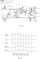
- FIG. 1A is a schematic diagram of an overall circuit architecture of a display panel.
- 101 represents an overall outer frame line of a display panel.
- the display panel includes a display region (i.e., a pixel array region) 102 and a peripheral region 106 located around the display region 102.
- the display region 102 includes pixel units 103 which are arranged in an array.
- the peripheral region 106 includes a scan driving shift register unit 104, a plurality of scan driving shift register units 104 which are cascaded form a gate driving circuit (a gate GOA), and the gate driving circuit is configured to provide such as gate scanning signals which are shifted row by row to the pixel units 103 arranged in an array in the display region 102 of the display panel 101.
- a gate GOA gate driving circuit
- the output signal output by the output circuit of one shift register unit 104 is correspondingly output to two rows of pixel units 103.
- FIG. 1B is a circuit diagram of a light-emitting control shift register unit.
- FIG. 1C is a signal timing diagram of the light-emitting control shift register unit illustrated in FIG. 1B in operation. In the following, the operation process of the light-emitting control shift register unit is briefly described with reference to FIG. 1B and FIG. 1C .
- the light-emitting control shift register unit 105 includes ten transistors (an input transistor T1, a first control transistor T2, a second control transistor T3, a second noise reduction transistor T4, a third noise reduction transistor T5, a third control transistor T6, a fourth control transistor T7, a first noise reduction transistor T8, an output transistor T9, and an output reset transistor T10) and three capacitors (a first capacitor C1, a second capacitor C2, and a third capacitor C3).
- the second electrode of the input transistor T1 in the first light-emitting control shift register unit 105 is connected to the input terminal EI
- the input terminal EI is configured to be connected to a trigger signal line ESTV to receive a trigger signal serving as the input signal
- the second electrode of the input transistor T1 in each other light-emitting control shift register unit 105 is electrically connected to the output terminal EOUT of the previous light-emitting control shift register unit 105 to receive the output signal, serving as the input signal, output by the output terminal EOUT of the previous light-emitting control shift register unit 105, so as to achieve shift output and provide such as the light-emitting control signals which are shifted row by row to the pixel units 103 arranged in an array in the display region 102 of the display panel 101.
- the light-emitting control shift register unit further includes a first clock signal terminal CK and a second clock signal terminal CB.
- ECK represents a first clock signal line
- ECB represents a second clock signal line.
- the first clock signal terminal CK is connected to the first clock signal line ECK or the second clock signal line ECB to receive a first clock signal.
- the first clock signal line ECK provides the first clock signal; and in the case where the first clock signal terminal CK is connected to the second clock signal line ECB, the second clock signal line ECB provides the first clock signal.
- a gate electrode of the first control transistor T2 is connected to the first node N1, a first electrode of the first control transistor T2 is connected to the second node N2, and a second electrode of the first control transistor T2 is connected to the first clock signal terminal CK to receive the first clock signal.
- a gate electrode of the second noise reduction transistor T4 is connected to the second clock signal terminal CB (for example, the second clock signal terminal CB is connected to the first clock signal line ECK) to receive the second clock signal, a first electrode of the second noise reduction transistor T4 is connected to the first node N1, and a second electrode of the second noise reduction transistor T4 is connected to a second electrode of the third noise reduction transistor T5.
- a first electrode of the third capacitor C3 is connected to the fourth node N4, and a second electrode of the third capacitor C3 is connected to the second power line VGH to receive the second voltage.
- each transistor in the light-emitting control shift register unit 105 illustrated in FIG. 1B is described by taking a P-type transistor as an example, that is, each transistor is turned on in the case where the gate electrode of the transistor is provided with a low electrical level (a turned-on electrical level), and the transistor is turned off in the case where the gate electrode of the transistor is provided with a high electrical level (a turned-off electrical level).
- the first electrode of the transistor may be a source electrode
- the second electrode of the transistor may be a drain electrode.
- the second clock signal line ECB provides a low electrical level, and therefore, the first clock signal terminal CK connected to the second clock signal line ECB receives the first clock signal with a low electrical level.
- the input transistor T1 and the second control transistor T3 are turned on, the input transistor T1 that is turned on enables the trigger signal ESTV with a high electrical level to be transmitted to the first node N1, so as to change the level of the first node N1 into a high electrical level, and thus the first control transistor T2, the first noise reduction transistor T8, and the output reset transistor T10 are turned off.
- the second clock signal line ECB provides the first clock signal with a low electrical level to the first clock signal terminal CK, and thus the input transistor T1 and the second control transistor T3 are turned on.
- the first clock signal line ECK provides the second clock signal with a high electrical level to the second clock signal terminal CB, and thus the second noise reduction transistor T4 and the fourth control transistor T7 are turned off.
- the input transistor T1 that is turned on enables the trigger signal ESTV with a low electrical level to be transmitted to the first node N1, so as to change the level of the first node N1 into a low electrical level.
- the first control transistor T2 that is turned on enables the first clock signal with a low electrical level to be transmitted to the second node N2, so as to further pull down the level of the second node N2, and thus the level of the second node N2 continues to be kept being the low electrical level of the previous phase, so as to enable the third noise reduction transistor T5 and the third control transistor T6 to be turned on.
- the first noise reduction transistor T8 that is turned on enables the second voltage VGH with a high electrical level to be transmitted to the fourth node N4, so as to change the level of the fourth node N4 into a high electrical level, and thus the output transistor T9 is turned off.
- the second clock signal line ECB provides the first clock signal with a high electrical level to the first clock signal terminal CK
- the first clock signal line ECK provides the second clock signal with a low electrical level to the second clock signal terminal CB, and thus the second noise reduction transistor T4 and the fourth control transistor T7 are turned on.
- the second clock signal is changed from a high electrical level in the fifth phase P5 into a low electrical level, and for example, the variation is ⁇ t (for example, being greater than 6V)
- the level of the first node N1 is changed from a low electrical level (for example, -4.5V) in the fifth phase P5 into a low electrical level (for example, -4.5V- ⁇ t) with an even lower voltage value.
- the output terminal EOUT_2 of the second light-emitting control shift register unit 105 outputs a low electrical level, for example, -3V (detailed descriptions may be referred to the operation process of the first light-emitting control shift register unit 105 in the fifth phase P5 described above).
- FIG. 1D is a schematic layout diagram of the light-emitting control shift register unit illustrated in FIG. 1B on a display substrate. It should be noted that, for clarity and conciseness, the first clock signal line ECK, the second clock signal line ECB, the trigger signal line ESTV, and the connection relationship among the above signal lines and respective transistors are not shown in FIG. 1D .
- the plurality of clock signal lines described above may also include a trigger signal line ESTV for providing a trigger signal.
- the orthographic projection of the trigger signal line ESTV on the base substrate 10 may be located on a side of the orthographic projection of the first clock signal line ECK and the second clock signal line ECB on the base substrate 10 away from the orthographic projection of the shift register unit 105 on the base substrate 10. That is, the trigger signal line ESTV, the first clock signal line ECK, and the second clock signal line ECB are sequentially arranged from the left to the right along the second direction X on the base substrate 10.
- the first clock signal terminal CK of the K-th shift register unit 105 (K is an even number that is greater than or equal to 2) is connected to the second clock signal line ECB to receive the first clock signal
- the second clock signal terminal CB of the K-th shift register unit 105 is connected to the first clock signal line ECK to receive the second clock signal
- the first clock signal terminal CK of the (K+1)-th shift register unit is connected to the first clock signal line ECK to receive the first clock signal
- the second clock signal terminal CB of the (K+1)-th shift register unit is connected to the second clock signal line ECB to receive the second clock signal.
- the second node control circuit 1043 is configured to input the first voltage or the first clock signal to the second node N2 under control of the first clock signal and the level of the first node N1, so as to control the level of the second node N2.
- the second node control circuit 1043 is connected to the first power line VGL1 (or the third power line VGL2), the first node N1, the first clock signal terminal CK, and the second node N2, and the second node control circuit 1043 is configured to be turned on under control of the first clock signal received by the first clock signal terminal CK and the level of the first node N1, so as to enable the first voltage provided by the first power line VGL1 or the first clock signal to be input to the second node N2 to control the level of the second node N2.
- the second node control circuit 1043 is implemented as the first control transistor T2 and the second control transistor T3 as described above, the connections for the first control transistor T2 and the second control transistor T3 may refer to the above description, and details are not described herein again.
- the second node control circuit 1043 is not limited to be connected to the first node N1, and may also be connected to other independent voltage terminals (which provide a voltage that is the same as the voltage at the first node N1), or be connected to a circuit that is the same as the input circuit and provided separately, and the embodiments of the present disclosure are not limited in this aspect.
- the connections for other circuits in the shift register unit are similar to that, and details are not described herein.
- the first node control circuit 1042 is configured to input the second voltage to the first node N1 under control of the second clock signal and the level of the second node N2, so as to perform noise reduction on the first node N1.
- the first node control circuit 1042 is connected to the second power line VGH, the second clock signal terminal CB (the second clock signal terminal CB of the K-th shift register unit 105 is connected to the first clock signal line ECK to receive the second clock signal, and the second clock signal terminal CB of the (K+1)-th shift register unit is connected to the second clock signal line ECB to receive the second clock signal), the second node N2, and the first node N1, and the first node control circuit 1042 is configured to be turned on under control of the second clock signal received by the second clock signal terminal CB and the level of the second node N2, so as to enable the second power line VGH to be connected to the first node N1 to input the second voltage provided by the second power line VGH to the first node N1, thereby performing noise reduction on the first no
- the first node control circuit 1042 is implemented as the second noise reduction transistor T4 and the third noise reduction transistor T5 as described above, the connections for the second noise reduction transistor T4 and the third noise reduction transistor T5 may refer to the above descriptions, and details are not described herein again.
- the first node control circuit 1042 is not limited to be connected to the second node N2, and may also be connected to other independent voltage terminals (which provide a voltage that is the same as the voltage at the second node N2), or be connected to a circuit that is the same as the second node control circuit 1043 and provided separately, and the embodiments of the present disclosure are not limited in this aspect.
- the connections for other circuits in the shift register unit are similar to that, and details are not described herein.
- the output circuit 1046 is configured to output the second voltage to the output terminal EOUT under control of the level of the fourth node N4.
- the output circuit 1046 is connected to the fourth node N4, the output terminal EOUT, and the second power line VGH, and is configured to be turned on under control of the level of the fourth node N4, so as to connect the second power line VGH and the output terminal EOUT, so that the second voltage is output at the output terminal EOUT and serves as the output signal.
- the output circuit 1046 is implemented as the output transistor T9 and the third capacitor C3 as described above, the connections for the output transistor T9 and the third capacitor C3 may refer to the above descriptions, and details are not described herein again.
- the output circuit 1046 is not limited to be connected to the fourth node N4, and may also be connected to other independent voltage terminals (which provide a voltage that is the same as the voltage at the fourth node N4) or be connected to a circuit that is the same as the fourth node control circuit 1045 and provided separately, and the embodiments of the present disclosure are not limited in this aspect.
- the connections for other circuits in the shift register unit are similar to that, and details are not described herein.
- the output reset circuit 1047 is configured to reset the output terminal EOUT under control of the level of the first node N1.
- the output reset circuit 1047 is connected to the second clock signal terminal CB, the first node N1, the third power line VGL2 (or the first power line VGL1), and the output terminal EOUT, and the output reset circuit 1047 is configured to be turned on under control of the level of the first node N1 to enable the third power line VGL2 to be connected to the output terminal EOUT, so as to control the level of the output terminal EOUT to be a low electrical level, thereby avoiding the incorrect output during the non-output phase caused by the shift register unit 105.
- the fourth node noise reduction circuit 1048 is configured to perform noise reduction on the fourth node N4 under control of the level of the first node N1.
- the fourth node noise reduction circuit 1048 is connected to the second power line VGH, the first node N1, and the fourth node N4, and is configured to be turned on under control of the level of the first node N1 to enable the fourth node N4 to be connected to the second power line VGH, so as to keep the voltage of the fourth node N4 at a high electrical level to perform noise reduction on the fourth node N4, thereby avoiding the incorrect output during the non-output phase caused by the shift register unit 105.
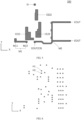
- FIG. 7 is a planar diagram of a third conductive layer of a display substrate provided by at least one embodiment of the present disclosure.
- FIG. 8 is a cross-sectional view of the display substrate illustrated in FIG. 2 along an A-A' direction in some examples.
- the laminated structure of the display substrate provided by at least one embodiment of the present disclosure is described in detail with reference to FIG. 3 to FIG. 8 .
- the via hole as illustrated in FIG. 6 is a via hole penetrating through one or more layers of the first insulating layer 350, the second insulating layer 360, and the third insulating layer 370.
- the materials of the first insulating layer 350, the second insulating layer 360, the third insulating layer 370, and the fourth insulating layer 380 may include such as an inorganic insulating material, for example, SiNx, SiOx, SiNxOy, or the like, and may also include such as an organic insulating material, for example, organic resin or the like, or other suitable materials, and the embodiments of the present disclosure are not limited in this aspect.
- the display substrate as illustrated in FIG. 2 is described by taking the layout design for the K-th shift register unit in the light-emitting control driving circuit array, and the first power line, the second power line, the third power line, and the clock signal lines which are connected to the K-th shift register unit as an example
- the implementation of the layout for other shift register units may refer to the layout design as illustrated in FIG. 2 , and details are not described herein.
- other suitable layouts may also be adopted, and the embodiments of the present disclosure are not limited in this aspect.
- the layout of the shift register unit in each other light-emitting control driving circuit array may also refer to the layout illustrated in FIG. 2 , or may adopt other suitable methods, and the embodiments of the present disclosure are not limited in this aspect.
- the active layers A1 to A10 of the input transistor T1 to the output reset transistor T10 of the shift register unit 105 as illustrated in FIG. 2 may be formed in the semiconductor layer 310 as illustrated in FIG. 3 .
- the semiconductor layer 310 may be formed through a patterning process for a semiconductor material.
- the semiconductor layer 310 may include a part with a rod-like shape or a part with a curved or bent shape, so as to be used for forming the active layers A1 to A10 of the input transistor T1 to the output reset transistor T10 described above.
- the active layer of each transistor may include a source electrode region, a drain electrode region, and a channel region between the source electrode region and the drain electrode region.
- the channel region has the semiconductor characteristics
- the source electrode region and the drain electrode region are on two sides of the channel region and may be doped with impurities, and thus the source electrode region and the drain electrode region are conductive.
- the source electrode region is a part of the active layer, and the metal electrode (for example, in the third conductive layer 340) in contact with the source electrode region corresponds to the source electrode (or referred to as the first electrode) of the transistor; and the drain electrode region is a part of the active layer, the metal electrode (for example, in the third conductive layer 340) in contact with the drain electrode region corresponds to the drain electrode (or referred to as the second electrode) of the transistor.
- the source electrode region is connected to the corresponding metal electrode (the source electrode) through a via hole penetrating through the first insulating layer 350, the second insulating layer 360, and the third insulating layer 370
- the drain electrode region is connected to the corresponding metal electrode (the drain electrode) through a via hole penetrating through the first insulating layer 350, the second insulating layer 360, and the third insulating layer 370.
- the gate electrodes G1 to G10 of the input transistor T1 to the output reset transistor T10 are portions which are circled by a circular or oval dotted line, that is, the gate electrodes are portions, which overlap with semiconductor layer structures of the transistors, of electrodes or wires in the first conductive layer 320.
- FIG. 5 illustrates the second conductive layer 330 of the display substrate, and the second conductive layer 330 includes the second electrodes CE21, CE22, CE23 of the first capacitor C1 to the third capacitor C3, and connection electrodes (e.g., a first connection electrode M1 and a second connection electrode M2) for connecting with such as signal lines or transfer-connection electrodes in the third conductive layer 340.
- the second electrode CE21 at least partially overlaps with the first electrode CE11 to form the first capacitor C1
- the second electrode CE22 at least partially overlaps with the first electrode CE12 to form the second capacitor C2
- the second electrode CE23 at least partially overlaps with the first electrode CE13 to form the third capacitor C3.
- the second connection electrode M2 includes the output terminal EOUT.
- the second conductive layer 330 further includes the input terminal EI.
- the second connection electrode M2 located in the second conductive layer 330 can be used to provide the output signal.
- the output signal of the output terminal EOUT of the shift register unit 105 can also be provided by an electrode located in other layers, that is, the output terminal EOUT may also be provided in other layers different from the second conductive layer 330, for example, provided in the first conductive layer 320.
- the embodiments of the present disclosure are not limited in this aspect.
- the third conductive layer 340 further includes a first transfer-connection electrode 110, a second transfer-connection electrode 120, a third transfer-connection electrode 130, a fourth transfer-connection electrode 140, a fifth transfer-connection electrode 150, a sixth transfer-connection electrode 160, a seventh transfer-connection electrode 170, an eighth transfer-connection electrode 180, a ninth transfer-connection electrode 190, or the like, which are used for connecting the transistors, capacitors, and signal lines.
- the ninth transfer-connection electrode 190 may be connected to the input terminal EI in the second conductive layer 330 through a via hole structure.
- the input terminal EI of the shift register unit 105 may also be located in other layers, for example, located in the third conductive layer 340 to be directly connected to the ninth transfer-connection electrode 190.
- the ninth transfer-connection electrode 190 may be integrally formed with the input terminal EI, for example, the ninth transfer-connection electrode 190 includes the input terminal EI, and the embodiments of the present disclosure are not limited in this aspect.
- the material of the above-mentioned third conductive layer 340 may include titanium, titanium alloy, aluminum, aluminum alloy, copper, copper alloy, or any other suitable composite materials, and the embodiments of the present disclosure are not limited in this aspect.
- the materials of the first conductive layer 320 and the second conductive layer 330 may be the same as the material of the third conductive layer 340, and details are not described herein.
- the first control transistor T2 includes a first gate electrode G21, that is, the gate electrode G2 of the first control transistor T2 includes the first gate electrode G21.
- the display substrate further includes a first connection wire L1, and the first connection wire L1 includes a first portion L11 and a second portion L12.
- the first portion L11 of the first connection wire L1 is connected to and integrally formed with the first gate electrode G21 of the first control transistor T2, the first portion L11 of the first connection wire L1 extends along the first direction Y, and the orthographic projection of the first portion L11 of the first connection wire L1 on the base substrate 10 is located on a side of the orthographic projection of the active layer A2 of the first control transistor T2 on the base substrate 10 away from the display region 102.
- the first portion L11 is located on the left side of the active layer A2 of the first control transistor T2.
- the second portion L12 of the first connection wire L1 is connected to and integrally formed with the first gate electrode G21 of the first control transistor T2.
- the second portion L12 of the first connection wire L1 extends along a direction, opposite to the extending direction of the first portion L11 of the first connection wire L1, in the first direction Y
- the included angle between the extending direction of the second portion L12 and the extending direction of the first portion L11 may range from 120 degrees to 180 degrees.
- the orthographic projection of the second portion L12 of the first connection wire L1 on the base substrate 10 is located on a side of the orthographic projection of the active layer A2 of the first control transistor T2 on the base substrate 10 close to the display region 102.
- the second portion L12 is located on the right side of the active layer A2 of the first control transistor T2.
- the included angle between the extending direction of the second portion L12 and the extending direction of the first portion L11 may be 120 degrees, 135 degrees, 160 degrees, 180 degrees, or the like, which may depend on the actual situation, and the embodiments of the present disclosure are not limited in this aspect.
- the size of the shift register unit 105 in the second direction X can be reduced to a certain extent, so that the size of the shift register unit 105 is reduced, which facilitates the narrow frame design of the display substrate, and further the display quality of the display substrate can be ensured.
- the first portion L11 of the first connection wire L1 on the left side of the active layer A2 of the first control transistor T2 in the second direction X that is, by arranging the first portion L11 of the first connection wire L1 on the side of the active layer A2 of the first control transistor T2 close to the signal line, more space can be reserved for other transistors, capacitors, wires, etc. in the shift register unit 105, so that the wire connection and structural layout of the shift register unit can be further optimized.
- the active layer of the first control transistor T2 may form a "U" shape structure, and the gate electrode of the first control transistor T2 may adopt a linear shape structure overlapping with the active layer in the "U" shape, so as to form the double-gate structure.
- the embodiments of the present disclosure are not limited in this aspect, as along as the arrangement of other structures is not adversely influenced and the size of the shift register unit is not increased too much. It should be noted that, the active layer of the first control transistor T2 may also overlap with one single gate electrode, and the embodiments of the present disclosure are not limited in this aspect.
- the orthographic projection of the active layer A10 of the output reset transistor T10 on the base substrate 10 is located on a side of the orthographic projection of the first capacitor C1 on the base substrate 10 close to the display region 102.
- the active layer A10 of the output reset transistor T10 is located on the right side of the first capacitor C1.
- the first connection wire L1 further includes a third portion L13, and the third portion L13 is connected to and integrally formed with the first electrode CE11 of the first capacitor C1 and the gate electrode G10 of the output reset transistor T10.
- the third portion L13 of the first connection wire L1 is located between the first electrode CE11 of the first capacitor C1 and the gate electrode G10 of the output reset transistor T10.
- the gate electrode G10 of the output reset transistor T10 includes a plurality of sub-gate electrodes arranged in parallel in the first direction Y
- the gate electrode G10 of the output reset transistor T10 is comb-shaped in the first direction Y to improve the stability of the output reset transistor T10.
- the active layer A1 of the input transistor T1 extends along the first direction Y
- the active layer A2 of the first control transistor T2 extends along the first direction Y
- the orthographic projection of the active layer A1 of the input transistor T1 on the base substrate 10 is located on a side of the orthographic projection of the active layer A2 of the first control transistor T2 on the base substrate 10 away from the orthographic projection of the first capacitor C1 on the base substrate 10 and close to the display region 102.
- the input transistor T1 is spatially located on the upper right side of the first control transistor T2 along the first direction Y
- the first transfer-connection electrode 110 may serve as the first node N1 in the circuit structure illustrated in FIG. 1B .
- the orthographic projection of the active layer A3 of the second control transistor T3 on the base substrate 10 is located between the orthographic projection of the active layer A1 of the input transistor T1 on the base substrate 10 and the orthographic projection of the active layer A2 of the first control transistor T2 on the base substrate 10.
- the third terminal L23 of the second connection wire L2 may also be connected to the first clock signal line CLK through a via hole penetrating through the second insulating layer 360 and the third insulating layer 370 to receive the first clock signal, and the embodiments of the present disclosure are not limited in this aspect.
- the first power line VGL1 is connected to the second electrode of the second control transistor T3, and the orthographic projection of the first power line VGL1 on the base substrate 10 is located on a side of the orthographic projection of the gate electrode G3 of the second control transistor T3 on the base substrate 10 away from the display region 102. That is, in the second direction X, the second control transistor T3 is located on the right side of the first power line VGL1.
- the orthographic projection of the active layer A6 of the third control transistor T6 on the base substrate 10 and the orthographic projection of the second capacitor C2 on the base substrate 10 are located on a side of the orthographic projection of the active layer A2 of the first control transistor T2 on the base substrate 10 close to the display region 102, and the orthographic projection of the second capacitor C2 on the base substrate 10 is located on a side of the orthographic projection of the active layer A6 of the third control transistor T6 on the base substrate 10 away from the orthographic projection of the first capacitor C1 on the base substrate 10.
- the gate electrode G6 of the third control transistor T6 extends along the second direction X different from the first direction Y, and the active layer of the third control transistor T6 extends along the first direction Y.
- the gate electrode G6 of the third control transistor T6 can be provided for the structural layout of the fourth control transistor T7 and the first noise reduction transistor T8 in the shift register unit 105, so as to further optimize the circuit connection and structural layout of the shift register unit 105, thereby reducing the size of the shift register unit 105 and further facilitating the narrow frame design of the display substrate.
- the active layer A6 of the third control transistor T6 can extend substantially along the first direction Y, and the gate electrode G6 of the third control transistor T6 can also be used as a part of the third connection wire L3, thereby reducing the space that needs to be occupied by the third control transistor T6 and further reducing the space that needs to be occupied by the third transfer-connection electrode 130 (for example, the third transfer-connection electrode 130 can serve as the second node N2 in the circuit structure illustrated in FIG. 1B ), so that the circuit connection and structural layout of the shift register unit 105 can be further optimized, and the size of the shift register unit 105 can be reduced, thereby facilitating the narrow frame design of the display substrate.
- the display substrate further includes a third connection wire L3, the third connection wire L3 is connected to and integrally formed with the first electrode CE12 of the second capacitor C2 and the gate electrode G6 of the third control transistor T6, and the first terminal L31 of the third connection wire L3 is connected to the first electrode CE12 of the second capacitor C2.
- the second terminal L32 of the third connection wire L3 is connected to the third transfer-connection electrode 130 through a via hole penetrating through the second insulating layer 360 and the third insulating layer 370, so that the gate electrode G6 of the third control transistor T6 can be connected with the first electrode of the first control transistor T2 and the first electrode of the second control transistor T3 located in a different layer (e.g., the third conductive layer 340).
- the third transfer-connection electrode 130 may serve as the second node N2 in the circuit structure illustrated in FIG. 1B . Therefore, in the case where the first connection wire L1 is provided to extend from the lower left side of the first control transistor T2 to the upper right side of the first control transistor T2, the transfer-connection hole corresponding to the second node N2 can no longer be arranged side by side with the second portion L12 of the first connection wire L1 along the second direction X, thereby further reducing the size of the shift register unit 105 in the second direction X and facilitating the narrow frame design of the display substrate.
- FIG. 1B the transfer-connection hole corresponding to the second node N2 can no longer be arranged side by side with the second portion L12 of the first connection wire L1 along the second direction X, thereby further reducing the size of the shift register unit 105 in the second direction X and facilitating the narrow frame design of the display substrate.
- the transfer-connection hole corresponding to the second node N2 can be compactly arranged in the gap between the first connection wire L1 and the third control transistor T6 in the second direction X, thereby further optimizing the circuit connection and structural layout of the shift register unit 105, reducing or avoiding the waste of space on the display substrate, and further reducing the size of the shift register unit 105 in the second direction X, so as to facilitate the narrow frame design of the display substrate.
- the orthographic projection of the first electrode CE11 of the first capacitor C1 on the base substrate 10 has a stepped shape in the first direction Y, and has a protrusion protruding along the second direction X as the gate electrode G8 of the first noise reduction transistor T8.
- the first electrode CE11 of the first capacitor C1 to have a stepped shape in the first direction Y, the size occupied by the first electrode CE11 of the first capacitor C1 in the second direction X can be reduced, thereby optimizing the circuit connection and structural layout of the shift register unit 105, and further reducing the size occupied by the shift register unit 105 in the second direction X to a certain extent.
- the orthographic projection of the active layer A7 of the fourth control transistor T7 on the base substrate 10 is located between the orthographic projection of the active layer A6 of the third control transistor T6 on the base substrate 10 and the orthographic projection of the active layer A8 of the first noise reduction transistor T8 on the base substrate 10.
- the active layer A6 of the third control transistor T6, the active layer A7 of the fourth control transistor T7, and the active layer A8 of the first noise reduction transistor T8 are located in a continuous first semiconductor layer A13.
- the active layer A6 of the third control transistor T6, the active layer A7 of the fourth control transistor T7, and the active layer A8 of the first noise reduction transistor T8 are integrally formed.
- the active layer A7 of the fourth control transistor T7 and the active layer A8 of the first noise reduction transistor T8 extend along the first direction Y
- the gate electrode G7 of the fourth control transistor T7 and the gate electrode G8 of the first noise reduction transistor T8 extend along the second direction X and are arranged side by side in the first direction X.
- the first electrode, the gate electrode and the second electrode of the third control transistor T6, the first electrode, the gate electrode and the second electrode of the fourth control transistor T7, and the first electrode, the gate electrode and the second electrode of the first noise reduction transistor T8 can be alternately arranged along the first direction Y, so that the layout arrangement of the third control transistor T6, the fourth control transistor T7, and the first noise reduction transistor T8 can be implemented in a relatively simple way.
- the total space occupied by the third control transistor T6, the fourth control transistor T7, and the first noise reduction transistor T8 in the display substrate can be relatively compressed.
- the total space occupied by the third control transistor T6, the fourth control transistor T7, and the first noise reduction transistor T8 in the display substrate can be minimized, so that the size occupied by the shift register unit 105 in the second direction X can be further compressed to a certain extent, thereby facilitating the narrow frame design of the display substrate.
- the display substrate further includes a fourth transfer-connection electrode 140 and a first connection electrode M1.
- the fourth transfer-connection electrode 140 is connected to the first electrode of the third control transistor T6, the gate electrode G7 of the fourth control transistor T7 is connected to the fourth transfer-connection electrode 140 through a via hole penetrating through the second insulating layer 360 and the third insulating layer 370, and the second electrode CE21 of the first capacitor C1 is connected to the fourth transfer-connection electrode 140 through a via hole penetrating through the third insulating layer 370.
- the first connection electrode M1 is located in the same layer as the second electrode CE21 of the first capacitor C1, the first terminal M11 of the first connection electrode M1 is connected to the first clock signal line CLK to receive the second clock signal through a via hole penetrating through the third insulating layer 370, and the second terminal M12 of the first connection electrode M1 is connected to the fourth transfer-connection electrode 140 through a via hole penetrating through the third insulating layer 370.
- the first terminal M11 of the first connection electrode M1 may also be connected to the second clock signal line CLB through a via hole penetrating through the third insulating layer 370 to receive the second clock signal, and the embodiments of the present disclosure are not limited in this aspect.
- the orthographic projection of the third capacitor C3 on the base substrate 10 and the orthographic projection of the second capacitor C2 on the base substrate 10 are arranged side by side in the first direction Y
- the orthographic projection of the third capacitor C3 on the base substrate 10 and the orthographic projection of the first capacitor C1 on the base substrate 10 are arranged side by side in the second direction X.
- the orthographic projection of the active layer A9 of the output transistor T9 on the base substrate 10 is located on a side of the orthographic projection of the second capacitor C2 on the base substrate 10 close to the display region 102, and the orthographic projection of the active layer of the output reset transistor T10 on the base substrate 10 is located on a side of the orthographic projection of the third capacitor C3 on the base substrate 10 close to the display region 102.
- a contour of a side of the orthographic projection of the first electrode CE13 of the third capacitor C3 on the base substrate 10 towards the orthographic projection of the second capacitor C2 on the base substrate 10 is stepped. Therefore, while the circuit connection and structural layout of the shift register unit 105 can be optimized, enough space can be reserved for the third capacitor C3, thereby improving the stability of the third capacitor C3.
- the active layer A9 of the output transistor T9 and the active layer A10 of the output reset transistor T10 are located in a continuous second semiconductor layer A12, that is, the active layer A9 of the output transistor T9 and the active layer A10 of the output reset transistor T10 are integrally formed.
- the gate electrode of the output transistor T9 and the gate electrode of the output reset transistor T10 are arranged side by side in the first direction Y.
- the gate electrode of the output transistor T9 and the gate electrode of the output reset transistor T10 may be parallel to each other, and for example, may both extend along the second direction X.
- the extending direction of the gate electrode of the output transistor T9 and the extending direction of the gate electrode of the output reset transistor T10 may not be parallel to each other, and for example, may intersect at a certain angle.
- the intersecting angle may be smaller than or equal to 20 degrees, or the range of the angle between the extending direction and the horizontal line may be smaller than or equal to 20 degrees, and the embodiments of the present disclosure are not limited in this aspect, as long as the gate electrode of the output transistor T9 and the gate electrode of the output reset transistor T10 are integrally provided and arranged up and down along the first direction Y.
- the orthographic projection of the gate electrode G10 of the output reset transistor T10 on the base substrate 10 is closer to the display region 102 than the orthographic projection of the gate electrode G9 of the output transistor T9 on the base substrate 10.
- the center of the orthographic projection of the gate electrode G10 of the output reset transistor T10 on the base substrate 10 is closer to the display region 102 than the center of the orthographic projection of the gate electrode G9 of the output transistor T9 on the base substrate 10.
- the size of the orthographic projection of the active layer A10 of the output reset transistor T10 on the base substrate 10 in the second direction X is smaller than the size of the orthographic projection of the active layer A9 of the output transistor T9 on the base substrate 10 in the second direction X.
- the display substrate further includes a fourth connection wire L4, a sixth transfer-connection electrode 160, and a second power line VGH for providing the second voltage.
- the orthographic projection of the second power line VGH on the base substrate 10 is located on a side of the orthographic projection of the second capacitor C2 on the base substrate 10 close to the display region 102.
- the orthographic projection of the third capacitor C3 on the base substrate 10 partially overlaps with the orthographic projection of the second power line VGH on the base substrate 10.
- the second electrode CE23 of the third capacitor C3 is connected to the second power line VGH through a via hole penetrating through the third insulating layer 370.
- the fourth connection wire L4 is connected to and integrally formed with the first electrode CE13 of the third capacitor C3 and the gate electrode G9 of the output transistor T9.
- the sixth transfer-connection electrode 160 includes a first portion 161 extending along the first direction Y and a second portion 162 which is integrally formed with the first portion 161 and extends along the second direction X.
- the second portion 162 of the sixth transfer-connection electrode 160 is connected to the second electrode of the fourth control transistor T7 and the first electrode of the first noise reduction transistor T8.
- the first electrode CE13 of the third capacitor C3 is connected to the first portion 161 of the sixth transfer-connection electrode 160 through a via hole penetrating through the second insulating layer 360 and the third insulating layer 370.
- the display substrate further includes a seventh transfer-connection electrode 170, an eighth transfer-connection electrode 180, and a second connection electrode M2.
- the seventh transfer-connection electrode 170 is connected to the second electrode of the output transistor T9
- the eighth transfer-connection electrode 180 is connected to the second electrode of the output reset transistor T10.
- the second connection electrode M2 is located in the same layer as the second electrode CE21 of the first capacitor C1, and the seventh transfer-connection electrode 170 and the eighth transfer-connection electrode 180 are respectively connected to the second connection electrode M2 through via holes penetrating through the third insulating layer 370, so that the second electrode of the output transistor T9 and the second electrode of the output reset transistor T10 are both connected to the second connection electrode M2 (i.e., the output terminal EOUT), thereby implementing the output of the output signal and the reset of the output terminal EOUT.
- the second connection electrode M2 is connected to the gate line as the output terminal EOUT, so as to output the output signal of the output terminal EOUT to the pixel unit 103 of the display region 102.
- the second connection electrode M2 may have two output terminals EOUT for providing output signals to the pixel units 103 in two adjacent rows of the display region 102.
- the two output terminals EOUT are arranged side by side in the first direction Y
- the second connection electrode M2 may also have still another output terminal EOUT (e.g., the output terminal CR illustrated in FIG. 2 and FIG. 5 ) that provides the output signal to the next shift register unit as the input signal of the next shift register unit.
- the output terminal EOUT may be connected to the input terminal EI of the next shift register unit.
- the orthographic projection of the second power line VGH for providing the second voltage on the base substrate 10 partially overlaps with the orthographic projection of the active layer A5 of the third noise reduction transistor T5 on the base substrate 10, the gate electrode G5 of the third noise reduction transistor T5 is connected to and integrally formed with the first electrode CE12 of the second capacitor C2, and the gate electrode G4 of the second noise reduction transistor T4 is connected to the fourth transfer-connection electrode 140 through a via hole penetrating through the second insulating layer 360 and the third insulating layer 370.
- the orthographic projection of the third power line VGL2 on the base substrate 10 is located between the orthographic projection of the shift register unit 105 on the base substrate 10 and the display region 102, the third power line VGL2 includes a protrusion P3 protruding away from the display region 102 in the second direction X different from the first direction Y, and the first electrode of the output reset transistor T10 is connected to the protrusion P3 of the third power line VGL2.
- the trigger signal line ESTV is connected to the second electrode of the input transistor T1 of the first shift register unit in the gate driving circuit to provide the trigger signal.
- the trigger signal line ESTV is connected to the second electrode of the input transistor T1 of the first shift register unit in the gate driving circuit to provide the trigger signal.
- the width of each wire in the third conductive layer 340 is set to cover (for example, completely cover) the corresponding via hole.
- the width of the wire may be larger than the size (for example, the diameter of the via hole) of the corresponding via hole, and the difference between the width of the wire and the size of the corresponding via hole may be equal to or greater than 1 micron.
- the size of the via hole ranges from 2.0 microns to 2.5 microns
- the width of the wire, covering the corresponding via hole, in the third conductive layer 340 ranges from 4 microns to 5 microns.
- the distance between wires, such as the first clock signal line ECK, the second clock signal line ECB, the second power line VGH, the first power line VGL1, the third power line VGL2, or the like in the third conductive layer 340 may be equal to or greater than 3 microns.
- the line widths of the first clock signal line ECK and the second clock signal line ECB are required to be equal to or larger than 9 microns, to satisfy the driving capability of the first clock signal line ECK and the second clock signal line ECB.
- the line widths of the first power line VGL1 and the third power line VGL2 may be 6 microns, 9 microns, 10 microns, or the like.
- the line width of the second power line VGH may be 10 microns.
- the first voltage provided by the first power line VGL1 and the third power line VGL2 is generally -7V
- the display substrate provided by the above-mentioned embodiments of the present disclosure optimizes the circuit connection and structural layout of the shift register unit, and reduces the length of the shift register unit in the first direction or the second direction to a certain extent, thereby reducing the size of the shift register unit, facilitating the narrow frame design with the display substrate, and ensuring the display quality of the display substrate at the same time.
- forming the semiconductor layer, the first insulating layer, the first conductive layer, the second insulating layer, the second conductive layer, the third insulating layer, and the third conductive layer includes: forming a corresponding material layer (for example, a semiconductor material layer, an insulating material layer, or a conductive material layer), and forming a corresponding pattern structure (for example, an active layer, an electrode pattern, a wire, a via hole, etc.) by using a patterning process.
- a corresponding material layer for example, a semiconductor material layer, an insulating material layer, or a conductive material layer
- forming a corresponding pattern structure for example, an active layer, an electrode pattern, a wire, a via hole, etc.
- the patterning process is a photolithography process and includes: coating a photoresist layer on the material layer to be patterned, performing an exposing process on the photoresist layer with a mask, performing a developing process on the photoresist layer after the exposing process to obtain a photoresist pattern, etching a structure layer with the photoresist pattern, and optionally removing the photoresist pattern.
- the shift register unit 105, the first power line VGL1, the second power line VGH, the third power line VGL2, the first clock signal line ECK, and the second clock signal line ECB are formed on the base substrate 10.
- Active layers of respective transistors are in the semiconductor layer 310, gate electrodes of the respective transistors and first electrodes of respective capacitors are in the first conductive layer 320, second electrodes of the respective capacitors are in the second conductive layer 330, and the first power line VGL1, the second power line VGH, the third power line VGL2, the first clock signal line ECK, the second clock signal line ECB, and first electrodes and second electrodes of the respective transistors are in the third conductive layer 340.
- the transistors and the capacitors are correspondingly connected to each other through via holes penetrating through the first insulating layer 350, the second insulating layer 360, or the third insulating layer 370, and the transistors and the capacitors are correspondingly connected to the first power line VGL1, the second power line VGH, the third power line VGL2, the first clock signal line ECK, and the second clock signal line ECB through via holes penetrating through the first insulating layer 350, the second insulating layer 360, or the third insulating layer 370.
- connection structures for connecting the transistors and the capacitors of the shift register unit 105 with the second power line VGH, the first power line VGL1, the third power line VGL2, the clock signal lines, the connection wires, the connection electrodes, the transfer-connection electrodes, or the like may be referred to the descriptions related to FIG. 2 to FIG. 8 , and details are not described herein again.
- the process of the manufacturing method of the display substrate may include more or fewer operations, and these operations may be performed sequentially or in parallel.
- the process of the manufacturing method described above includes a plurality of operations in a specific order, it should be clearly understood that the order of the operations is not limited.
- the manufacturing method described above may be executed once, or may be executed several times according to the predetermined setting.
- the technical effects of the manufacturing method of the display substrate provided by the above-mentioned embodiments may be referred to the technical effects of the display substrate (for example the display substrate as illustrated in FIG. 2 ) provided by the embodiments of the present disclosure, and details are not described herein again.
Landscapes
- Engineering & Computer Science (AREA)
- Physics & Mathematics (AREA)
- Computer Hardware Design (AREA)
- General Physics & Mathematics (AREA)
- Theoretical Computer Science (AREA)
- Devices For Indicating Variable Information By Combining Individual Elements (AREA)
- Control Of Indicators Other Than Cathode Ray Tubes (AREA)
- Liquid Crystal (AREA)
Priority Applications (1)
| Application Number | Priority Date | Filing Date | Title |
|---|---|---|---|
| EP25154964.8A EP4539052A1 (fr) | 2020-09-30 | 2020-09-30 | Substrat d'affichage et son procédé de fabrication, et appareil d'affichage |
Applications Claiming Priority (3)
| Application Number | Priority Date | Filing Date | Title |
|---|---|---|---|
| PCT/CN2020/119277 WO2022067634A1 (fr) | 2020-09-30 | 2020-09-30 | Substrat d'affichage et son procédé de fabrication, et appareil d'affichage |
| EP25154964.8A EP4539052A1 (fr) | 2020-09-30 | 2020-09-30 | Substrat d'affichage et son procédé de fabrication, et appareil d'affichage |
| EP20955659.6A EP4177897B1 (fr) | 2020-09-30 | 2020-09-30 | Substrat d'affichage et son procédé de fabrication, et appareil d'affichage |
Related Parent Applications (2)
| Application Number | Title | Priority Date | Filing Date |
|---|---|---|---|
| EP20955659.6A Division EP4177897B1 (fr) | 2020-09-30 | 2020-09-30 | Substrat d'affichage et son procédé de fabrication, et appareil d'affichage |
| EP20955659.6A Division-Into EP4177897B1 (fr) | 2020-09-30 | 2020-09-30 | Substrat d'affichage et son procédé de fabrication, et appareil d'affichage |
Publications (1)
| Publication Number | Publication Date |
|---|---|
| EP4539052A1 true EP4539052A1 (fr) | 2025-04-16 |
Family
ID=80951093
Family Applications (2)
| Application Number | Title | Priority Date | Filing Date |
|---|---|---|---|
| EP25154964.8A Pending EP4539052A1 (fr) | 2020-09-30 | 2020-09-30 | Substrat d'affichage et son procédé de fabrication, et appareil d'affichage |
| EP20955659.6A Active EP4177897B1 (fr) | 2020-09-30 | 2020-09-30 | Substrat d'affichage et son procédé de fabrication, et appareil d'affichage |
Family Applications After (1)
| Application Number | Title | Priority Date | Filing Date |
|---|---|---|---|
| EP20955659.6A Active EP4177897B1 (fr) | 2020-09-30 | 2020-09-30 | Substrat d'affichage et son procédé de fabrication, et appareil d'affichage |
Country Status (4)
| Country | Link |
|---|---|
| US (2) | US11967286B2 (fr) |
| EP (2) | EP4539052A1 (fr) |
| CN (1) | CN114641825A (fr) |
| WO (1) | WO2022067634A1 (fr) |
Families Citing this family (8)
| Publication number | Priority date | Publication date | Assignee | Title |
|---|---|---|---|---|
| WO2022067634A1 (fr) * | 2020-09-30 | 2022-04-07 | 京东方科技集团股份有限公司 | Substrat d'affichage et son procédé de fabrication, et appareil d'affichage |
| US20240114226A1 (en) * | 2020-12-30 | 2024-04-04 | Meta Platforms Technologies, Llc | Integrated sensing and display system |
| CN113241035B (zh) * | 2021-06-30 | 2022-04-01 | 武汉天马微电子有限公司 | 驱动控制电路及驱动方法、移位寄存器、显示装置 |
| CN115942815B (zh) * | 2021-09-30 | 2025-10-10 | 京东方科技集团股份有限公司 | 显示基板、显示面板和显示装置 |
| CN114170943B (zh) * | 2021-12-09 | 2023-11-21 | 上海中航光电子有限公司 | 移位寄存电路、显示面板和显示装置 |
| CN116648787A (zh) * | 2021-12-22 | 2023-08-25 | 京东方科技集团股份有限公司 | 显示基板及其制备方法、显示装置 |
| CN114724613B (zh) * | 2022-06-09 | 2022-10-28 | 北京京东方技术开发有限公司 | 显示基板和显示装置 |
| WO2024174082A1 (fr) * | 2023-02-21 | 2024-08-29 | 京东方科技集团股份有限公司 | Substrat d'affichage et son procédé de fabrication, et appareil d'affichage |
Citations (1)
| Publication number | Priority date | Publication date | Assignee | Title |
|---|---|---|---|---|
| CN111540313A (zh) * | 2020-05-11 | 2020-08-14 | 京东方科技集团股份有限公司 | 移位寄存器及驱动方法、驱动电路、显示基板和装置 |
Family Cites Families (10)
| Publication number | Priority date | Publication date | Assignee | Title |
|---|---|---|---|---|
| WO2014054517A1 (fr) | 2012-10-05 | 2014-04-10 | シャープ株式会社 | Registre à décalage, dispositif d'affichage pourvu de ce registre et procédé de commande de registre à décalage |
| CN110095889B (zh) * | 2018-01-30 | 2022-06-17 | 瀚宇彩晶股份有限公司 | 显示面板及其制作方法 |
| KR102527817B1 (ko) * | 2018-04-02 | 2023-05-04 | 삼성디스플레이 주식회사 | 표시 장치 |
| KR102624623B1 (ko) * | 2018-04-03 | 2024-01-12 | 삼성디스플레이 주식회사 | 유기 발광 표시 장치 |
| KR102458254B1 (ko) * | 2018-04-17 | 2022-10-26 | 삼성디스플레이 주식회사 | 표시 장치 |
| KR102718913B1 (ko) * | 2019-03-18 | 2024-10-18 | 삼성디스플레이 주식회사 | 스테이지 및 이를 포함하는 발광 제어 구동부 |
| CN110767665B (zh) * | 2019-11-29 | 2022-05-31 | 京东方科技集团股份有限公司 | 一种显示面板、其制备方法及显示装置 |
| CN111210776B (zh) * | 2020-01-19 | 2021-08-06 | 京东方科技集团股份有限公司 | 栅极驱动电路、显示面板 |
| CN113724770B (zh) * | 2020-02-05 | 2024-09-03 | 京东方科技集团股份有限公司 | 一种移位寄存器及其驱动方法 |
| WO2022067634A1 (fr) * | 2020-09-30 | 2022-04-07 | 京东方科技集团股份有限公司 | Substrat d'affichage et son procédé de fabrication, et appareil d'affichage |
-
2020
- 2020-09-30 WO PCT/CN2020/119277 patent/WO2022067634A1/fr not_active Ceased
- 2020-09-30 CN CN202080002215.0A patent/CN114641825A/zh active Pending
- 2020-09-30 EP EP25154964.8A patent/EP4539052A1/fr active Pending
- 2020-09-30 US US17/434,857 patent/US11967286B2/en active Active
- 2020-09-30 EP EP20955659.6A patent/EP4177897B1/fr active Active
-
2024
- 2024-03-22 US US18/613,731 patent/US12315462B2/en active Active
Patent Citations (2)
| Publication number | Priority date | Publication date | Assignee | Title |
|---|---|---|---|---|
| CN111540313A (zh) * | 2020-05-11 | 2020-08-14 | 京东方科技集团股份有限公司 | 移位寄存器及驱动方法、驱动电路、显示基板和装置 |
| US20220310184A1 (en) * | 2020-05-11 | 2022-09-29 | Chengdu Boe Optoelectronics Technology Co., Ltd. | Shift Register, Drive Method, Drive Circuit, Display Substrate, and Device |
Also Published As
| Publication number | Publication date |
|---|---|
| EP4177897A1 (fr) | 2023-05-10 |
| US20240233651A1 (en) | 2024-07-11 |
| CN114641825A (zh) | 2022-06-17 |
| US11967286B2 (en) | 2024-04-23 |
| WO2022067634A1 (fr) | 2022-04-07 |
| US20220319434A1 (en) | 2022-10-06 |
| US12315462B2 (en) | 2025-05-27 |
| EP4177897B1 (fr) | 2025-03-26 |
| EP4177897A4 (fr) | 2023-05-31 |
Similar Documents
| Publication | Publication Date | Title |
|---|---|---|
| EP4177897B1 (fr) | Substrat d'affichage et son procédé de fabrication, et appareil d'affichage | |
| EP4145500B1 (fr) | Substrat d'affichage et son procédé de fabrication, et dispositif d'affichage | |
| US11594184B2 (en) | Display substrate and manufacturing method thereof, display device | |
| US12469444B2 (en) | Display substrate and manufacturing method thereof, display device | |
| US12232382B2 (en) | Display substrate and manufacturing method thereof, display device | |
| EP4134940B1 (fr) | Substrat d'affichage | |
| US11908430B2 (en) | Display substrate and display device | |
| US12148393B2 (en) | Display substrate and manufacturing method thereof, and display device |
Legal Events
| Date | Code | Title | Description |
|---|---|---|---|
| PUAI | Public reference made under article 153(3) epc to a published international application that has entered the european phase |
Free format text: ORIGINAL CODE: 0009012 |
|
| STAA | Information on the status of an ep patent application or granted ep patent |
Free format text: STATUS: THE APPLICATION HAS BEEN PUBLISHED |
|
| AC | Divisional application: reference to earlier application |
Ref document number: 4177897 Country of ref document: EP Kind code of ref document: P |
|
| AK | Designated contracting states |
Kind code of ref document: A1 Designated state(s): AL AT BE BG CH CY CZ DE DK EE ES FI FR GB GR HR HU IE IS IT LI LT LU LV MC MK MT NL NO PL PT RO RS SE SI SK SM TR |
|
| STAA | Information on the status of an ep patent application or granted ep patent |
Free format text: STATUS: REQUEST FOR EXAMINATION WAS MADE |
|
| 17P | Request for examination filed |
Effective date: 20251016 |
|
| GRAP | Despatch of communication of intention to grant a patent |
Free format text: ORIGINAL CODE: EPIDOSNIGR1 |
|
| STAA | Information on the status of an ep patent application or granted ep patent |
Free format text: STATUS: GRANT OF PATENT IS INTENDED |
|
| RIC1 | Information provided on ipc code assigned before grant |
Ipc: G11C 19/28 20060101AFI20260303BHEP Ipc: G09G 3/3266 20160101ALI20260303BHEP Ipc: H10D 86/00 20250101ALI20260303BHEP Ipc: H10D 84/01 20250101ALI20260303BHEP |
|
| INTG | Intention to grant announced |
Effective date: 20260312 |