EP4539086A1 - Disjoncteur - Google Patents
Disjoncteur Download PDFInfo
- Publication number
- EP4539086A1 EP4539086A1 EP23922332.4A EP23922332A EP4539086A1 EP 4539086 A1 EP4539086 A1 EP 4539086A1 EP 23922332 A EP23922332 A EP 23922332A EP 4539086 A1 EP4539086 A1 EP 4539086A1
- Authority
- EP
- European Patent Office
- Prior art keywords
- contact
- contact structure
- circuit breaker
- tripping
- support
- Prior art date
- Legal status (The legal status is an assumption and is not a legal conclusion. Google has not performed a legal analysis and makes no representation as to the accuracy of the status listed.)
- Pending
Links
Images


Classifications
-
- H—ELECTRICITY
- H01—ELECTRIC ELEMENTS
- H01H—ELECTRIC SWITCHES; RELAYS; SELECTORS; EMERGENCY PROTECTIVE DEVICES
- H01H73/00—Protective overload circuit-breaking switches in which excess current opens the contacts by automatic release of mechanical energy stored by previous operation of a hand reset mechanism
- H01H73/02—Details
- H01H73/18—Means for extinguishing or suppressing arc
-
- H—ELECTRICITY
- H01—ELECTRIC ELEMENTS
- H01H—ELECTRIC SWITCHES; RELAYS; SELECTORS; EMERGENCY PROTECTIVE DEVICES
- H01H3/00—Mechanisms for operating contacts
- H01H3/32—Driving mechanisms, i.e. for transmitting driving force to the contacts
- H01H3/40—Driving mechanisms, i.e. for transmitting driving force to the contacts using friction, toothed, or screw-and-nut gearing
-
- H—ELECTRICITY
- H01—ELECTRIC ELEMENTS
- H01H—ELECTRIC SWITCHES; RELAYS; SELECTORS; EMERGENCY PROTECTIVE DEVICES
- H01H71/00—Details of the protective switches or relays covered by groups H01H73/00 - H01H83/00
- H01H71/10—Operating or release mechanisms
- H01H71/50—Manual reset mechanisms which may be also used for manual release
- H01H71/52—Manual reset mechanisms which may be also used for manual release actuated by lever
- H01H71/526—Manual reset mechanisms which may be also used for manual release actuated by lever the lever forming a toggle linkage with a second lever, the free end of which is directly and releasably engageable with a contact structure
-
- H—ELECTRICITY
- H01—ELECTRIC ELEMENTS
- H01H—ELECTRIC SWITCHES; RELAYS; SELECTORS; EMERGENCY PROTECTIVE DEVICES
- H01H71/00—Details of the protective switches or relays covered by groups H01H73/00 - H01H83/00
- H01H71/10—Operating or release mechanisms
- H01H71/12—Automatic release mechanisms with or without manual release
- H01H71/40—Combined electrothermal and electromagnetic mechanisms
Definitions
- the present invention relates to the field of low-voltage electrical appliances, and more particularly to a circuit breaker.
- the internal layout of the existing circuit breaker leads to a limited mounting space of an arc-extinguishing chamber and fails to accommodate an arc-extinguishing chamber of a larger specification, thereby affecting an arc-extinguishing capacity and breaking capacity of the circuit breaker.
- an opening distance cannot be greatly improved, limiting the improvement of the breaking capacity of a circuit breaker.
- An object of the present invention is to overcome at least one defect of the prior art, and provide a circuit breaker, which has more reasonable internal layout and provides a larger assembly space for an arc-extinguishing chamber.
- thermomagnetic tripping mechanism comprises a thermal tripping structure which is used for driving the operating mechanism to trip when an overload fault occurs in the circuit where the circuit breaker is installed and a magnetic tripping structure which is used for driving the operating mechanism to trip when a short-circuit fault occurs in a circuit where the circuit breaker is installed, and the thermal tripping structure and the magnetic tripping structure are arranged side by side in the height direction of the circuit breaker.
- the arc-extinguishing chamber comprises a plurality of arc-extinguishing grids, which is sequentially arranged at intervals side by side in the length direction of the circuit breaker; rotation centers of the operating member, first contact structure and second contact structure are separately located at three vertices of an acute triangle.
- the circuit breaker of the present invention has a reasonable and compact layout, and provides a larger assembly space for an arc-extinguishing chamber of a larger specification to be mounted, thereby being conducive to improving the arc-extinguishing performance and breaking performance of the circuit breaker.
- the first contact structure and the second contact structure are arranged to rotate synchronously, which not only can double a breaking speed of a contact system but also double an opening distance, and is thus conducive to improving the breaking performance and current-carrying capacity of a short circuit.
- lock catch and the linkage rocker are respectively matched with the thermal tripping structure and the magnetic tripping structure of the thermomagnetic tripping mechanism, which provides more choice space for matching sites between the operating mechanism and the thermomagnetic tripping mechanism, facilitating layout and structural design.
- the present invention discloses a switching device, preferably a circuit breaker, which includes a switch housing h (preferably a circuit breaker housing) and an operating device arranged in the switch housing h.
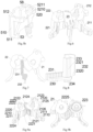
- the operating device includes an operating mechanism 1 and a contact system 2.
- the operating mechanism 1 is in driving connection with the contact system 2 so as to drive the contact system 2 to be closed or disconnected.
- the switching device further includes a wire-incoming terminal 31 and a wire-outgoing terminal 32.
- the contact system 2 is connected in series between the wire-incoming terminal 31 and the wire-outgoing terminal 32.
- the switching device is electrically connected to an external circuit (i.e., a circuit where the switching device is located) through the wire-incoming terminal 31 and the wire-outgoing terminal 32.
- the contact system 2 includes a contact mechanism.
- the contact mechanism includes a first contact structure 21 and a second contact structure 22 which are oppositely arranged side by side.
- a rotation direction of the first contact structure 21 keeps opposite to a rotation direction of the second contact structure 22.
- the first contact structure 21 and the second contact structure 22 rotate synchronously toward each other to be closed and rotate synchronously away from each other to be broken.
- a contact point of the first contact structure 21 and a contact point of the second contact structure 22 moves toward each other to be closed (the first contact point 2110 and the second contact point 2210 move close to each other to be closed) or move away from each other to be broken (the first contact point 2110 and the second contact point 2210 move away from each other to be broken).
- the first contact structure 21 includes a first support 212 arranged pivotally around a first center 21s and a first contact 211 arranged on the first support 212.
- the first contact 211 may also be referred to as a first moving contact.
- the first contact 211 rotates around the first center 21s under the driving of the first support 212. That is, the first support 212 bears the first contact 211 (the first moving contact) and drives the first contact 211 to rotate.
- the second contact structure 22 includes a second support 222 arranged pivotally around a second center 22s and a second contact 221 arranged on the second support 222.
- the second contact 221 may also be referred to as a second moving contact.
- the second contact 221 rotates around the second center 22s under the driving of the second support 222. That is, the second support 222 bears the second contact 221 (the second moving contact) and drives the second contact 221 to rotate.
- first contact 211 is inserted on the first support 212, and the first contact point 2110 is arranged at the other end of the first contact 211; and one end of the second contact 221 is inserted on the second support 222, and the second contact point 2210 is arranged at the other end of the second contact 221.
- the first support 212 and the second support 222 are arranged pivotally on the first supporting structure, respectively.
- the first supporting structure is realized by the switch housing h.
- the switch housing h includes a housing base and a housing cover (not shown) that are oppositely buckled together.
- the housing base includes a first support shaft column and a second support shaft column which are arranged on a bottom plate of the housing base.
- a first base shaft hole h21 and a second base shaft hole h22 which are matched with rotating shafts (i.e., the first support shaft 2124 and the second support shaft 2222) of the first support 212 and the second support 222 are respectively formed in the middle of the first support shaft column and the second support shaft column.
- the first contact structure 21 and the second contact structure 22 are arranged in a symmetrical pivoting manner, and the symmetrical pivoting refers to symmetry of the first contact structure 21 and the second contact structure 22 in both rotation center and rotation angle, so that the first contact structure 21 and the second contact structure 22 rotate within a limited space and have a larger opening distance, thereby saving an internal space of the switching device, improving the breaking performance, facilitating the design and layout and also improving the aesthetic property.
- the first contact structure 21 and the second contact structure 22 may also be asymmetrically arranged.
- the operating mechanism 1 is in driving connection with the first contact structure 21 and/or the second contact structure 22 to drive the first contact structure 21 and the second contact structure 22 to rotate synchronously toward each other or to rotate synchronously away from each other.
- a first implementation mode in which the operating mechanism 1 is in driving connection with the contact system 2 is as follows: the first contact structure 21 and the second contact structure 22 are in transmission fit and rotatably arranged in linkage (that is, one of the first contact structure 21 and the second contact structure 22 rotates, and the other one is directly driven by the former and rotates synchronously); the operating mechanism 1 is in driving connection with the first contact structure 21; the operating mechanism 1 drives the first contact structure 21 to rotate, and the first contact structure 21 drives the second contact structure 22 to rotate simultaneously, so as to realize the synchronous rotation toward each other or away from each other of the first contact structure 21 and the second contact structure 22.
- the first contact structure 21 and the second contact structure 22 are in transmission fit with each other.
- the symmetrical and synchronous pivoting of the first contact structure 21 and the second contact structure 22 is conducive to the design of a transmission structure between the first contact structure 21 and the second contact structure 22, achieves higher and more reliable transmission efficiency, and ensures the closing and breaking reliability of the first contact structure 21 and the second contact structure 22.
- the operating mechanism 1 may also be in driving connection with the second contact structure 22.
- the operating mechanism 1 drives the second contact structure 22 to rotate; the second contact structure 22 drives the first contact structure 21 to rotate simultaneously, so as to realize the synchronous rotation toward each other or away from each other of the first contact structure 21 and the second contact structure 22.
- one end of the first contact structure 21 and one end of the second contact structure 21 are arranged pivotally around the first center 21s and the second center 22s respectively, and the other ends thereof are closed or broken to close or break the contact system 2.
- a first embodiment of the contact system 2 is shown, wherein the operating mechanism 1 is in linkage with the first support 212 of the first contact structure 21, and the first support 212 is in linkage with the second support 222; the operating mechanism 1 drives the first support 212 to rotate, so as to drive the first contact 211 to rotate; and the first support 212 drives the second support 222 to rotate, so as to drive the second contact to rotate, so that the first contact 211 and the second contact 221 synchronously rotate toward each other or away from each other.
- the first support 212 includes a master gear 2121.
- the second support 222 includes a slave gear 2221.
- the master gear 2121 is meshed with the slave gear 2221 to realize the driving fit between the first contact structure 21 and the second contact structure 22.
- the first support and the second support realize synchronous rotation through gear meshing, and work more reliably and stably.
- an axis of the master gear 2121 coincides with the first center 21s
- an axis of the slave gear 2221 coincides with the second center 22s.
- the axis of the master gear 2121 may also not coincide with the first center 21s
- the axis of the slave gear 2221 may also not coincide with the second center 22s.
- the master gear 2121 and the slave gear 2221 are both sector-shaped gears.
- the first support 212 includes a first support main body 2120 arranged pivotally around the first center 21s.
- Gear teeth of the master gear 2121 are sequentially arranged on a circumferential side wall of the first support main body 2120 in a circumferential direction of the first support main body 2120. That is, the first support main body 2120 and the gear teeth arranged on the circumferential side wall of the first support main body 2120 form the master gear 2121.
- the second support 222 includes a second support main body 2220 arranged pivotally around the second center 22s. Gear teeth of the slave gear 2221 are sequentially arranged on a circumferential side wall of the second support main body 2220 in a circumferential direction of the second support main body 2220.
- the second support main body 2220 and the gear teeth arranged on the circumferential side wall of the second support main body 2220 form the slave gear 2221.
- the gear teeth of the master gear 2121 and the gear teeth of the slave gear 2221 are located between the first support main body 2120 and the second support main body 2220 and mesh with each other.
- the first contact structure 21 and the second contact structure 22 are arranged in a symmetrical and synchronous pivoting manner and are in transmission fit with each other, only one contact reset spring (i.e., the second reset spring 223 or the first reset spring) needs to be arranged, such that the first contact structure 21 may be quickly broken from the second contact structure 22, achieving a simple structure and reliable action.
- the second reset spring 223 or the first reset spring only one contact reset spring (i.e., the second reset spring 223 or the first reset spring) needs to be arranged, such that the first contact structure 21 may be quickly broken from the second contact structure 22, achieving a simple structure and reliable action.
- a specific connection mode of the operating mechanism 1 and the contact system 2 is as follows: the jump catch 13 and the lock catch 14 are arranged pivotally on the first support 212 respectively and are in snap fit with each other.
- the first support 212 is used as the rotating plate.
- Two ends of the main link rod 12 are hinged with the operating member 11 and the jump catch 13, respectively.
- the operating member 11 is driven by an external force to rotate and drives the jump catch 13, the lock catch 14 and the first support 212 to rotate as a whole around the first center 21s through the main link rod 12, such that the contact system 2 is closed or broken.
- the lock catch structure is driven by an external force (for example, an acting force exerted by the thermomagnetic tripping mechanism 5 to the lock catch structure, wherein a matching relationship between the thermomagnetic tripping mechanism 5 and the lock catch structure will be described in detail later) to rotate and release the snap fit between the lock catch structure and the jump catch 13 (that is, the snap fit between the lock catch 14 and the jump catch 13).
- an external force for example, an acting force exerted by the thermomagnetic tripping mechanism 5 to the lock catch structure, wherein a matching relationship between the thermomagnetic tripping mechanism 5 and the lock catch structure will be described in detail later
- the first support 212 further includes a jump catch limiting block 2128 arranged on one side of the jump catch shaft 2123.
- the jump catch limiting block 2128 is in limiting fit with the jump catch 13 to limit a range of the jump catch 13 to swing with respect to the first support main body 2120 of the first support 212.
- the thermal tripping structure directly drives the linkage rocker 15 to rotate through a thermal tripping transmission member 55 that is arranged pivotally, and the linkage rocker 15 drives the lock catch 14 to rotate, thereby releasing the snap fit between the lock catch 14 and the jump catch 13.
- the magnetic tripping structure directly drives the lock catch 14 to rotate through the magnetic tripping transmission member 54, thereby releasing the snap fit between the lock catch 14 and the jump catch 13.
- the lock catch structure, the thermal tripping transmission member 55 and the magnetic tripping transmission member 54 are distributed at three vertices of a triangle. Further, the lock catch 14 and the linkage rocker 15 are both arranged pivotally around the first center 21s.
- the magnetic tripping transmission member 54 is arranged pivotally around a third center for 54s.
- the thermal tripping transmission member 55 is arranged pivotally around a fourth center 55s. The first center 21s, the third center 54s and the fourth center 55s are distributed at three vertices of a triangle.
- the lock catch 14, the first support 212 and the linkage rocker 15 are sequentially stacked along the rotating shaft of the lock catch 14, and the lock catch 14 and the linkage rocker 15 are respectively located on both sides of the first support 212.
- the lock catch 14 includes a lock catch main body 140 and a lock catch second arm 142 arranged on the lock catch main body 140, and the lock catch 14 is arranged pivotally through the lock catch main body 140.
- the linkage rocker 15 includes a rocker mounting portion 150 and a rocker first arm 151 arranged on the rocker mounting portion 150.
- the linkage rocker 15 is arranged pivotally through the rocker mounting portion 150, and the lock catch second arm 142 is in driving connection with the rocker first arm 151.
- the lock catch second arm 142 includes a lock catch second arm connecting portion 1420 and a lock catch second arm driven portion 1421.
- the rocker first arm 151 is provided with a rocker first arm matching groove 1510, and the lock catch second arm driven portion 1421 is inserted in the rocker first arm matching groove 1510, so as to realize the synchronous rotation of the lock catch 14 and the linkage rocker 15. Further, an extension direction of the lock catch second arm driven portion 1421 is parallel to the direction of the rotating shaft of the lock catch 14.
- the linkage rocker 15 further includes a rocker second arm 152 connected to the rocker main body 150.
- the lock catch 14 also includes a lock catch first arm 141 connected to the lock catch main body 14.
- the rocker main body 150 of the linkage rocker 15 includes a rocker main body shaft hole 1500 formed in the middle, and the rocker main body 150 is rotatably sleeved onto a first support shaft column of the housing base through the rocker main body shaft hole 1500.
- an included angle between the lock catch first arm 141 and the lock catch second arm 142 is an obtuse angle
- an included angle between the rocker first arm 151 and the rocker second arm 152 is an obtuse angle.
- the lock catch first arm 141 and the rocker second arm 152, as well as the lock catch second arm 142 and the rocker first arm 151 are correspondingly arranged in the direction of the rotating shaft of the lock catch 14.
- the first contact structure 21 further includes a first contact spring 213.
- the first contact 211 is arranged rotatably with respect to the first support 212.
- the first contact spring 213 is arranged between the first contact 211 and the first support 212.
- the first contact spring 213 exerts a first acting force to the first contact 211.
- the first contact 211 rotates with respect to the first support 212 so that the first contact spring 213 stores energy, and the first acting force makes the first contact 211 press against the second contact 221, that is, the first contact spring 213 provides an overtravel force to the first contact 211 to ensure that the first contact 211 and the second contact 221 are reliably closed.
- the first contact 211, the first support 212 and the first contact spring 213 are assembled in the following manner:
- the first support 212 includes a first support main body 2120 and a first contact limiting block 2126;
- a first support cavity 21200 is formed in the middle of the first support main body 2120;
- a first contact insertion hole 21201 is formed in a side wall of the first support cavity 21200; one end of the first contact 211 is inserted into the first support cavity 21200 via the first contact insertion hole 21201;
- the first contact limiting block 2126 is arranged on an outer side wall of the first support main body 2120 and is located on one side of the first contact insertion hole 21201;
- the first contact spring 213 is a torsion spring arranged in the first support cavity 21200; one end of the torsion spring is in limiting fit with the inner side wall of the first support cavity 21200, and the other end of the torsion spring is in limiting fit with one end of the first contact 211 inserted in the first support cavity 21
- the above assembly manner is simple in structure and reliable in assembly, and guarantees the reliable action of the first contact structure 21.
- the first contact limiting block 2126 is also used for shielding a part of the first contact 211 which protrudes out of the first support 212 and is close to the first support 212, which is conducive to increasing an electrical clearance and creepage distance between the first contact structure 21 and the second contact structure 22 after breaking.
- the first support 212 further includes a first contact spring shaft 2127 arranged in the first support cavity 21200, and the first contact spring 213 is sleeved onto the first contact spring shaft 2127.
- the first contact spring 213 may alternatively be provided as a tension spring, and two ends of the tension spring are respectively hung to one end of the first contact 211 inserted into the first support cavity 21200 and to the first contact spring shaft 2127.
- an arrangement position of the first contact spring shaft 2127 needs to be adjusted accordingly.
- the lock catch shaft 2123, one first support shaft 2124 and the jump catch limiting block 2128 are arranged at an axial end of the first support main body 2120.
- the first support cavity 21200 is formed in an axial middle part of the first support main body 2120, and the other first support shaft 2124 is arranged at the other axial end of the first support main body 2120. Further, one side of the first support cavity 21200 facing the linkage rocker 15 is open.
- the second contact structure 22 further includes a second contact spring (not shown), the second contact 221 is rotatably arranged with respect to the second support 222, and the second contact spring is arranged between the second contact 221 and the second support 222; and the second contact spring exerts a second acting force to the second contact 221.
- the second acting force causes the second contact 221 to be in limiting fit with the second support 222 and remain relatively stationary.
- the second contact 221 rotates with respect to the second support 222 so that the second contact spring may release energy.
- the second acting force causes the second contact 221 to press against the first contact 211, that is, the second contact spring provides an overtravel force to the second contact 221 to ensure that the second contact 221 and the first contact 211 are reliably closed.
- the second contact limiting block 2224 is also used for shielding a portion of the second contact 221 which protrudes out of the second support 222 and is close to the second support 222, which is conducive to increasing an electrical clearance and creepage distance between the first contact structure 21 and the second contact structure 22 after breaking.
- the second contact 221, the second support 222 and the second contact spring are assembled in the following manner: the second support 222 includes a second support main body 2220 and a second contact limiting block 2224; a second support cavity is formed in the middle of the second support main body 2220; a side wall of the second support cavity is provided with a second contact insertion hole; one end of the second contact 221 is inserted into the second support cavity via the second contact insertion hole; the second contact limiting block 2224 is arranged on an outer side wall of the second support main body 2220 and is located on one side of the second contact insertion hole; the second contact spring is a torsion spring arranged in the second support cavity; one end of the torsion spring is in limiting fit with an inner side wall of the second support cavity, and the other end of the torsion spring is in limiting fit with one end of the second contact 221 inserted in the second support cavity such that the second contact props against the second contact limiting block 2224; and the second contact 221 is
- the second support 222 further includes second support shafts 222, and the two second support shafts 222 are respectively arranged at two axial ends of the second support main body 2220.
- the second contact spring may alternatively be provided as a tension spring, and two ends of the tension spring are respectively hung to one end of the second contact 221 inserted into the second support cavity and to the second contact spring shaft.
- an arrangement position of the second contact spring shaft needs to be adjusted accordingly.
- the separator 23 can elongate and shield an electric arc generated between the first contact structure 21 and the second contact structure 22 in the breaking process, and is conducive to improving the breaking performance and the current-carrying capacity of the contact system 2. Further, the separator 23 moves as a whole, and is driven to move in a first direction or a second direction, and the first direction and the second direction are opposite directions to each other, so that the separation portion 232 moves to or out of the position between the first contact point 2110 and the second contact point 2210.
- first contact point 2110 and the second contact point 2210 i.e., mutual contact areas of the first contact structure 21 and the second contact structure 22
- a baffle plate 23 is driven to move upward and move out of the position between the first contact point 2110 and the second contact point 2210.
- the baffle plate 23 is driven to move downward and move to the position between the first contact point 2110 and the second contact point 2210.
- the separator 23 completely separates the first contact 211 (in particular, a part of the first contact 211 which protrudes out of the first support 212) of the first contact structure 21 from the second contact 221 (in particular, a part of the second contact structure 221 which protrudes out of the second support 222) of the second contact structure 22. That is, the first contact 211 and the second contact 221 are, one with respect to the other, completely shielded by the separator 23 in a direction perpendicular to a moving direction of the separator 23.
- the separator 23 may also be rotatably arranged. When the first contact structure 21 and the second contact structure 22 are closed, the separator 23 is driven to swing, such that the separation 232 moves out of the position between the first contact point 2110 and the second contact point 2210; and when the first contact structure 21 is broken from the second contact structure 22, the separator 23 is driven to swing, such that the separation portion 232 moves to the position between the first contact point 2110 and the second contact point 2210.
- the separator 23 in the present embodiment is used for separating the first contact structure 21 and the second contact structure 22 which are arranged in a symmetrical and synchronous pivoting manner.
- the separator may also be used to separate the first contact structure 21 and the second contact structure 22 which are arranged synchronously but asymmetrically and are both in moving fit with each other.
- the separator 23 is driven by the first contact structure 21 to act, so that the separation portion 232 moves to or out of the position between the first contact point 2110 and the second contact point 2210.
- gear teeth of the separator driving gear 2122 are sequentially arranged on a circumferential side wall of the first support main body 2120 along a circumferential direction of the first support main body 2120 of the first support 2120. That is, the first support main body 2120 and the gear teeth of the separator driving gear 2122 arranged on the circumferential side wall of the first support main body 2120 form the separator driving gear 2122.
- the gear teeth of the separator driving gear 2122 and the gear teeth of the master gear 2121 are arranged side by side along an axial direction of the first support 212.
- the second support 222 includes a separator limiting table 2223.
- the separator limiting table 2223 and the separator driving gear 2122 are respectively located on both sides of the separator rack 231.
- the separator limiting table 2223 is in limiting fit with the separator rack 231, such that the separator rack 231 and the separator driving gear 2122 remain meshed.
- the separator rack 231 includes teeth arranged on its front and a rack limiting side surface arranged on its back.
- the separator limiting table 2223 abuts against and limits the rack limiting side surface, so that the separator rack 231 and the separator driving gear 2122 remain meshed.
- the separator limiting table 2223 is a sector-shaped table a circle center of which coincides with the second center 22s and includes a limiting arc surface, wherein the limiting arc surface is in line contact with the separator rack 231, thereby reducing a frictional force therebetween while ensuring a limiting effect.
- One ends of the separator rack 231 and the separator backplate 230 in the length direction of the separator rack 231 are respectively connected to the separation portion 232.
- the separator backplate 230 is conducive to enhance the strength of the separator rack 231.
- the separator 23 is formed into an L-shaped structure as a whole.
- the separation portion 231 is used as one edge of the L-shaped structure, and the separator rack 231 and the separator backplate 230 are used as another edge of the L-shaped structure.
- the separation portion 232 includes a separation plate 2320 and a reinforced connecting portion 2321.
- One ends of the separator rack 231 and the separator backplate 230 in the length direction of the separator rack 231 are respectively connected to the reinforced connecting portion 2321.
- the separator backplate 230 and the separator rack 231 are located on one side of the reinforced connecting portion 2321, and the separation plate 2320 is located on the other side of the reinforced connecting portion 2321.
- the thickness of the reinforced connecting portion 2321 is greater than the thickness of the separation plate 2320, thereby enhancing the connection strength of the separator rack 231, the separator backplate 230 and the separation portion 232.
- two ends of the reinforced connecting portion 2320 in a thickness direction protrude out from both sides of the separation plate 2320, respectively.
- the separator 23 further includes a separator first sliding rib 233 and a separator second sliding rib 234 which are respectively arranged at both ends of the separation portion 232.
- the separator first sliding rib 233 and the separator second sliding rib 234 are respectively used for sliding fit with a first guide groove h23 and a second guide groove (not shown) which are fixedly arranged, so as to confine a moving path of the separator 23 and ensure the reliable fit among the separator, the first contact structure 21 and the second contact structure 23.
- the first guide groove h23 and the second guide groove are respectively formed in the housing base and the housing cover of the switch housing h.
- the switching device of the present invention further includes a thermomagnetic tripping device.
- the thermomagnetic tripping device is used for driving the operating mechanism 1 to trip when an overload or short-circuit fault occurs in a circuit where the switching device is installed, so that the circuit where the switching device is located is broken by the contact system 2.
- the thermomagnetic tripping device includes a thermomagnetic tripping mechanism 5.
- the thermomagnetic tripping mechanism 5 includes a thermal tripping structure and a magnetic tripping structure.
- the thermal tripping structure is used for driving the operating mechanism 1 to trip and open when an overload fault occurs in the circuit where the circuit breaker is installed.
- the magnetic tripping structure is used for driving the operating mechanism 1 to trip and open when a short-circuit fault occurs in the circuit where the switching device is installed.
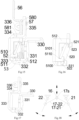
- the thermal tripping structure includes a bimetallic sheet 56, wherein one end of the bimetallic sheet 56 in a length direction is fixedly connected to the magnetic tripping structure.
- the magnetic tripping structure and the thermal tripping structure are arranged side by side.
- This layout mode is conducive to reducing a mounting space required by the thermomagnetic tripping mechanism 5, so that the thermomagnetic tripping mechanism 5 can be mounted within a narrow space.
- the thermal tripping structure and the magnetic tripping structure are of an integrated modular structure, facilitating transportation, installation and disassembly, and improves the positioning accuracy of various components of the thermomagnetic tripping mechanism, such that the thermomagnetic tripping mechanism will not change by the deformation of a housing used for mounting the thermomagnetic tripping mechanism, thereby ensuring the action performance of the thermomagnetic tripping mechanism.
- thermomagnetic tripping mechanism 5 As shown in FIGs. 1-2 , 4-5b and 15-17 , a first embodiment of the thermomagnetic tripping mechanism 5 is shown.
- the armature 52 is used as a magnetic tripping driving member, wherein one end of the armature is rotatably arranged and is an armature pivoting end (the armature pivoting end is used as the driving member mounting end), and the other end of the armature swings and is an armature driving end (the armature driving end is used as the driving member driving end).
- the armature 52 swings so as to be attracted with or separated from the yoke 51.
- a conductive plate matching section 333 of the current-carrying conductive plate 33 passes through the middle of the yoke 51 and is located between the yoke 51 and the armature 52.
- the current-carrying conductive plate 33 is also used as a conductive plate for serial connection of the contact system 2 and the wire-incoming terminal 31.
- the above-mentioned layout of the thermal tripping structure and the magnetic tripping structure of the first embodiment compared with the traditional mode in which the bimetallic assembly is placed between the yoke and the armature of the magnetic tripping structure, is conducive to reducing the size and specification of the yoke 51 and reducing the overall thickness (i.e., the thickness in a direction from the armature 52 to the yoke 51) of the thermomagnetic tripping mechanism 5.
- the magnetic tripping structure further includes an armature spring 53.
- the armature spring 53 is connected to the armature 52, and exerts an acting force to the armature 52, so that the armature 52 has a rotational tendency to be separated from the yoke 51.
- the acting force exerted on the armature 52 by the armature spring 53 needs to be overcome.
- the current-carrying conductive plate 33 further includes a conductive plate second intermediate section 332, wherein one end of the conductive plate second intermediate section 332 is connected to one end of the conductive plate matching section 333 away from a bimetallic assembly in a bending manner, one end of the armature spring 53 is connected to the armature driving end of the armature 52, and the other end of the armature spring 53 is connected to the conductive plate second intermediate section 332.
- the thermal tripping structure further includes a bimetallic bracket 58.
- the bimetallic bracket 58 includes a vertical bracket portion 580 and a horizontal bracket portion 581, wherein one end of the vertical bracket portion 580 is connected to the bimetallic sheet 56, and the other end of the vertical bracket portion 580 is connected to the horizontal bracket portion 581 in a bending manner.
- the current-carrying conductive plate 33 further includes a conductive plate third intermediate section 334 which is connected to the conductive plate matching section 333 in a bending manner. The conductive plate third intermediate section 334 is located between the magnetic tripping structure and the bimetallic bracket 58.
- the horizontal bracket portion 581 and the conductive plate third intermediate section 334 are laminated in parallel and connected fixedly, that is, the bimetallic sheet 56 is fixedly connected to the magnetic tripping structure through the bimetallic bracket 58.
- the bimetallic bracket 58 is of an L-shaped structure, and the vertical bracket portion 580 and the horizontal bracket portion 581 are respectively used as two side edges of the L-shaped structure.
- the current-carrying conductive plate 33 further includes a conductive plate bimetallic adjusting section 335 opposite to the vertical bracket portion 580.
- the conductive plate bimetallic adjusting section 335 is connected to the conductive plate third intermediate section 334 in a bending manner.
- the conductive plate bimetallic adjusting section 335 and the conductive plate matching section 333 are respectively bent toward both sides of the conductive plate third intermediate section 334.
- the conductive plate bimetallic adjusting section 335 is provided with an adjusting section screw hole.
- the thermal tripping structure further includes a bimetallic adjusting screw 57.
- the bimetallic adjusting screw 57 is in threaded fit with the adjusting section screw hole.
- One end of the bimetallic adjusting screw 57 is used for pressing against the vertical bracket portion 58 and adjusting the bimetallic sheet 56. Further, the conductive plate matching section 333, the conductive plate third intermediate section 334 and the conductive plate bimetallic adjusting section 335 are sequentially connected with one another in a right-angle bending manner.
- the bimetallic sheet 56 directly drives the linkage rocker 15 of the operating mechanism 1 to rotate through the thermal tripping transmission member 55, and the linkage rocker 15 drives the lock catch 14 to rotate and release the snap fit between the lock catch 14 and the jump catch 13.
- the thermal tripping transmission member 55 directly drives the lock catch 14 to rotate and release the snap fit with the jump catch 13. Further, a thermal tripping transmission member driving arm 552 of the thermal tripping transmission member 55 directly drives the lock catch second arm 142 of the lock latch 14.
- the thermal tripping transmission member 55 includes a thermal tripping transmission member mounting portion 550, a thermal tripping transmission member driven arm 551 and a thermal tripping transmission member driving arm 552.
- the thermal tripping transmission member 55 is arranged pivotally through the thermal tripping transmission member mounting portion 550.
- One end of the thermal tripping transmission member driven arm 551 is connected to the thermal tripping transmission member mounting portion 550, and the other end of the thermal tripping transmission member driven arm 551 is in driving fit with the bimetallic sheet 56.
- thermal tripping transmission member driving arm 552 One end of the thermal tripping transmission member driving arm 552 is connected to the thermal tripping transmission member mounting portion 550, and the other end of the thermal tripping transmission member driving arm 552 is in driving fit with the operating mechanism 1 to drive the lock catch 14 of the operating mechanism 1 to rotate and release the snap fit with the jump catch 13.
- the thermal tripping transmission member driven arm 551 and the thermal tripping transmission member driving arm 552 are distributed in an circumferential direction of the thermal tripping transmission member mounting portion 550. Further, a free end of the thermal tripping transmission member driving arm 552 is in driving fit with the linkage rocker 15 of the operating mechanism 1 to drive the linkage rocker 15 to rotate, and the linkage rocker 15 drives the lock catch 14 to rotate and release the snap fit with the jump catch 13. Further, an included angle between the thermal tripping transmission member driven arm 551 and the thermal tripping transmission member driving arm 552 is less than or equal to 90°.
- the thermal tripping transmission member mounting portion 550 includes a thermal tripping transmission member mounting hole 5500 formed in the middle thereof.
- the housing base is provided with a thermal tripping lever shaft h55.
- the thermal tripping transmission member mounting portion 550 is rotatably sleeved onto the thermal tripping lever shaft h55 through the thermal tripping transmission member mounting hole 5500.
- the yoke 51 includes a yoke main body 510, and a yoke supporting arm 511 and a yoke limiting arm 512 respectively arranged at both ends of the yoke main body 510.
- Two ends of the armature 52 are respectively the armature pivoting end and the armature driving end.
- the armature pivoting end is rotatably supported on the yoke supporting arm 511 and is in limiting fit with the yoke supporting arm 511 to limit the movement of the armature 52 along its rotation axis.
- the yoke main body 510 is of a U-shaped structure, and includes a yoke main body bottom plate 5100 and yoke main body side plates 5101. Two ends of the yoke main body bottom plate 5100 and the two yoke main body side plates 5101 are oppositely arranged at intervals, respectively.
- the conductive plate matching section 333 passes between the two yoke main body side plates 5101 and is opposite to and fixedly connected to the yoke main body bottom plate 5100. An edge of each yoke main body side plate 5101 facing the armature 52 is attracted with or separated from the armature 52.
- Each of the yoke main body side plates 5101 is provided with a yoke supporting arm 511 and a yoke limiting arm 512.
- the yoke supporting arms 511 on the two yoke main body side plates 5101 are arranged at intervals to face each other, and the yoke limiting arms 512 on the two yoke main body side plates 5101 are arranged at intervals to face each other.
- the armature driving end is rotatably supported on the two yoke limiting arms 512, and swings between the two yoke limiting arms 512. Further, both ends of the edge of each yoke main body side plate 5101 facing the armature 52 are provided with the yoke supporting arm 511 and the yoke limiting arm 512 separately.
- each yoke limiting arm 512 is provided with a magnetic yoke stop, and the two yoke stops protrude between the two yoke limiting arms 512.
- the two yoke stops are in limiting fit with the armature driving end, preventing the armature driving end from swinging out of a position between the two yoke limiting arms 512, so as to ensure that the armature 52 swings within a predetermined swing angle range with respect to the yoke 52.
- the armature 52 further includes an armature main plate 520.
- the armature main plate 520 is located between the armature supporting arm 511 and the armature limiting arm 512 and is matched with the yoke main body side plate 5101.
- One end of the armature main plate 520 is connected to the armature bottom feet 522, and the other end of the armature main plate 520 is connected to the armature limiting plate 5210.
- the magnetic tripping structure is a direct-acting electromagnetic trip and includes a coil winding 590, a coil skeleton 591, a yoke 592, an ejector rod 593, a fixed iron core and a moving iron core, wherein the coil winding 590 is sleeved onto the coil skeleton 591; the yoke 592 is connected to the coil skeleton 590 and arranged around the coil winding 590; the ejector rod 593 is used as a magnetic tripping driving member, and an axial direction of the ejector rod 593 is the same as a length direction of the bimetallic sheet 56; one end of the ejector rod 593 protrudes out of the coil skeleton 590 as the driving member driving end, and the other end of the ejector rod 593 is
- One end of the coil winding 590 is electrically connected to the wire-incoming conductive plate 36, and the other end of the coil winding 590 is electrically connected to the bimetallic bracket 58; and the wire-incoming conductive plate 36 is also matched with the wire-incoming terminal 31.
- the yoke 592 is of a U-shaped structure, which includes a yoke bottom plate and yoke side plates, wherein the two yoke side plates are respectively connected to both ends of the yoke bottom plate in a bending manner and are fixedly connected to both ends of the coil skeleton 591 respectively. Further, the yoke bottom plate and two terminals of the coil winding 590 are respectively located on two radial sides of the coil skeleton 590. Further, the two terminals of the coil winding 590 extend to both sides of two axial ends of the coil skeleton 590, respectively.
- the bimetallic bracket 58 is fixedly connected to the yoke 592, wherein one end of the bimetallic sheet 56 is fixedly and electrically connected to the bimetallic bracket 58, and the other end of the bimetallic sheet 56 is in transmission fit with the thermal tripping transmission member 55.
- the bimetallic bracket 58 is of an L-shaped structure as a whole, and includes a horizontal bracket portion 580 and a vertical bracket portion 581, wherein one end of the horizontal bracket portion 580 is fixedly connected to one end of the yoke 592, the other end of the horizontal bracket portion 580 is connected to one end of the vertical bracket portion 581 in a bending manner, and the other end of the vertical bracket portion 581 is fixedly and electrically connected to one end of the bimetallic sheet 56. Further, the horizontal bracket portion 580 is fixedly connected to the yoke side plate of the yoke 592 close to the thermal tripping structure.
- the magnetic tripping transmission member 54 includes a magnetic tripping transmission member first arm 541 and a magnetic tripping transmission member second arm 542, wherein one end of the magnetic tripping transmission member first arm 541 is in transmission connection with the ejector rod 593 of the magnetic tripping structure, and the other end of the magnetic tripping transmission member first arm 541 is connected to one end of the magnetic tripping transmission member second arm 542 in a bending manner; and the other end of the magnetic tripping transmission member second arm 542 is in transmission fit with the lock catch 14 of the operating mechanism 1, so as to drive the lock catch 14 to rotate and release the snap fit with the jump catch 13. Further, the magnetic tripping transmission member first arm 541 and the magnetic tripping transmission member second arm 542 are of a V-shaped structure as a whole.
- an included angle between the magnetic tripping transmission member first arm 541 and the magnetic tripping transmission member second arm 542 is an obtuse angle.
- the magnetic tripping transmission member 54 further includes a magnetic tripping transmission member mounting portion 540.
- the magnetic tripping transmission member 54 is arranged pivotally through the magnetic tripping transmission member mounting portion 540.
- the magnetic trip transmission member mounting portion 540 is arranged at one end of the magnetic tripping transmission member first arm 541 which is connected to the magnetic tripping transmission member second arm 542.
- the magnetic tripping transmission member 54 is of an integral structure, preferably formed by cutting and bending a metal plate.
- a matching process of the first support bearing portion 2125 of the first support 212 and the magnetic tripping transmission member 54 is as follows: as the magnetic tripping structure acts, the lock catch 14 is first driven to rotate and release the snap fit with the jump catch 13, and then drives the first support 212 through the first support bearing portion 2125 to rotate, so that the first support 212 rotates in a breaking direction.
- the armature 52 drives the magnetic tripping transmission member 541 to rotate through the magnetic tripping transmission member first arm 541, and the magnetic tripping transmission member 54 hits the lock catch second arm 142 of the lock catch 14 through the magnetic tripping transmission member second arm 542 such that the lock catch 14 rotates and disengage from the jump catch 13; and then the magnetic tripping transmission member second arm 542 hits the first support bearing portion 2125, so that the first support 212 rotates in the breaking direction to accelerate a breaking speed of the contact system 2.
- the lock catch 14 is hit by the magnetic tripping transmission member 54 to rotate, such that the lock catch 14 release the snap fit with the jump catch 13, and the lock catch 14 further rotates and hits the first support bearing portion 2125 of the first support 212, such that the first support bearing portion 2125 rotates in the breaking direction.
- the current-carrying conductive plate 33 further includes a conductive plate first intermediate section 331 and a conductive plate wiring section 330.
- the conductive plate wiring section 330, the conductive plate first intermediate section 331, the conductive plate second intermediate section 332, the conductive plate matching section 333, the conductive plate third intermediate section 334 and the conductive plate bimetallic adjusting section 335 are connected end to end in sequence.
- the conductive plate first intermediate section 331, the conductive plate second intermediate section 332, the conductive plate matching section 333 and the conductive plate third intermediate section 334 define a box-shaped structure.
- the conductive plate wiring section 330 is bent to one side away from the conductive plate matching section 333 with respect to the conductive plate first intermediate section 331.
- the conductive plate bimetallic adjusting section 335 is bent to one side away from the conductive plate second intermediate section 332 with respect to the conductive plate third intermediate section 334. Further, the conductive plate supporting arm 336 is connected to the conductive plate bimetallic adjusting section 335 in a bending manner and is located on the same side of the conductive plate bimetallic adjusting section 335 together with the conductive plate second intermediate section 334.
- the switching device further includes a wire-outgoing conductive plate 34, which is used for connecting the wire-outgoing terminal 32 in series with the contact system 2.
- the switching device further includes an arc-striking plate 35, wherein one end of the arc-striking plate 35 is electrically connected to the wire-outgoing conductive plate 34, and the other end of the arc-striking plate 35 extends to one side of the arc-extinguishing chamber 4.
- the switching device of the present invention is a circuit breaker, and adopts the following layout mode: the operating mechanism 1, the contact system 2, the wire-incoming terminal 31, the wire-outgoing terminal 32 and the arc-extinguishing chamber 4 are all arranged in a circuit breaker housing (i.e., the switch housing h); the operating member 11 of the operating mechanism 1, the contact system 2 and the arc-extinguishing chamber 4 are sequentially arranged in a height direction of the circuit breaker; the wire-incoming terminal 31 and the wire-outgoing terminal 32 are located at both ends of the circuit breaker in the length direction of the circuit breaker; the contact system 2 and the arc-extinguishing chamber 4 are located between the wire-incoming terminal 31 and the wire-outgoing terminal 32 in the length direction of circuit breaker, and the first contact structure 21 and the second contact structure 22 of the contact system 2 are arranged in symmetrical and synchronous rotation in the length direction of the circuit breaker; and the arc inlet of the arc
- the above-mentioned layout mode of the circuit breaker is reasonable and compact in layout and provides a larger assembly space for the arc-extinguishing chamber 4 of larger specification to be mounted, thereby being conducive to improving the arc-extinguishing performance and breaking performance of the circuit breaker.
- the first contact structure 21 and the second contact structure 22 are arranged in symmetrical and synchronous rotation, which not only can double the breaking speed of the contact system 2 but also doubles an opening distance, and thus is conducive to improving the breaking performance and current-carrying capacity of the short circuit. Specifically, as shown in FIGs. 1-2 and 19 , a left-right direction in FIGs.
- 1-2 and 19 i.e., a direction from the wire-incoming terminal 31 to the wire-outgoing terminal 32
- an up-down direction in FIGs. 1-2 i.e., the direction from the operating member 11 to the arc-extinguishing chamber 4
- an inside and outside direction of a paper surface in FIGs. 1-2 is the thickness direction of the circuit breaker.
- the rotation centers of the operating member 11, the first contact structure 21 and the second contact structure 22 are located at three vertices of a triangle.
- the above triangle is an acute triangle.
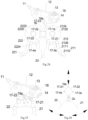
- the slider 16 is arranged in a linear sliding manner.
- the operating mechanism 1 may also be not connected to the slider 16, but is connected to any one of the first contact structure 21 and the second contact structure 22.
- the operating mechanism 1 drives the first contact structure 21 or the second contact structure 22 to rotate, and meanwhile the first contact structure 21 or the second contact structure 22 drives the second contact structure 22 or the first contact structure 21 to rotate through the cooperation of the first sub-link 17-21, the slider 16 and the second sub-link 17-22, so as to realize the synchronous rotation toward each other or away from each other of the first contact structure 21 and the second contact structure 22.
- the slider 16, the first sub-link 17-21 and the second sub-link 17-22 are all located between the first contact structure 21 and the second contact structure 22, and the first sub-link 17-21 and the second sub-link 17-22 are arranged in a V-shape.
- One end of the first contact structure 21 and one end of the second contact structure 22 are respectively arranged pivotally around the first center 21s and the second center 22s, and the other end of the first contact structure 21 and the other end of the second contact structure 22 are closed or broken (that is, the first contact point 2110 of the first contact structure 21 and the second contact point 2210 of the second contact structure 22 cooperate with each other to be closed or broken).
- first sub-link 17-21 is hinged with the slider 16, and the other end of the first sub-link 17-21 is hinged with the first contact structure 21.
- One end of the second sub-link 17-22 is hinged with the slider 16, and the other end of the second sub-link 17-22 is hinged with the second contact structure 22.
- one end of the first sub-link 17-21 is hinged with the slider 16, and the other end of the first sub-link 17-21 is hinged with the middle part of the first contact structure 21, wherein the middle part of the first contact structure 21 preferably refers to a part of the first contact structure 21 that is located between the first center 21s and the first contact point 2110 of the second contact structure 21.
- One end of the second sub-link 17-22 is hinged with the slider 16, and the other end of the second sub-link 17-22 is hinged with the middle part of the second contact structure 22, wherein the middle part of the second contact structure 22 preferably refers to a part of the second contact structure 22 that is located between the second center 22s and the second contact point 2210 of the second contact structure 22.
- the first sub-link 17-21 and the second sub-link 17-22 are symmetrically arranged, and are of structures symmetrical with each other.
- the first sub-link 17-21 and the second sub-link 17-22 are hinged with the slider 16 around a third center 17s, that is, one end of the first sub-link 17-21 and one end of the second sub-link 17-22 are coaxially and rotatably arranged on the slider 16.
- the first sub-link 17-21 is hinged with the first contact structure 21 around a third sub-center 17-3s.
- the second sub-link 17-22 is hinged with the second contact structure 22 around a fourth sub-center 17-4s.
- the third center 17s, the first center 21s and the second center 22s are respectively located at three vertices of an isosceles triangle.
- the first center 21s and the second center 22s are respectively located at vertices corresponding to two base angles of the isosceles triangle.
- the middle part of the first contact structure 21 and the middle part of the second contact structure 22 are respectively arranged pivotally around the first center 21s and the second center 22s, one end of the first contact structure 21 is hinged with the first sub-link 17-21, one end of the second contact structure 22 is hinged with the second sub-link 17-22, and the other end of the first contact structure 21 and the other end of the second contact structure 22 are closed or broken.
- the first sub-link 17-21 and the second sub-link 17-22 are hinged with the first support 212 and the second support 222, respectively. That is, one end of the first sub-link 17-21 is hinged with the slider 16, and the other end of the first sub-link 17-21 is hinged with the first support 212; and one end of the second sub-link 17-22 is hinged with the slider 16, and the other end of the second sub-link 17-22 is hinged with the second support 222, which is conducive to improving the insulativity.
- a first connection mode between the operating mechanism 1 and the contact system 2 in the second embodiment is as follows: the operating mechanism 1 includes an operating member 11, a main link rod 12, a jump catch 13 and a lock catch 14, wherein the jump catch 13 and the lock catch 14 are respectively arranged pivotally on the first contact structure 21 or the second contact structure 22 and snap fit with each other, and two ends of the main link rod 12 are hinged with the operating member 11 and the jump catch 13 respectively. Further, the jump catch 13 and the lock catch 14 are arranged pivotally on the first support 212, respectively.
- a working principle of the operating mechanism 1 is the same as the prior art, and will not be described herein.
- the jump catch 13 and the lock catch 14 are arranged pivotally on the second support 222, respectively.
- the slider 16 and the separator 23 are connected and move synchronously. Further, the slider 16 and the separator 23 are of an integrated structure, which is conducive to reducing the number of parts of the circuit breaker and improving the mounting efficiency and working stability.
- the slider 16 is slidably arranged on the circuit breaker housing.
- the first contact structure 21 and the second contact structure 22 are arranged pivotally on the circuit breaker housing (specifically, the first support 212 is arranged pivotally on the circuit breaker housing through its first support shaft 2124, and the second support 222 is arranged pivotally on the circuit breaker housing through its second support shaft 2222), respectively.
- a second connection mode of the operating mechanism 1 and the contact system 2 in the second embodiment is as follows: the operating mechanism 1 includes an operating member 11, a main link rod 12, a jump catch 13, a lock catch 14, a supporting member 18 and a supporting member link 17-23, wherein the operating member 11 and the supporting member 18 are arranged pivotally, respectively; the jump catch 13 and the lock catch 14 are arranged pivotally on the supporting member 18, respectively; two ends of the main link rod 12 are hinged with the operating member 11 and the jump catch 13, respectively; and two ends of the supporting member link 17-23 are hinged with the supporting member 18 and the slider 16, respectively. Further, the supporting member link 17-23 is hinged with the slider 16 around a link-slider center.
- first sub-link 17-21 is hinged with the slider 16 around a first sub-center 17-1s
- the second sub-link 17-22 is hinged with the slider 16 around a second sub-center 17-2s
- the first sub-center 17-1s and the second sub-center 17-2s are arranged at intervals in parallel.
- the link-slider center, the first sub-center 17-1s and the second sub-center 17-2s are located at three vertices of a triangle.
- the above triangle is an isosceles triangle
- the first sub-center 17-1s and the second sub-center 17-2s are located at vertices corresponding to two base angles of the isosceles triangle, respectively.
- the first sub-link 17-21 and the second sub-link 17-22 are hinged with the slider 16 around the same center.
- a third connection mode between the operating mechanism 1 and the contact system 2 in the second embodiment is as follows: the third connection mode is different from the second connection mode in a connection structure of the operating mechanism 1 and the contact system 2, specifically: one end of the supporting member link 17-23 is hinged with the supporting member 18, and the other end of the supporting member link 17-23 is hinged with the first contact structure 21 or the second contact structure 22.
- the supporting member link 17-23 is hinged with the first support 212 of the first contact structure 21.
- the supporting member link 17-23 can be changed to be hinged with the second support 222 of the second contact structure 22.
- FIGs. 25-26 a third embodiment of the contact system 2 is shown.
- the middle part of the first contact structure 21 and the middle part of the second contact structure 22 are both arranged pivotally around a contact mechanism center 2s, that is, arranged coaxially and rotatably.
- One end of the first sub-link 17-21 is hinged with the slider 16, and the other end of the first sub-link 17-21 is hinged with one end of the first contact structure 21 around a third sub-center 17-3s.
- One end of the second sub-link 17-22 is hinged with the slider 16, and the other end of the second sub-link 17-22 is hinged with one end of the second contact structure 22 around a fourth sub-center 17-4s.
- the slider 16, the third sub-center 17-3s, the contact mechanism center 2s and the fourth sub-center 17-4s are located at four vertices of a quadrilateral, respectively.
- the operating mechanism 1 includes an operating member 11, a main link rod 12, a jump catch 13, a lock catch 14, a supporting member 18 and a supporting member link 17-23, wherein the operating member 11 and the supporting member 18 are arranged pivotally, respectively; the jump catch 13 and the lock catch 14 are arranged pivotally on the supporting member 18, respectively; two ends of the main link rod 12 are hinged with the operating member 11 and the jump catch 13, respectively; and the supporting member 18 is in transmission connection with the slider 16. Further, the first sub-link 17-21 and the second sub-link 17-22 are hinged with the supporting member 18 around a fifth center 19s through a link hinging shaft.
- first sub-link 17-21 and the second sub-link 17-22 are both hinged with the supporting member 18 through the link hinging shaft, and an axis of the link hinging shaft coincides with the fifth center 19s; and the link hinging shaft is used as the slider 16.
Landscapes
- Breakers (AREA)
Applications Claiming Priority (3)
| Application Number | Priority Date | Filing Date | Title |
|---|---|---|---|
| CN202310135654.4A CN118522616A (zh) | 2023-02-18 | 2023-02-18 | 断路器 |
| CN202310135688.3A CN118522611A (zh) | 2023-02-18 | 2023-02-18 | 断路器 |
| PCT/CN2023/125270 WO2024169215A1 (fr) | 2023-02-18 | 2023-10-18 | Disjoncteur |
Publications (1)
| Publication Number | Publication Date |
|---|---|
| EP4539086A1 true EP4539086A1 (fr) | 2025-04-16 |
Family
ID=92422171
Family Applications (1)
| Application Number | Title | Priority Date | Filing Date |
|---|---|---|---|
| EP23922332.4A Pending EP4539086A1 (fr) | 2023-02-18 | 2023-10-18 | Disjoncteur |
Country Status (2)
| Country | Link |
|---|---|
| EP (1) | EP4539086A1 (fr) |
| WO (1) | WO2024169215A1 (fr) |
Families Citing this family (1)
| Publication number | Priority date | Publication date | Assignee | Title |
|---|---|---|---|---|
| CN120149105B (zh) * | 2025-05-13 | 2025-08-12 | 浙江艾顿电气有限公司 | 一种能快速接线的一二次融合智能柱上断路器 |
Family Cites Families (7)
| Publication number | Priority date | Publication date | Assignee | Title |
|---|---|---|---|---|
| JP6474976B2 (ja) * | 2014-08-14 | 2019-02-27 | 富士電機株式会社 | 回路遮断器 |
| CN107146745B (zh) * | 2016-03-01 | 2020-02-18 | 浙江正泰电器股份有限公司 | 电子式漏电断路器 |
| CN107863281A (zh) * | 2017-12-07 | 2018-03-30 | 厦门安达兴电气集团有限公司 | 一种转动式联动双动触头机构及开关断路器 |
| CN110416035B (zh) * | 2019-08-26 | 2024-08-09 | 厦门安达兴电气集团有限公司 | 一种交直流通用型塑壳断路器 |
| CN112992620B (zh) * | 2019-12-14 | 2025-07-01 | 浙江正泰电器股份有限公司 | 断路器的操作机构 |
| CN114068262B (zh) * | 2020-08-03 | 2025-01-28 | 天津首瑞智能电气有限公司 | 一种低压断路器 |
| CN114914131B (zh) * | 2022-05-31 | 2025-11-21 | 上海电器科学研究所(集团)有限公司 | 断路器 |
-
2023
- 2023-10-18 EP EP23922332.4A patent/EP4539086A1/fr active Pending
- 2023-10-18 WO PCT/CN2023/125270 patent/WO2024169215A1/fr not_active Ceased
Also Published As
| Publication number | Publication date |
|---|---|
| WO2024169215A1 (fr) | 2024-08-22 |
Similar Documents
| Publication | Publication Date | Title |
|---|---|---|
| US12431312B2 (en) | Operating mechanism of circuit breaker | |
| US7800007B2 (en) | Circuit breaker subassembly apparatus | |
| KR920006061B1 (ko) | 회로차단기의 솔레노이드 가동형 작동기구 | |
| US12308192B2 (en) | Quick tripping device and circuit breaker | |
| JP2011151023A (ja) | 限流型配線用遮断器の可動接触子アセンブリ | |
| US4342974A (en) | Multipolar type circuit breaker | |
| US20230377825A1 (en) | Operating mechanism of circuit breaker, and circuit breaker | |
| EP4539086A1 (fr) | Disjoncteur | |
| CN217061989U (zh) | 一种断路器 | |
| CA1268199A (fr) | Coupe-circuit a boitier moule | |
| EP4318537A1 (fr) | Disjoncteur | |
| CN109036985B (zh) | 断路器 | |
| CN117877934A (zh) | 断路器 | |
| CN118522616A (zh) | 断路器 | |
| CN219738890U (zh) | 热磁脱扣装置及断路器 | |
| CN220172042U (zh) | 热磁脱扣机构及断路器 | |
| CN223743580U (zh) | 静触头结构 | |
| CN223513887U (zh) | 操作装置 | |
| CN118522612A (zh) | 接触系统及断路器 | |
| CN108878226B (zh) | 断路器 | |
| CN116153730A (zh) | 断路器 | |
| CN118522606A (zh) | 热磁脱扣装置及断路器 | |
| CN116153724A (zh) | 断路器 | |
| CN220774251U (zh) | 操作机构及断路器 | |
| CN219106035U (zh) | 一种多极断路器 |
Legal Events
| Date | Code | Title | Description |
|---|---|---|---|
| STAA | Information on the status of an ep patent application or granted ep patent |
Free format text: STATUS: THE INTERNATIONAL PUBLICATION HAS BEEN MADE |
|
| PUAI | Public reference made under article 153(3) epc to a published international application that has entered the european phase |
Free format text: ORIGINAL CODE: 0009012 |
|
| STAA | Information on the status of an ep patent application or granted ep patent |
Free format text: STATUS: REQUEST FOR EXAMINATION WAS MADE |
|
| 17P | Request for examination filed |
Effective date: 20250110 |
|
| AK | Designated contracting states |
Kind code of ref document: A1 Designated state(s): AL AT BE BG CH CY CZ DE DK EE ES FI FR GB GR HR HU IE IS IT LI LT LU LV MC ME MK MT NL NO PL PT RO RS SE SI SK SM TR |