EP4539183A1 - Fabrication d'éléments de batterie au moyen d'extensions de collecteur de courant - Google Patents
Fabrication d'éléments de batterie au moyen d'extensions de collecteur de courant Download PDFInfo
- Publication number
- EP4539183A1 EP4539183A1 EP23203626.9A EP23203626A EP4539183A1 EP 4539183 A1 EP4539183 A1 EP 4539183A1 EP 23203626 A EP23203626 A EP 23203626A EP 4539183 A1 EP4539183 A1 EP 4539183A1
- Authority
- EP
- European Patent Office
- Prior art keywords
- conductors
- extension
- anode
- cathode
- arrester
- Prior art date
- Legal status (The legal status is an assumption and is not a legal conclusion. Google has not performed a legal analysis and makes no representation as to the accuracy of the status listed.)
- Pending
Links
Images


Classifications
-
- H—ELECTRICITY
- H01—ELECTRIC ELEMENTS
- H01M—PROCESSES OR MEANS, e.g. BATTERIES, FOR THE DIRECT CONVERSION OF CHEMICAL ENERGY INTO ELECTRICAL ENERGY
- H01M50/00—Constructional details or processes of manufacture of the non-active parts of electrochemical cells other than fuel cells, e.g. hybrid cells
- H01M50/50—Current conducting connections for cells or batteries
- H01M50/531—Electrode connections inside a battery casing
- H01M50/54—Connection of several leads or tabs of plate-like electrode stacks, e.g. electrode pole straps or bridges
-
- H—ELECTRICITY
- H01—ELECTRIC ELEMENTS
- H01M—PROCESSES OR MEANS, e.g. BATTERIES, FOR THE DIRECT CONVERSION OF CHEMICAL ENERGY INTO ELECTRICAL ENERGY
- H01M10/00—Secondary cells; Manufacture thereof
- H01M10/05—Accumulators with non-aqueous electrolyte
- H01M10/052—Li-accumulators
-
- H—ELECTRICITY
- H01—ELECTRIC ELEMENTS
- H01M—PROCESSES OR MEANS, e.g. BATTERIES, FOR THE DIRECT CONVERSION OF CHEMICAL ENERGY INTO ELECTRICAL ENERGY
- H01M50/00—Constructional details or processes of manufacture of the non-active parts of electrochemical cells other than fuel cells, e.g. hybrid cells
- H01M50/50—Current conducting connections for cells or batteries
- H01M50/531—Electrode connections inside a battery casing
- H01M50/538—Connection of several leads or tabs of wound or folded electrode stacks
-
- H—ELECTRICITY
- H01—ELECTRIC ELEMENTS
- H01M—PROCESSES OR MEANS, e.g. BATTERIES, FOR THE DIRECT CONVERSION OF CHEMICAL ENERGY INTO ELECTRICAL ENERGY
- H01M50/00—Constructional details or processes of manufacture of the non-active parts of electrochemical cells other than fuel cells, e.g. hybrid cells
- H01M50/50—Current conducting connections for cells or batteries
- H01M50/543—Terminals
- H01M50/545—Terminals formed by the casing of the cells
-
- H—ELECTRICITY
- H01—ELECTRIC ELEMENTS
- H01M—PROCESSES OR MEANS, e.g. BATTERIES, FOR THE DIRECT CONVERSION OF CHEMICAL ENERGY INTO ELECTRICAL ENERGY
- H01M50/00—Constructional details or processes of manufacture of the non-active parts of electrochemical cells other than fuel cells, e.g. hybrid cells
- H01M50/50—Current conducting connections for cells or batteries
- H01M50/543—Terminals
- H01M50/547—Terminals characterised by the disposition of the terminals on the cells
- H01M50/548—Terminals characterised by the disposition of the terminals on the cells on opposite sides of the cell
-
- H—ELECTRICITY
- H01—ELECTRIC ELEMENTS
- H01M—PROCESSES OR MEANS, e.g. BATTERIES, FOR THE DIRECT CONVERSION OF CHEMICAL ENERGY INTO ELECTRICAL ENERGY
- H01M50/00—Constructional details or processes of manufacture of the non-active parts of electrochemical cells other than fuel cells, e.g. hybrid cells
- H01M50/50—Current conducting connections for cells or batteries
- H01M50/543—Terminals
- H01M50/552—Terminals characterised by their shape
- H01M50/553—Terminals adapted for prismatic, pouch or rectangular cells
-
- H—ELECTRICITY
- H01—ELECTRIC ELEMENTS
- H01M—PROCESSES OR MEANS, e.g. BATTERIES, FOR THE DIRECT CONVERSION OF CHEMICAL ENERGY INTO ELECTRICAL ENERGY
- H01M50/00—Constructional details or processes of manufacture of the non-active parts of electrochemical cells other than fuel cells, e.g. hybrid cells
- H01M50/50—Current conducting connections for cells or batteries
- H01M50/543—Terminals
- H01M50/564—Terminals characterised by their manufacturing process
- H01M50/566—Terminals characterised by their manufacturing process by welding, soldering or brazing
-
- H—ELECTRICITY
- H01—ELECTRIC ELEMENTS
- H01M—PROCESSES OR MEANS, e.g. BATTERIES, FOR THE DIRECT CONVERSION OF CHEMICAL ENERGY INTO ELECTRICAL ENERGY
- H01M50/00—Constructional details or processes of manufacture of the non-active parts of electrochemical cells other than fuel cells, e.g. hybrid cells
- H01M50/50—Current conducting connections for cells or batteries
- H01M50/531—Electrode connections inside a battery casing
- H01M50/536—Electrode connections inside a battery casing characterised by the method of fixing the leads to the electrodes, e.g. by welding
-
- H—ELECTRICITY
- H01—ELECTRIC ELEMENTS
- H01M—PROCESSES OR MEANS, e.g. BATTERIES, FOR THE DIRECT CONVERSION OF CHEMICAL ENERGY INTO ELECTRICAL ENERGY
- H01M50/00—Constructional details or processes of manufacture of the non-active parts of electrochemical cells other than fuel cells, e.g. hybrid cells
- H01M50/60—Arrangements or processes for filling or topping-up with liquids; Arrangements or processes for draining liquids from casings
- H01M50/609—Arrangements or processes for filling with liquid, e.g. electrolytes
- H01M50/627—Filling ports
-
- Y—GENERAL TAGGING OF NEW TECHNOLOGICAL DEVELOPMENTS; GENERAL TAGGING OF CROSS-SECTIONAL TECHNOLOGIES SPANNING OVER SEVERAL SECTIONS OF THE IPC; TECHNICAL SUBJECTS COVERED BY FORMER USPC CROSS-REFERENCE ART COLLECTIONS [XRACs] AND DIGESTS
- Y02—TECHNOLOGIES OR APPLICATIONS FOR MITIGATION OR ADAPTATION AGAINST CLIMATE CHANGE
- Y02E—REDUCTION OF GREENHOUSE GAS [GHG] EMISSIONS, RELATED TO ENERGY GENERATION, TRANSMISSION OR DISTRIBUTION
- Y02E60/00—Enabling technologies; Technologies with a potential or indirect contribution to GHG emissions mitigation
- Y02E60/10—Energy storage using batteries
-
- Y—GENERAL TAGGING OF NEW TECHNOLOGICAL DEVELOPMENTS; GENERAL TAGGING OF CROSS-SECTIONAL TECHNOLOGIES SPANNING OVER SEVERAL SECTIONS OF THE IPC; TECHNICAL SUBJECTS COVERED BY FORMER USPC CROSS-REFERENCE ART COLLECTIONS [XRACs] AND DIGESTS
- Y02—TECHNOLOGIES OR APPLICATIONS FOR MITIGATION OR ADAPTATION AGAINST CLIMATE CHANGE
- Y02P—CLIMATE CHANGE MITIGATION TECHNOLOGIES IN THE PRODUCTION OR PROCESSING OF GOODS
- Y02P70/00—Climate change mitigation technologies in the production process for final industrial or consumer products
- Y02P70/50—Manufacturing or production processes characterised by the final manufactured product
Definitions
- the invention relates to a method for producing a battery cell equipped with at least two battery terminals arranged on opposite sides, wherein at least one electrode stack comprising a plurality of anode foils and cathode foils separated from one another by separator foils is arranged in a cell housing. Furthermore, the invention relates to a battery cell.
- hard-case cells are also known.
- Such battery cells have a rigid metallic housing and can be geometrically designed in a prismatic or round cell shape.
- the respective battery poles are positioned on the outside of the battery cell at the so-called terminals in a raised form to enable simplified electrical connection.
- the battery poles are usually integrated into a cell cover of the battery cell, which closes off an internal volume of the cell housing.
- the cell lid of the battery cell is usually made of a metal, such as aluminum, stainless steel, or nickel-plated steel.
- Battery terminals are insulated from the cell lid and connected to collectors.
- the battery terminals form an external electrical connection and are electrically connected to the collectors facing the interior volume of the cell housing.
- Electrode packs consisting of alternating layers of anodes, cathodes, and separators are arranged in the interior volume of the cell housing in electrochemical storage devices, such as lithium-ion batteries.
- electrochemical storage devices such as lithium-ion batteries.
- Such anode foils and cathode foils can be formed by winding or stacking and stored in the interior volume of the cell housing for the be positioned for final use by the customer.
- the respective anode foils and cathode foils must be connected to the battery terminals during battery cell production.
- anode conductors and cathode conductors serve as connecting lines between the battery terminals and the anode foils or cathode foils.
- the uncoated ends of the copper carrier foils of the anode foils and the aluminum carrier foils of the cathode foils, which protrude from the electrode package, are regularly welded to the two collectors.
- the anode conductors and cathode conductors must be made extra long. This extra length results in the use of electrodes with wide uncoated areas and in increased material requirements and waste.
- the electrodes are typically manufactured as a continuous strip. Active coatings on the carrier foils are compressed between pairs of rollers in a calender, and the anode foils or cathode foils are then punched out. Due to the required excess length, wide, uncoated areas of the carrier foils are provided, which can be particularly susceptible to warping during calendering.
- the present invention therefore aims to provide a method for manufacturing a battery cell in which material waste is reduced and the connection of arresters to collectors is simplified. This object is achieved by the features specified in claim 1. Further advantageous embodiments of the invention are part of the subclaims.
- a method for producing a battery cell which is equipped with at least two battery poles arranged on opposite sides.
- the battery poles can point or be oriented in two opposite directions.
- At least one electrode package is provided with a plurality of anode foils and cathode foils separated from each other by separator foils.
- the at least one electrode package can be configured in a folded or stacked form. This means that the anode foils, cathode foils, and separator foils can be cut to size, stacked on top of each other, or provided in the form of long, wound strips.
- the anode foils have anode conductors at their ends, and the cathode foils have cathode conductors at their ends.
- the anode conductors and cathode conductors can protrude from the edges of the cut or wound anode foils and cathode foils.
- the anode conductors of the anode foils are bundled or aligned on a first side of the electrode stack, and the cathode conductors of the cathode foils are bundled or aligned on a second side.
- the bundled anode conductors and/or cathode conductors are electrically connected, at least in some areas, to at least one conductor extension.
- only the anode conductors, only the cathode conductors, or the cathode conductors and the anode conductors can be extended by one or more conductor extensions.
- the anode conductors or the cathode conductors can be provided as so-called flag packs and, if necessary, can be flexibly extended with the conductor extension or busbar, which is welded to the edges of the anode conductors or cathode conductors of the electrode pack and forms the connection to the collector of the first and/or second battery pole.
- This measure can reduce the waste of the carrier film material of the anode foils and/or cathode foils to form sufficiently long anode conductors and/or cathode conductors. This can also improve the manufacturability of the anode foils and the cathode foils, since the anode conductor and/or cathode conductor to be formed can be designed short in the form of an uncoated carrier foil material in order to To minimize material distortion during the production of the anode foils and/or cathode foils.
- the at least one electrode stack equipped with at least one conductor extension, is inserted into a cell housing. Depending on the design, this step can be performed after connecting the first battery terminal or after connecting the second battery terminal.
- the anode conductors are electrically connected directly or indirectly via the at least one conductor extension to a collector of a first battery pole and the cathode conductors are electrically connected directly or indirectly via the at least one conductor extension to a collector of a second battery pole.
- the cell housing is closed by the first battery terminal and the second battery terminal.
- the cell housing can be open on two opposite sides to form a receiving space for the at least one electrode pack.
- the two open opposite sides or openings of the cell housing can be closed by the battery terminals after the insertion of the at least one electrode pack.
- a first battery terminal can first be connected to the anode conductor via the corresponding collector and folded over, then the electrode package with the first battery terminal can be pushed into the cell housing, with the first battery terminal closing a first opening in the cell housing.
- the second battery terminal can be connected directly or indirectly by means of a The arrester extension can be connected to the second battery terminal. Folding the second battery terminal closes a second opening in the cell housing.
- the at least one electrode stack can be pushed into the cell housing before or after connecting at least one arrester extension and then electrically coupled to both battery terminals simultaneously or sequentially. After the battery terminals are subsequently folded over, the cell housing can be closed.
- connection to the collector is made indirectly via the arrester extension when a arrester extension is connected to the anode arresters or cathode arresters.
- the connection to the corresponding collector can be made directly.
- At least one arrester extension can be used on at least one side of the electrode stack.
- the electrolyte solution for the battery cell can be added before or after the cell housing is closed.
- the cell housing can be closed in a fluid-tight manner.
- the battery terminals can be designed as cell lids or inserted into cell lids that seal the openings in the cell housing.
- the battery terminals or cell lids can be pressed into the cell housing and/or welded to the cell housing in order to make the receiving space of the cell housing fluid-tight.
- a filling opening can be provided in the cell housing, in at least one cell lid, and/or on at least one battery terminal for filling the cell housing with electrolyte.
- a battery cell which has at least one electrode package with a plurality of anode foils and cathode foils.
- the anode foils and cathode foils are separated from each other by separator foils. separated.
- the anode foils are provided with anode conductors on a first side and the cathode foils are provided with cathode conductors on a second side, which can be designed at least in some regions as stripped or uncoated sections of a carrier foil.
- the entire electrode package is arranged in a cell housing.
- the anode conductors are electrically connected directly or indirectly via a conductor extension to a collector of a first battery pole and/or the cathode conductors are electrically connected directly or indirectly via a conductor extension to a collector of a second battery pole.
- the first battery pole and the second battery pole are designed to close the cell housing at the ends.
- the battery cell may have a liquid electrolyte solution with which a receiving space of the cell housing is filled.
- the battery terminals form an electrical connection to the anode foils and cathode foils of the electrode pack to enable charging and discharging of the battery cell.
- At least one arrester extension made of a solid material or of a plurality of material layers that are at least partially interconnected or unconnected is provided to extend the anode arresters and/or cathode arresters.
- the arrester extension can be configured, for example, in the form of a busbar or a current-conducting foil.
- the arrester extension can be made of a metal or a metal alloy, such as copper or aluminum.
- the arrester extension can be provided with electrical insulation or coating, at least in certain areas, to prevent electrically conductive contact with battery terminals or the cell casing.
- the electrical insulation can be in the form of a paint or coating, or a flexible or shrinkable sheath.
- the arrester extension can advantageously be made of the same material as the arresters.
- the material can be copper for connecting anode arresters and aluminum for connecting cathode arresters.
- the at least one arrester extension can also have a conductor cross-section for conducting an electrical current that essentially corresponds to a conductor cross-section of the correspondingly connected arrester.
- the conductor cross-section of the arrester extension can be adjusted by adjusting the material thickness and the width of the arrester extension. This allows a constant specific electrical resistance to be set, which does not change between the collector and the electrode stack.
- a solid arrester extension can be made of a soft or bendable solid material.
- a arrester extension for an anode arrester extension can be made of copper material in a soft-annealed, non-work-hardened condition, allowing this arrester extension to be bent with very little force.
- the at least one arrester extension can be designed to be particularly flexible, at least in certain areas, if it is formed in the area of at least one bending point by several material layers that are not connected to each other, at least in the area of the bending point.
- the arrester extension can be made of laminated material with individual thin material foils. The arrester extension can therefore be folded with less force and on a tighter radius, thus saving installation space.
- this can be partially, especially in the area of bending points, or completely made of individual Metal foil layers can be combined to create targeted local bending points.
- Such bending points can enable reproducible folding of the arrester extension and the arresters.
- Areas of the arrester extension can be provided that have mechanically interconnected material layers or metal foil layers to define areas that do not require folding.
- the anode conductors and/or the cathode conductors are bundled centered or off-centered along a width direction of the battery cell.
- This measure allows the conductors to be optimally prepared for folding during further assembly of the battery cell. For example, based on the position of the bundling, the required bending radii when folding the conductors with the conductor extension can be limited or adjusted.
- Off-centered or edge-side bundling of the conductors can enable the entire width of the cell housing to be utilized for further bending or folding after a 90° bend. This can increase design freedom and provide the option of compensating for length variations of the conductors and conductor extensions, for example due to thermal or mechanical reasons.
- arresters can be simplified if the bundled anode arresters and/or cathode arresters are combined into a stack and fixed in a bundled form by connecting them to the at least one arrester extension and/or by introducing at least one connecting seam.
- the arresters can be combined, for example, by means of a material bond, clamping, or form-fitting. Combining the arresters can create an electrically conductive connection between the individual arresters or Produce carrier films or mechanically couple them together in an at least partially insulated form.
- the electrically conductive connection of the arresters to the collectors can be made outside the cell housing to ensure optimal tool access, e.g., for introducing a laser beam and a hold-down device during laser welding.
- tool access can be provided for a sonotrode and a corresponding anvil to realize ultrasonic welding of the arresters to the collector and/or the arrester extensions.
- the arresters Since the combined arresters (with or without an arrester extension) are initially parallel to the base of the electrode stack, and the collectors in the finished battery cell are generally aligned perpendicular to this for space reasons, the arresters must be folded during battery cell assembly. This may require an excess length of the anode arresters, at least in some areas, to allow tool access. The longer arresters can be arranged in a loop or folded during assembly. Such excess length can be provided particularly advantageously by at least one arrester extension, which can achieve optimal tool access even without an excessively long carrier foil layer.
- the tool access for connecting collectors to the arresters can be realized in a particularly versatile manner if the bundled anode arresters and/or cathode arresters are electrically connected, at least in some areas, to at least one foil-shaped or plate-shaped or pre-bent arrester extension.
- the at least one pre-bent arrester extension is arranged in the form of a bow or S-shaped or U-shaped in front of the The conductor extension is bent or folded for electrically conductive connection to the anode and/or cathode conductors.
- This measure allows the conductor extension to be bent in advance and, when connected to the anode and/or cathode conductors, bent flat, at least in some areas, for example, using a hold-down device. This bending is advantageously elastic.
- the at least one pre-bent conductor extension is elastically deformed flat, at least in part, to form an electrical connection to a collector.
- the conductor extension can be elastically deformed flat by a hold-down device. After connecting the conductor extension to the anode conductors and/or cathode conductors, the hold-down device can be released or removed, allowing the conductor extension to return to its pre-bent shape. This minimizes the force required to bend or fold the conductors and/or the conductor extension, thus also reducing the risk of damage to the electrode stack during battery cell assembly.
- At least two adjacent electrode packs are provided, wherein the bundled anode conductors and/or cathode conductors of a first electrode pack and a second electrode pack are electrically conductively connected, at least in some areas, to at least one conductor extension. This measure allows the conductors of both electrode packs to be coupled to a conductor extension via common connecting seams.
- the anode conductors of the first electrode stack are offset from the anode conductors of the second electrode stack along at least one spatial direction or are connected to the conductor extension in an overlapping manner. This allows the thickness of the conductors to be welded and the arrester extension, enabling more reliable welding.
- the cathode conductors of the first electrode stack are offset from the cathode conductors of the second electrode stack along at least one spatial direction or are connected to the conductor extension in an overlapping manner.
- This measure allows for further flexibility with regard to the connection to the conductor extension.
- this also allows shaped conductors of the different electrode stacks to form an overlap or offset with respect to one another, which can be advantageously used for introducing multiple connecting seams to create an electrically conductive connection between the conductors and the conductor extension.
- the arrester extension can be connected particularly robustly to at least one arrester by welding or soldering if one arrester extension for anode arresters is made from a material composition of the anode arresters and one arrester extension for cathode arresters is made from a material composition of the cathode arresters.
- the arrester extension can be connected reliably and consistently if each arrester extension is made from a material of the, for example, stapled, flag packs or bundled arresters.
- the arrester extension can have a thickness or material strength that corresponds to a material thickness of the arresters, i.e., the anode arresters and/or cathode arresters.
- the anode conductors and/or the cathode conductors and/or the at least one conductor extension are aligned parallel to a surface of at least one collector and pressed against the collector for electrical connection.
- This measure can provide optimal tool access for introducing a material-to-material connection.
- the surfaces to be joined can be pressed flat against each other, for example using a hold-down device.
- the first battery pole and/or the second battery pole are folded toward the cell housing, in particular at an angle of 90°, to close the cell housing.
- the conductors and/or the conductor extension can be bent and/or folded to close the openings in the cell housing through the battery poles or through cell covers into which the battery poles are inserted.
- At least one arrester extension is elastically and/or plastically deformed before and/or during the folding of the battery terminals. This measure minimizes the space required for the arrester extension within the cell housing. In addition to dynamic length compensation of the electrical connection between the electrode stack and the collector, elastic deformation of the arrester extension also allows for a spring force to be realized, which fixes or supports the electrode stack relative to the collector or the corresponding cell cover.
- the arrester extension has at least one alignment aid for aligning the arrester extension to the collector of the first battery pole and/or the collector of the second battery pole.
- the respective collector can also have a collector-side alignment aid, which can correspond or interact with the arrester-side alignment aid.
- the arrester extension which is directly or indirectly connected to the anode arresters and/or cathode arresters, is positioned by means of the alignment aid on the collector of the first battery pole and/or the collector of the second battery pole.
- the alignment aid By means of the alignment aid, the arrester extension can be aligned particularly precisely on the collector.
- the The collector-aligned arrester extension can be connected to the collector. This can be done, for example, by soldering or welding.
- the arrester extension can be welded or soldered directly to the alignment aid to create an electrically conductive connection.
- the at least one alignment aid is designed as at least one centering bore, which is configured to interact with at least one pin and/or bulge of the collector.
- the at least one arrester extension positioned on the collector is integrally connected to the collector at the alignment aid and/or at a distance from the alignment aid. This measure allows the arrester-side alignment aid to be coupled to the collector-side alignment aid.
- the electrically conductive connection between the arrester extension and the collector can be made via the alignment aid. Alternatively or additionally, the electrical connection can be implemented, for example, by an edge-side weld seam or solder joint along an edge of the arrester extension.
- the arrester extension is positioned at a first angle relative to the first side of the at least one electrode stack. Subsequently, the anode arresters of the first electrode stack are electrically connected to the arrester extension. In a further step, the arrester extension is positioned at the first angle or at a second angle relative to the first side and connected to the anode arresters of the second electrode stack.
- the arrester extension is positioned at a first angle relative to the second side. Subsequently, the cathode arresters of the first electrode stack are electrically connected to the arrester extension. Furthermore, the arrester extension is positioned at the first angle or at a second angle relative to the second side and connected to the cathode conductor of the second electrode stack. The conductor extension is then rotated at the second angle or at a third angle relative to the second side and positioned on the collector of the second battery terminal and connected to the collector of the second battery terminal.
- the first electrode stack and the second electrode stack can form a common first side and/or second side, which can act as a reference for the angle of the arrester extension.
- the first side can be designed as a straight line running along a width direction and/or height direction, relative to which the arrester extension can be positioned at an angle to provide simplified tool access.
- the arrester extension is further rotated at the second angle or at a third angle relative to the first side and positioned or aligned on the collector of the first battery pole and then connected to the collector. Setting the different angles enables particularly optimal tool access for introducing welded connections or clamp connections between arresters and the arrester extension, as well as between the arrester extension and the collector.
- the arrester extension can have a pre-bent shape, for example to accommodate the arresters at the edge and to minimize the space required within the cell housing.
- the arrester extension can be positioned and angled relative to the arresters and the collector using a holding device or a gripper.
- all arresters of the multiple electrode packages can be arranged together on a first side of the arrester extension or together on a second side of the arrester extension and electrically connected to the arrester extension.
- one arrester can be arranged on the first side and at least one further arrester on the second side of the arrester extension and connected to This means that the arresters, which can be designed as anode arresters or cathode arresters, can be connected to the arrester extension at the front or rear.
- the figures illustrate a method according to the invention for producing a battery cell 100, which is equipped with at least two battery terminals 101, 102 arranged on opposite sides.
- the battery terminals 101, 102 point in two opposite directions or on opposite narrow sides.
- the method is described using the example of producing a battery cell 100 configured as a prismatic hardcase cell.
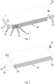
- the Fig. 1 shows a perspective view of an electrode pack 10 in the form of a stack.
- one electrode pack 10 is provided.
- the method is not limited to one electrode pack 10.
- two or more electrode packs 10 arranged side by side can be provided.
- the Fig. 1 illustrates a step of the method in which at least one electrode package 10 is provided with a plurality of anode foils 11 and cathode foils 12 which are separated from one another by separator foils 13.
- the anode foils 11 have anode conductors 21 at their ends, and the cathode foils 12 have cathode conductors 22 at their ends.
- the anode conductors 21 and the cathode conductors 22 protrude from the edges of the cut anode foils 11 and cathode foils 12.
- the anode conductors 21 of the anode foils 11 protrude on a first side S1 of the electrode stack 10
- the cathode conductors 22 of the cathode foils 12 protrude on a second side S2 of the electrode stack 10.
- the anode conductors 21 and the cathode foils 12 are arranged such that the anode conductors 21 and the cathode conductors 22 are aligned.
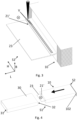
- the Fig. 2 shows a perspective view of an electrode package made of Fig. 1 with bundled arresters 21, 22.
- arrester 21, 22 can be understood as the use of anode arresters 21 and/or cathode arresters 22.
- the Fig. 2 shows a further step of the method according to the invention, in which the anode conductors 21 of the anode foils 11, designed as so-called copper tabs, are first placed centrally or centered relative to the electrode package 10 along a width direction B and then stapled or bundled. Analogous to the first side S1, the cathode conductors 22 of the cathode foils, designed as aluminum tabs, are placed on the second side S2 at the edge of the electrode package 10 and likewise stapled.
- the tackling or bundling of the anode conductors 21 and the cathode conductors 22 to form bundled anode conductors 21' and bundled cathode conductors 22' is carried out, for example, by ultrasonic welding with an anvil (not shown) and a sonotrode.
- the Fig. 2 also shows the use of a conductor extension 23 on the bundled anode conductors 21'.
- the illustrated conductor extension 23 is made, for example, from a solid material and has a material composition that corresponds to a material composition of the bundled anode conductors 21'.
- the conductor extension 23 in the illustrated embodiment consists exclusively of copper or a copper alloy.
- the Fig. 3 shows a detailed view of bundled anode conductors 21' with an anode extension 23 connected by laser welding.
- the bundled anode conductors 21' are extended by an anode extension 23 along a length direction L of the battery cell 100 or the electrode package 10.
- two connecting seams V are introduced, for example, through the bundled anode conductors 21' into the anode extension 23 to create a materially bonded connection.
- the connecting seams V are formed offset parallel to one another along a height direction H and along the length direction L.
- the anode extension 23 is connected at the edges to the bundled anode conductors 21' and forms an electrically conductive extension of the bundled anode conductors 21'.
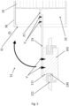
- FIG. 4 A perspective view is shown to illustrate a method step according to an embodiment of the invention, in which the electrode package 10 is inserted into the cell housing 30.
- the electrode package 10 is pushed into the cell housing 30 with the conductor extension 23 leading. This can be done with or without aids, such as foils or insertion tools.
- the cell housing 30 is designed as an extruded profile made of an aluminum alloy and has a first opening 31 on a first side S1 and a second opening 32 on a second side S2.
- the Fig. 5 illustrates in a side sectional view an indirect coupling of the anode conductor 21' to the collector 111 via the conductor extension 23.
- the first battery pole 101 which can be inserted into a first cell cover 121 and electrically insulated from the cell cover 121 by an insulator 130, is brought to the conductor extension 23.
- the arrester extension 23 is welded to the collector 111 of the first cell cover 121.
- the first battery pole 101 which is arranged on a side of the cell cover 121 opposite the collector 111, is designed as a negative pole in the illustrated embodiment.
- the cell lid 121 can be folded by 90°, whereby the bundled anode conductors 21' and the conductor extension 23 are folded and/or bent. This takes place, for example, in the inner volume 33 of the cell housing 30 and is Fig. 6 shown in a lateral sectional view.
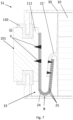
- Fig. 7 a side sectional view illustrating a conductor extension 24 according to a further embodiment.
- the arrester extension 23 shown in the form of a solid material is Fig. 7 a laminated arrester extension 24 is used.
- the laminated arrester extension 24 consists of a plurality of material layers 25 which are connected to one another at least in some areas.
- the respective material layers 25 are connected to one another at the edge-side connection points V.
- the respective material layers 25 are designed, for example, as thin copper foils, allowing such a conductor extension 24 to be folded with little force and within a tight radius. This minimizes the required installation space for the conductor extension 24.
- the cell housing 30 is completely closed.
- an electrolyte solution can be introduced into the interior volume 33 of the cell housing via a filler opening (not shown). This completes a battery cell 100 in the illustrated embodiment.
- the battery cell 100 essentially consists of a cell housing 30, which has at least one electrode pack 10 in an internal volume 33.
- the anode foils 11 of the electrode pack 10 are electrically conductively connected to the first battery terminal 101.
- the cathode foils 12 of the electrode pack 10 are electrically conductively connected to the second battery terminal 102.
- FIG. 9 are side sectional views to illustrate a method according to the invention for producing battery cells 100 according to a another embodiment is shown. This illustrates the attachment of the arrester extension 23 to the first side S1.
- This embodiment of the method differs from the previously described method in that the conductor extension 23 is arranged at different angles ⁇ to ensure optimal tool access for introducing electrically conductive connections V. Furthermore, two electrode packages 10.1, 10.2 are provided, each comprising a bundled anode conductor 21.1', 21.2'. Both anode conductors 21.1', 21.2' are connected to a conductor extension 23.
- the arrester extension 23 is positioned at a first angle ⁇ 1 relative to the first side S1 of the electrode stacks 10.1, 10.2.
- the electrode stacks 10.1, 10.2 are arranged parallel to one another and, in the illustrated embodiment, are flush at the edges.
- the first angle ⁇ 1 is, for example, 55° and enables the introduction of laser weld seams V in overlapping areas between the arrester extension 23 and the anode arresters 21.1', 21.2'.
- the arrester extension 23 can be arranged relative to the anode arresters 21.1', 21.2 ⁇ and the collector 111 with the aid of a holding device 40 or a gripper and adjusted at the angle ⁇ .
- an anode conductor 21.1' of the first electrode stack 10.1 is electrically coupled to a first side 23.1 of the conductor extension 23, and an anode conductor 21.2' of the second electrode stack 10.2 is electrically coupled to a second side 23.2 of the conductor extension 23.
- the conductor extension 23 is bent in advance.
- the conductor extension 23 has an S-shape, which provides a receiving space between the second side 23.2 of the arrester extension 23 and the collector 111 for the bundled anode arresters 21.2 ⁇ .
- the electrode packages 10.1, 10.2 are pushed into the cell housing 30.
- the battery terminal 101 is then electrically connected to the conductor extension 23.
- the conductor extension 23 with the connected anode conductors 21.1', 21.2' is fixed by the gripper 40 to ensure tool access for inserting the electrically conductive connection V.
- the arrows V illustrate in the Fig. 9 example of a tool access of a laser welding device.
- an arrester-side alignment aid 26 is provided.
- the arrester-side alignment aid 26 can be used to interact with a collector-side alignment aid.
- the collector-side alignment aid is not shown for clarity.
- the arrester-side alignment aid 26 is designed as one or more through-holes.
- the collector-side alignment aid can be designed in the form of pins or bulges corresponding to the through-holes.
- the first angle ⁇ 1 is kept constant.
- the gripper 40 can set a second angle ⁇ 2, for example, of 30°.
- the arrester extension 23 can be connected to the collector 111, for example, by soldering or welding.
- the arrester extension 23 can, for example, be welded or soldered directly to the alignment aid 26 in order to form an electrically conductive connection.
- the battery pole 101 with the collector 111 can then be rotated at an angle of 0° to close the cell housing 30.
- the method is illustrated by way of example using the first side S1 of the battery cell 100. Analogously, the method can be implemented on the second side S2 of the battery cell 100 with cathode conductors 22.
Landscapes
- Chemical & Material Sciences (AREA)
- Chemical Kinetics & Catalysis (AREA)
- Electrochemistry (AREA)
- General Chemical & Material Sciences (AREA)
- Engineering & Computer Science (AREA)
- Manufacturing & Machinery (AREA)
- Connection Of Batteries Or Terminals (AREA)
Priority Applications (2)
| Application Number | Priority Date | Filing Date | Title |
|---|---|---|---|
| EP23203626.9A EP4539183A1 (fr) | 2023-10-13 | 2023-10-13 | Fabrication d'éléments de batterie au moyen d'extensions de collecteur de courant |
| PCT/EP2024/078838 WO2025078684A1 (fr) | 2023-10-13 | 2024-10-14 | Production de cellules de batterie au moyen d'extensions de parafoudre |
Applications Claiming Priority (1)
| Application Number | Priority Date | Filing Date | Title |
|---|---|---|---|
| EP23203626.9A EP4539183A1 (fr) | 2023-10-13 | 2023-10-13 | Fabrication d'éléments de batterie au moyen d'extensions de collecteur de courant |
Publications (1)
| Publication Number | Publication Date |
|---|---|
| EP4539183A1 true EP4539183A1 (fr) | 2025-04-16 |
Family
ID=88413307
Family Applications (1)
| Application Number | Title | Priority Date | Filing Date |
|---|---|---|---|
| EP23203626.9A Pending EP4539183A1 (fr) | 2023-10-13 | 2023-10-13 | Fabrication d'éléments de batterie au moyen d'extensions de collecteur de courant |
Country Status (2)
| Country | Link |
|---|---|
| EP (1) | EP4539183A1 (fr) |
| WO (1) | WO2025078684A1 (fr) |
Citations (3)
| Publication number | Priority date | Publication date | Assignee | Title |
|---|---|---|---|---|
| DE102021127860A1 (de) * | 2021-10-26 | 2023-04-27 | Dr. Ing. H.C. F. Porsche Aktiengesellschaft | Verfahren zur Herstellung einer Batteriezelle sowie Batteriezelle |
| EP4191759A1 (fr) * | 2021-12-06 | 2023-06-07 | Toyota Jidosha Kabushiki Kaisha | Batterie secondaire |
| US20230246270A1 (en) * | 2020-05-25 | 2023-08-03 | Samsung Sdi Co., Ltd. | Secondary battery |
-
2023
- 2023-10-13 EP EP23203626.9A patent/EP4539183A1/fr active Pending
-
2024
- 2024-10-14 WO PCT/EP2024/078838 patent/WO2025078684A1/fr active Pending
Patent Citations (3)
| Publication number | Priority date | Publication date | Assignee | Title |
|---|---|---|---|---|
| US20230246270A1 (en) * | 2020-05-25 | 2023-08-03 | Samsung Sdi Co., Ltd. | Secondary battery |
| DE102021127860A1 (de) * | 2021-10-26 | 2023-04-27 | Dr. Ing. H.C. F. Porsche Aktiengesellschaft | Verfahren zur Herstellung einer Batteriezelle sowie Batteriezelle |
| EP4191759A1 (fr) * | 2021-12-06 | 2023-06-07 | Toyota Jidosha Kabushiki Kaisha | Batterie secondaire |
Also Published As
| Publication number | Publication date |
|---|---|
| WO2025078684A1 (fr) | 2025-04-17 |
Similar Documents
| Publication | Publication Date | Title |
|---|---|---|
| DE112013004230B4 (de) | Herstellungsverfahren einer elektrischen Speichervorrichtung und elektrische Speichervorrichtung | |
| DE102008059949A1 (de) | Batterie und Verfahren zur Herstellung einer Batterie | |
| EP2727172A1 (fr) | Dispositif d'accumulation électrique | |
| DE102017209059A1 (de) | Energiespeichereinrichtung, Energiespeichergerät und Verfahren des Herstellens der Energiespeichereinrichtung | |
| WO2013023766A1 (fr) | Couvercle pour boîtier d'un accumulateur d'énergie électrochimique pourvu d'un boîtier de type bac, et procédé de production de ce couvercle | |
| DE102007063184A1 (de) | Einzelzelle für eine Batterie zur elektrischen Kontaktierung | |
| EP2740169A1 (fr) | Élément unitaire pour batterie et batterie | |
| WO2014040734A2 (fr) | Isolation d'accumulateurs d'énergie électrochimiques | |
| DE102017214993A1 (de) | Energiespeichervorrichtung | |
| EP2467886A1 (fr) | Cellule électrochimique | |
| DE102022107471B3 (de) | Batteriezelle und Verfahren zu ihrer Herstellung | |
| EP4324047B1 (fr) | Connecteur de cellule et procédé de mise en contact d'au moins deux cellules galvaniques | |
| DE102016225252A1 (de) | Elektrischer Energiespeicher, insbesondere Batteriezelle, mit Bauraum-optimierter Elektrodenverschaltung | |
| WO2024189174A1 (fr) | Procédé de fabrication d'un élément de batterie doté de deux pôles de batterie disposés sur des côtés opposés | |
| EP2243179B1 (fr) | Procédé de fabrication d'une cellule individuelle pour batterie | |
| EP4539183A1 (fr) | Fabrication d'éléments de batterie au moyen d'extensions de collecteur de courant | |
| WO2014040677A2 (fr) | Élément individuel d'une batterie | |
| DE102021127860A1 (de) | Verfahren zur Herstellung einer Batteriezelle sowie Batteriezelle | |
| DE102022115246A1 (de) | Montagevorrichtung für eine Batterie | |
| DE102021205502A1 (de) | Batteriezelle für eine Fahrzeugbatterie | |
| DE102022125854A1 (de) | Batterie mit Gehäuse, Batterieelementeverbund und Führungselement | |
| EP4641812A1 (fr) | Ensemble d'électrodes avec des conducteurs pouvant être courbés localement | |
| DE102023211199B3 (de) | Verfahren zur Herstellung einer prismatischen Batteriezelle | |
| DE102024131183B3 (de) | Batteriezelle mit Anoden-Anschlussanordnung und Kathoden-Anschlussanordnung und Verfahren zum Herstellen der Batteriezelle | |
| EP4601107A1 (fr) | Procédé de fabrication d'éléments de batterie |
Legal Events
| Date | Code | Title | Description |
|---|---|---|---|
| PUAI | Public reference made under article 153(3) epc to a published international application that has entered the european phase |
Free format text: ORIGINAL CODE: 0009012 |
|
| STAA | Information on the status of an ep patent application or granted ep patent |
Free format text: STATUS: THE APPLICATION HAS BEEN PUBLISHED |
|
| AK | Designated contracting states |
Kind code of ref document: A1 Designated state(s): AL AT BE BG CH CY CZ DE DK EE ES FI FR GB GR HR HU IE IS IT LI LT LU LV MC ME MK MT NL NO PL PT RO RS SE SI SK SM TR |
|
| STAA | Information on the status of an ep patent application or granted ep patent |
Free format text: STATUS: REQUEST FOR EXAMINATION WAS MADE |
|
| 17P | Request for examination filed |
Effective date: 20251016 |
|
| GRAP | Despatch of communication of intention to grant a patent |
Free format text: ORIGINAL CODE: EPIDOSNIGR1 |
|
| STAA | Information on the status of an ep patent application or granted ep patent |
Free format text: STATUS: GRANT OF PATENT IS INTENDED |
|
| GRAS | Grant fee paid |
Free format text: ORIGINAL CODE: EPIDOSNIGR3 |
|
| INTG | Intention to grant announced |
Effective date: 20260303 |
|
| RIC1 | Information provided on ipc code assigned before grant |
Ipc: H01M 10/052 20100101AFI20260220BHEP Ipc: H01M 50/538 20210101ALI20260220BHEP Ipc: H01M 50/54 20210101ALI20260220BHEP Ipc: H01M 50/545 20210101ALI20260220BHEP Ipc: H01M 50/548 20210101ALI20260220BHEP Ipc: H01M 50/553 20210101ALI20260220BHEP Ipc: H01M 50/566 20210101ALI20260220BHEP Ipc: H01M 50/536 20210101ALI20260220BHEP Ipc: H01M 50/627 20210101ALI20260220BHEP |
|
| P01 | Opt-out of the competence of the unified patent court (upc) registered |
Free format text: CASE NUMBER: UPC_APP_0009675_4539183/2026 Effective date: 20260312 |