EP4539205A1 - Composant de gestion thermique, système de gestion thermique, batterie et appareil électrique - Google Patents
Composant de gestion thermique, système de gestion thermique, batterie et appareil électrique Download PDFInfo
- Publication number
- EP4539205A1 EP4539205A1 EP22946108.2A EP22946108A EP4539205A1 EP 4539205 A1 EP4539205 A1 EP 4539205A1 EP 22946108 A EP22946108 A EP 22946108A EP 4539205 A1 EP4539205 A1 EP 4539205A1
- Authority
- EP
- European Patent Office
- Prior art keywords
- thermal management
- medium
- management component
- body portion
- battery
- Prior art date
- Legal status (The legal status is an assumption and is not a legal conclusion. Google has not performed a legal analysis and makes no representation as to the accuracy of the status listed.)
- Pending
Links
Images



Classifications
-
- F—MECHANICAL ENGINEERING; LIGHTING; HEATING; WEAPONS; BLASTING
- F28—HEAT EXCHANGE IN GENERAL
- F28D—HEAT-EXCHANGE APPARATUS, NOT PROVIDED FOR IN ANOTHER SUBCLASS, IN WHICH THE HEAT-EXCHANGE MEDIA DO NOT COME INTO DIRECT CONTACT
- F28D1/00—Heat-exchange apparatus having stationary conduit assemblies for one heat-exchange medium only, the media being in contact with different sides of the conduit wall, in which the other heat-exchange medium is a large body of fluid, e.g. domestic or motor car radiators
- F28D1/02—Heat-exchange apparatus having stationary conduit assemblies for one heat-exchange medium only, the media being in contact with different sides of the conduit wall, in which the other heat-exchange medium is a large body of fluid, e.g. domestic or motor car radiators with heat-exchange conduits immersed in the body of fluid
- F28D1/04—Heat-exchange apparatus having stationary conduit assemblies for one heat-exchange medium only, the media being in contact with different sides of the conduit wall, in which the other heat-exchange medium is a large body of fluid, e.g. domestic or motor car radiators with heat-exchange conduits immersed in the body of fluid with tubular conduits
- F28D1/053—Heat-exchange apparatus having stationary conduit assemblies for one heat-exchange medium only, the media being in contact with different sides of the conduit wall, in which the other heat-exchange medium is a large body of fluid, e.g. domestic or motor car radiators with heat-exchange conduits immersed in the body of fluid with tubular conduits the conduits being straight
- F28D1/0535—Heat-exchange apparatus having stationary conduit assemblies for one heat-exchange medium only, the media being in contact with different sides of the conduit wall, in which the other heat-exchange medium is a large body of fluid, e.g. domestic or motor car radiators with heat-exchange conduits immersed in the body of fluid with tubular conduits the conduits being straight the conduits having a non-circular cross-section
- F28D1/05358—Assemblies of conduits connected side by side or with individual headers, e.g. section type radiators
-
- H—ELECTRICITY
- H01—ELECTRIC ELEMENTS
- H01M—PROCESSES OR MEANS, e.g. BATTERIES, FOR THE DIRECT CONVERSION OF CHEMICAL ENERGY INTO ELECTRICAL ENERGY
- H01M10/00—Secondary cells; Manufacture thereof
- H01M10/60—Heating or cooling; Temperature control
- H01M10/65—Means for temperature control structurally associated with the cells
- H01M10/655—Solid structures for heat exchange or heat conduction
- H01M10/6556—Solid parts with flow channel passages or pipes for heat exchange
-
- B—PERFORMING OPERATIONS; TRANSPORTING
- B60—VEHICLES IN GENERAL
- B60L—PROPULSION OF ELECTRICALLY-PROPELLED VEHICLES; SUPPLYING ELECTRIC POWER FOR AUXILIARY EQUIPMENT OF ELECTRICALLY-PROPELLED VEHICLES; ELECTRODYNAMIC BRAKE SYSTEMS FOR VEHICLES IN GENERAL; MAGNETIC SUSPENSION OR LEVITATION FOR VEHICLES; MONITORING OPERATING VARIABLES OF ELECTRICALLY-PROPELLED VEHICLES; ELECTRIC SAFETY DEVICES FOR ELECTRICALLY-PROPELLED VEHICLES
- B60L50/00—Electric propulsion with power supplied within the vehicle
- B60L50/50—Electric propulsion with power supplied within the vehicle using propulsion power supplied by batteries or fuel cells
- B60L50/60—Electric propulsion with power supplied within the vehicle using propulsion power supplied by batteries or fuel cells using power supplied by batteries
- B60L50/64—Constructional details of batteries specially adapted for electric vehicles
-
- B—PERFORMING OPERATIONS; TRANSPORTING
- B60—VEHICLES IN GENERAL
- B60L—PROPULSION OF ELECTRICALLY-PROPELLED VEHICLES; SUPPLYING ELECTRIC POWER FOR AUXILIARY EQUIPMENT OF ELECTRICALLY-PROPELLED VEHICLES; ELECTRODYNAMIC BRAKE SYSTEMS FOR VEHICLES IN GENERAL; MAGNETIC SUSPENSION OR LEVITATION FOR VEHICLES; MONITORING OPERATING VARIABLES OF ELECTRICALLY-PROPELLED VEHICLES; ELECTRIC SAFETY DEVICES FOR ELECTRICALLY-PROPELLED VEHICLES
- B60L58/00—Methods or circuit arrangements for monitoring or controlling batteries or fuel cells, specially adapted for electric vehicles
- B60L58/10—Methods or circuit arrangements for monitoring or controlling batteries or fuel cells, specially adapted for electric vehicles for monitoring or controlling batteries
- B60L58/24—Methods or circuit arrangements for monitoring or controlling batteries or fuel cells, specially adapted for electric vehicles for monitoring or controlling batteries for controlling the temperature of batteries
- B60L58/26—Methods or circuit arrangements for monitoring or controlling batteries or fuel cells, specially adapted for electric vehicles for monitoring or controlling batteries for controlling the temperature of batteries by cooling
-
- F—MECHANICAL ENGINEERING; LIGHTING; HEATING; WEAPONS; BLASTING
- F28—HEAT EXCHANGE IN GENERAL
- F28F—DETAILS OF HEAT-EXCHANGE AND HEAT-TRANSFER APPARATUS, OF GENERAL APPLICATION
- F28F9/00—Casings; Header boxes; Auxiliary supports for elements; Auxiliary members within casings
- F28F9/02—Header boxes; End plates
- F28F9/0219—Arrangements for sealing end plates into casing or header box; Header box sub-elements
- F28F9/0221—Header boxes or end plates formed by stacked elements
-
- H—ELECTRICITY
- H01—ELECTRIC ELEMENTS
- H01M—PROCESSES OR MEANS, e.g. BATTERIES, FOR THE DIRECT CONVERSION OF CHEMICAL ENERGY INTO ELECTRICAL ENERGY
- H01M10/00—Secondary cells; Manufacture thereof
- H01M10/60—Heating or cooling; Temperature control
- H01M10/61—Types of temperature control
- H01M10/613—Cooling or keeping cold
-
- H—ELECTRICITY
- H01—ELECTRIC ELEMENTS
- H01M—PROCESSES OR MEANS, e.g. BATTERIES, FOR THE DIRECT CONVERSION OF CHEMICAL ENERGY INTO ELECTRICAL ENERGY
- H01M10/00—Secondary cells; Manufacture thereof
- H01M10/60—Heating or cooling; Temperature control
- H01M10/62—Heating or cooling; Temperature control specially adapted for specific applications
- H01M10/625—Vehicles
-
- H—ELECTRICITY
- H01—ELECTRIC ELEMENTS
- H01M—PROCESSES OR MEANS, e.g. BATTERIES, FOR THE DIRECT CONVERSION OF CHEMICAL ENERGY INTO ELECTRICAL ENERGY
- H01M10/00—Secondary cells; Manufacture thereof
- H01M10/60—Heating or cooling; Temperature control
- H01M10/64—Heating or cooling; Temperature control characterised by the shape of the cells
- H01M10/647—Prismatic or flat cells, e.g. pouch cells
-
- H—ELECTRICITY
- H01—ELECTRIC ELEMENTS
- H01M—PROCESSES OR MEANS, e.g. BATTERIES, FOR THE DIRECT CONVERSION OF CHEMICAL ENERGY INTO ELECTRICAL ENERGY
- H01M10/00—Secondary cells; Manufacture thereof
- H01M10/60—Heating or cooling; Temperature control
- H01M10/65—Means for temperature control structurally associated with the cells
- H01M10/656—Means for temperature control structurally associated with the cells characterised by the type of heat-exchange fluid
- H01M10/6561—Gases
- H01M10/6566—Means within the gas flow to guide the flow around one or more cells, e.g. manifolds, baffles or other barriers
-
- H—ELECTRICITY
- H01—ELECTRIC ELEMENTS
- H01M—PROCESSES OR MEANS, e.g. BATTERIES, FOR THE DIRECT CONVERSION OF CHEMICAL ENERGY INTO ELECTRICAL ENERGY
- H01M10/00—Secondary cells; Manufacture thereof
- H01M10/60—Heating or cooling; Temperature control
- H01M10/65—Means for temperature control structurally associated with the cells
- H01M10/656—Means for temperature control structurally associated with the cells characterised by the type of heat-exchange fluid
- H01M10/6567—Liquids
- H01M10/6568—Liquids characterised by flow circuits, e.g. loops, located externally to the cells or cell casings
-
- H—ELECTRICITY
- H01—ELECTRIC ELEMENTS
- H01M—PROCESSES OR MEANS, e.g. BATTERIES, FOR THE DIRECT CONVERSION OF CHEMICAL ENERGY INTO ELECTRICAL ENERGY
- H01M50/00—Constructional details or processes of manufacture of the non-active parts of electrochemical cells other than fuel cells, e.g. hybrid cells
- H01M50/20—Mountings; Secondary casings or frames; Racks, modules or packs; Suspension devices; Shock absorbers; Transport or carrying devices; Holders
- H01M50/204—Racks, modules or packs for multiple batteries or multiple cells
- H01M50/207—Racks, modules or packs for multiple batteries or multiple cells characterised by their shape
- H01M50/209—Racks, modules or packs for multiple batteries or multiple cells characterised by their shape adapted for prismatic or rectangular cells
-
- H—ELECTRICITY
- H01—ELECTRIC ELEMENTS
- H01M—PROCESSES OR MEANS, e.g. BATTERIES, FOR THE DIRECT CONVERSION OF CHEMICAL ENERGY INTO ELECTRICAL ENERGY
- H01M50/00—Constructional details or processes of manufacture of the non-active parts of electrochemical cells other than fuel cells, e.g. hybrid cells
- H01M50/20—Mountings; Secondary casings or frames; Racks, modules or packs; Suspension devices; Shock absorbers; Transport or carrying devices; Holders
- H01M50/249—Mountings; Secondary casings or frames; Racks, modules or packs; Suspension devices; Shock absorbers; Transport or carrying devices; Holders specially adapted for aircraft or vehicles, e.g. cars or trains
-
- F—MECHANICAL ENGINEERING; LIGHTING; HEATING; WEAPONS; BLASTING
- F28—HEAT EXCHANGE IN GENERAL
- F28F—DETAILS OF HEAT-EXCHANGE AND HEAT-TRANSFER APPARATUS, OF GENERAL APPLICATION
- F28F1/00—Tubular elements; Assemblies of tubular elements
- F28F1/02—Tubular elements of cross-section which is non-circular
- F28F1/022—Tubular elements of cross-section which is non-circular with multiple channels
-
- F—MECHANICAL ENGINEERING; LIGHTING; HEATING; WEAPONS; BLASTING
- F28—HEAT EXCHANGE IN GENERAL
- F28F—DETAILS OF HEAT-EXCHANGE AND HEAT-TRANSFER APPARATUS, OF GENERAL APPLICATION
- F28F2220/00—Closure means, e.g. end caps on header boxes or plugs on conduits
-
- F—MECHANICAL ENGINEERING; LIGHTING; HEATING; WEAPONS; BLASTING
- F28—HEAT EXCHANGE IN GENERAL
- F28F—DETAILS OF HEAT-EXCHANGE AND HEAT-TRANSFER APPARATUS, OF GENERAL APPLICATION
- F28F2270/00—Thermal insulation; Thermal decoupling
- F28F2270/02—Thermal insulation; Thermal decoupling by using blind conduits
-
- H—ELECTRICITY
- H01—ELECTRIC ELEMENTS
- H01M—PROCESSES OR MEANS, e.g. BATTERIES, FOR THE DIRECT CONVERSION OF CHEMICAL ENERGY INTO ELECTRICAL ENERGY
- H01M2220/00—Batteries for particular applications
- H01M2220/20—Batteries in motive systems, e.g. vehicle, ship, plane
-
- Y—GENERAL TAGGING OF NEW TECHNOLOGICAL DEVELOPMENTS; GENERAL TAGGING OF CROSS-SECTIONAL TECHNOLOGIES SPANNING OVER SEVERAL SECTIONS OF THE IPC; TECHNICAL SUBJECTS COVERED BY FORMER USPC CROSS-REFERENCE ART COLLECTIONS [XRACs] AND DIGESTS
- Y02—TECHNOLOGIES OR APPLICATIONS FOR MITIGATION OR ADAPTATION AGAINST CLIMATE CHANGE
- Y02E—REDUCTION OF GREENHOUSE GAS [GHG] EMISSIONS, RELATED TO ENERGY GENERATION, TRANSMISSION OR DISTRIBUTION
- Y02E60/00—Enabling technologies; Technologies with a potential or indirect contribution to GHG emissions mitigation
- Y02E60/10—Energy storage using batteries
Definitions
- This application relates to the field of battery technologies, and specifically to, a thermal management component, a thermal management system, a battery, and an electric apparatus.
- a battery consists of a box and a plurality of battery cells accommodated in the box.
- batteries have high requirements in terms of both safety and service life.
- the battery cells inside the battery generate a large amount of heat, causing the internal temperature of the battery to rise sharply. This severely affects the use performance and service life of the battery, and even leads to significant safety risks during use of the battery, which is detrimental to consumer safety.
- Embodiments of this application provide a thermal management component, a thermal management system, a battery, and an electric apparatus, so as to effectively improve the use performance of the battery.
- the thermal management component is provided with the medium inlet, the medium outlet, the cavity, and the medium flow channel, and the medium flow channel communicates with both the medium inlet and the medium outlet and thus can accommodate the fluid medium to regulate the temperature of the battery, which can alleviate the phenomenon of sharp temperature rise inside the battery.
- the cavity is disconnected from both the medium inlet and the medium outlet, preventing the fluid medium from entering the cavity. This not only regulates the temperature of the battery but also reduces the weight of the thermal management component, achieving light weight of the thermal management component.
- the thermal management component includes a body portion, a first fluid collecting member, and a second fluid collecting member.
- the body portion is provided with the medium flow channel and the cavity.
- the first fluid collecting member and the second fluid collecting member are respectively disposed at two ends of the body portion, and the medium inlet and the medium outlet are respectively provided on the first fluid collecting member and the second fluid collecting member.
- the thermal management component is provided with the body portion and the first fluid collecting member and second fluid collecting member connected to the two ends of the body portion in the length direction of the body portion.
- the body portion is provided with the medium flow channel and the cavity, and the medium inlet and the medium outlet are respectively provided on the first fluid collecting member and the second fluid collecting member, so that two ends of the medium flow channel communicate with the medium inlet and the medium outlet respectively, and the cavity does not communicate with the medium inlet and the medium outlet, achieving light weight of the thermal management component.
- Such thermal management component is simple in structure and easy to manufacture.
- the sealing member is detachably connected to the body portion.
- the sealing member is detachably connected to the body portion, allowing for quick removal and replacement of the sealing member. This facilitates sealing of the different passages according to actual needs during use, meeting various use requirements. In addition, this allows for maintenance and replacement of the sealing member, helping to prolong the service life of the thermal management component.
- a first chamber communicating with the medium inlet is formed in the first fluid collecting member, and a second chamber communicating with the medium outlet is formed in the second fluid collecting member.
- the medium flow channel runs through the two ends of the body portion in the length direction of the body portion to communicate with the first chamber and the second chamber.
- the cavity and the medium flow channel both extend along the length direction of the body portion and are arranged along a width direction of the body portion.
- the medium flow channel is provided at the middle position of the body portion in the width direction of the body portion, allowing for heat exchange in positions where the internal heat of the battery is more concentrated, thereby helping to improve the thermal management performance of the thermal management component for the battery.
- the thermal management component is provided with a plurality of medium flow channels and a plurality of cavities, and along the width direction of the body portion, the cavities and the medium flow channels are arranged alternately.
- the cavities and the medium flow channels are arranged alternately along the width direction of the body portion, meaning that there are a plurality of cavities and a plurality of medium flow channels, and the cavities and the medium flow channels are arranged alternately. This achieves a dispersed arrangement of the medium flow channels along the width direction of the body portion, effectively reducing the phenomenon of unbalanced heat exchange capacity of the thermal management component caused by concentrated medium flow channels, thereby improving the use performance of the thermal management component.
- the area occupied by the medium flow channels on the side surface of the body portion is greater than or equal to 20%, reducing the phenomenon of low heat exchange capacity caused by an excessively small area occupied by the medium flow channels, thereby ensuring the heat exchange performance of the thermal management component.
- the thermal management system is provided with the plurality of thermal management components, helping to improve the thermal management capability of the thermal management system for a battery in the battery with such thermal management system, thereby reducing the safety risks caused by internal temperature rise of the battery.
- a medium outlet of one thermal management component communicates with a medium inlet of another thermal management component.
- the medium outlet of one thermal management component communicates with the medium inlet of another thermal management component, achieving a series connection structure of the plurality of thermal management components, thereby facilitating assembly and processing, and allowing for injection of the fluid medium into the medium flow channels of the plurality of thermal management components during use.
- the thermal management component is provided with a plurality of medium flow channels, and along a flow direction of the fluid medium in the medium flow channels of the plurality of thermal management components, in two adjacent ones of the thermal management components, the number of the medium flow channels in a downstream thermal management component is greater than the number of the medium flow channels in an upstream thermal management component.
- the number of the medium flow channels in the downstream thermal management component is greater than the number of the medium flow channels in the upstream thermal management component, helping to improve the heat exchange capacity of the downstream thermal management component, and ensuring balanced heat exchange capacities of the plurality of thermal management components of the thermal management system, thereby improving the overall thermal management capability of the thermal management system, and effectively alleviating the phenomenon of local temperature rise inside the battery.
- the medium inlets of the plurality of thermal management components communicate with each other, and the medium outlets of the plurality of thermal management components communicate with each other.
- the medium inlets of the plurality of thermal management components communicate with each other, and the medium outlets of the plurality of thermal management components communicate with each other, achieving a parallel connection structure of the plurality of thermal management components.
- This allows for simultaneous injection of the fluid medium into the medium flow channels of the plurality of thermal management components.
- this can ensure balanced heat exchange capacity of each thermal management component, thereby effectively alleviating the phenomenon of local temperature rise inside the battery.
- an embodiment of this application further provides a battery including a box, a plurality of battery cells, and the above thermal management system.
- the plurality of battery cells are accommodated in the box; and the thermal management system is disposed in the box, and the thermal management system is used to regulate temperature of the plurality of battery cells.
- the battery cell has a first side surface, the first side surface is a surface with the largest area of outer surfaces of the battery cell, and the first side surface abuts against the thermal management component.
- connection should be understood in their general senses. For example, they may refer to a fixed connection, a detachable connection, or an integral connection, and may refer to a direct connection, an indirect connection via an intermediate medium, or an internal communication between two elements. Persons of ordinary skill in the art can understand specific meanings of these terms in this application as appropriate to specific situations.
- a plurality of means more than two (inclusive).
- the battery cell may include a lithium-ion secondary battery, a lithium-ion primary battery, a lithium-sulfur battery, a sodium-lithium-ion battery, a sodium-ion battery, a magnesium-ion battery, or the like.
- the battery cell may be cylindrical, flat, cuboid, or of other shapes. This is not limited in the embodiments of this application either.
- Battery cells are typically divided into three types by packaging method: cylindrical cell, prismatic cell, and pouch cell. The type of battery cell is not limited in the embodiments of this application either.
- the battery cell includes a housing, an electrode assembly, and an electrolyte.
- the housing is configured to accommodate the electrode assembly and the electrolyte.
- the electrode assembly includes a positive electrode plate, a negative electrode plate, and a separator.
- Working of the battery cell mainly relies on migration of metal ions between the positive electrode plate and the negative electrode plate.
- a battery consists of a box and a plurality of battery cells accommodated in the box.
- batteries have high requirements in terms of both safety and service life.
- a plurality of battery cells in a box of the battery are usually arranged in an array.
- the battery cells generate a large amount of heat, causing the internal temperature of the battery to rise.
- a structure with a plurality of battery cells stacked exacerbates this phenomenon, severely affecting the use performance and service life of the battery, and can even lead to significant safety risks during use of the battery, which is detrimental to consumer safety. Therefore, in the prior art, a water cooling plate is usually provided inside the battery and located on one side of the plurality of battery cells. A passage through which a cooling medium flows is formed in the water cooling plate, so as to cool the battery cells.
- the thermal management component is provided with a medium inlet, a medium outlet, and a medium flow channel.
- the medium flow channel is located inside the thermal management component, the medium flow channel communicates with the medium inlet and the medium outlet, and the medium flow channel is used to accommodate a fluid medium to regulate temperature of the battery.
- the thermal management component is internally provided with a cavity disconnected from both the medium inlet and the medium outlet.
- the thermal management component is provided with the medium inlet, the medium outlet, the cavity, and the medium flow channel, and the medium flow channel communicates with both the medium inlet and the medium outlet and thus can accommodate the fluid medium to regulate the temperature of the battery, which can alleviate the phenomenon of sharp temperature rise inside the battery.
- the cavity is disconnected from both the medium inlet and the medium outlet, preventing the fluid medium from entering the cavity. This not only regulates the temperature of the battery but also reduces the weight of the thermal management component, achieving light weight of the thermal management component.
- this can alleviate an increase in the weight of the thermal management component caused by the fluid medium entering the cavity, thereby effectively reducing the weight of the battery with such thermal management component, helping to increase the energy density of the battery, and improving the use performance of the battery.
- the thermal management component disclosed in embodiments of this application may be used in, but is not limited to, vehicles, ships, aircraft, or other electric apparatus.
- a power supply system of such electric apparatus may include the thermal management system, battery, and other components disclosed in this application. This helps to reduce the overall weight of the battery, thereby improving the energy density and use performance of the battery.
- An embodiment of this application provides an electric apparatus that uses a battery as a power source.
- the electric apparatus may include but is not limited to a mobile phone, a tablet, a laptop computer, an electric toy, an electric tool, an electric bicycle, an electric car, a ship, and a spacecraft.
- the electric toy may be a fixed or mobile electric toy, for example, a game console, an electric toy car, an electric toy ship, and an electric toy airplane.
- the spacecraft may include an airplane, a rocket, a space shuttle, a spaceship, and the like.
- FIG. 1 is a schematic structural diagram of a vehicle 1000 according to some embodiments of this application.
- the vehicle 1000 may be a fossil fuel vehicle, a natural-gas vehicle, or a new energy vehicle, where the new energy vehicle may be a battery electric vehicle, a hybrid electric vehicle, a range-extended vehicle, or the like.
- the vehicle 1000 is provided with a battery 100 inside, where the battery 100 may be arranged at the bottom, front, or rear of the vehicle 1000.
- the battery 100 may be configured to supply power to the vehicle 1000.
- the battery 100 may be used as an operational power supply for the vehicle 1000.
- the vehicle 1000 may further include a controller 200 and a motor 300, where the controller 200 is configured to control the battery 100 to supply power to the motor 300, for example, to satisfy power needs of start, navigation, and driving of the vehicle 1000.
- FIG. 2 is a structural exploded view of a battery 100 according to some embodiments of this application.
- the battery 100 may further include a box 10 and a plurality of battery cells 20, and the plurality of battery cells 20 are accommodated in the box 10.
- the box 10 is configured to provide an accommodating space for the battery cell 20.
- the box 10 may be a variety of structures.
- the box 10 may include a first box body 11 and a second box body 12. The first box body 11 and the second box body 12 fit together so that the first box body 11 and the second box body 12 jointly define an accommodating space for accommodating the battery cell 20.
- the second box body 12 may be a hollow structure with one end open, and the first box body 11 may be a plate-shaped structure, where the first box body 11 covers the open side of the second box body 12 so that the first box body 11 and the second box body 12 jointly define the accommodating space.
- the first box body 11 and the second box body 12 may each be a hollow structure with one side open, and the open side of the first box body 11 is engaged with the open side of the second box body 12.
- the box 10 formed by the first box body 11 and the second box body 12 may be of various shapes, for example, cylinder or cuboid.
- the battery 100 may further include a thermal management system 30, where the thermal management system 30 is disposed inside the box 10, and the thermal management system 30 is used to manage temperature of the battery cells 20 so as to cool the battery cells 20.
- the thermal management system 30 may include a plurality of thermal management components 31. Along the width direction of the battery cells 20, one thermal management component 31 is disposed between two adjacent rows of battery cells 20. The thermal management component 31 is configured to exchange heat with the battery cells 20 so as to manage the temperature of the battery cells 20.
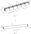
- FIG. 4 is a schematic structural diagram of a thermal management component 31 according to some embodiments of this application.
- This application provides a thermal management component 31, where the thermal management component 31 is provided with a medium inlet 311, a medium outlet 312, and a medium flow channel 313 (not shown in FIG. 4 ).
- the medium flow channel 313 is located inside the thermal management component 31, and the medium flow channel 313 communicates with the medium inlet 311 and the medium outlet 312.
- the medium flow channel 313 is used to accommodate a fluid medium to regulate temperature of the battery 100.
- the thermal management component 31 is internally provided with a cavity 314 (not shown in FIG. 4 ) disconnected from both the medium inlet 311 and the medium outlet 312.
- the medium inlet 311 and the medium outlet 312 are respectively provided at two ends of the thermal management component 31.
- the medium flow channel 313 and the cavity 314 are both provided inside the thermal management component 31.
- the medium flow channel 313 communicates with the medium inlet 311 and the medium outlet 312, meaning that two ends of the medium flow channel 313 respectively communicate with the medium inlet 311 and the medium outlet 312, allowing the fluid medium to flow into or out of the medium flow channel 313.
- the cavity 314 is disconnected from both the medium inlet 311 and the medium outlet 312, meaning that the cavity 314 does not form a connection with the medium inlet 311 and the medium outlet 312, preventing the fluid medium from entering the cavity 314.
- the medium flow channel 313 is used to accommodate the fluid medium, meaning that when flowing through the medium flow channel 313, the fluid medium can exchange heat with the inside of the battery 100 through the thermal management component 31, thereby achieving the function of the thermal management component 31 in managing the internal temperature of the battery 100.
- the fluid medium may be a gas, such as air or hydrogen, or may be a liquid, such as water, a saline solution, or liquid nitrogen.
- the cavity 314 provided inside the thermal management component 31 may be provided in one or in plurality, and similarly, the medium flow channel 313 provided inside the thermal management component 31 may be provided in one or in plurality.
- each medium flow channel 313 communicates with the medium inlet 311 and the medium outlet 312, meaning that two ends of each of the plurality of medium flow channels 313 respectively communicate with the medium inlet 311 and the medium outlet 312.
- a plurality of medium flow channels 313 and a plurality of cavities 314 are provided inside the thermal management component 31.
- the thermal management component 31 is provided with the medium inlet 311, the medium outlet 312, the cavity 314, and the medium flow channel 313, and the medium flow channel 313 communicates with both the medium inlet 311 and the medium outlet 312 and thus can accommodate the fluid medium to regulate the temperature of the battery 100, which can alleviate the phenomenon of sharp temperature rise inside the battery 100.
- the cavity 314 is disconnected from both the medium inlet 311 and the medium outlet 312, preventing the fluid medium from entering the cavity 314. This not only regulates the temperature of the battery 100 but also reduces the weight of the thermal management component 31, achieving light weight of the thermal management component 31.
- this can alleviate an increase in the weight of the thermal management component 31 caused by the fluid medium entering the cavity 314, thereby effectively reducing the weight of the battery 100 with such thermal management component 31, helping to increase the energy density of the battery 100, and improving the use performance of the battery 100.
- FIG. 5 is a cross-sectional view of a body portion 315 of a thermal management component 31 according to some embodiments of this application.
- the thermal management component 31 includes a body portion 315, a first fluid collecting member 316, and a second fluid collecting member 317.
- the body portion 315 is provided with the medium flow channel 313 and the cavity 314.
- the first fluid collecting member 316 and the second fluid collecting member 317 are respectively disposed at two ends of the body portion 315, and the medium inlet 311 and the medium outlet 312 are respectively provided on the first fluid collecting member 316 and the second fluid collecting member 317.
- the medium flow channel 313 and the cavity 314 are both provided inside the body portion 315.
- the medium flow channel 313 and the cavity 314 both extend along the length direction X of the body portion, and two ends of the medium flow channel 313 respectively penetrate through the two ends of the body portion 315, allowing the medium flow channel 313 to communicate with the medium inlet 311 of the first fluid collecting member 316 and the medium outlet 312 of the second fluid collecting member 317.
- the body portion 315, the first fluid collecting member 316, and the second fluid collecting member 317 may be of an integrated structure or a separate structure.
- the body portion 315, the first fluid collecting member 316, and the second fluid collecting member 317 may be made by casting or injection molding.
- the first fluid collecting member 316 and the second fluid collecting member 317 may be connected to the two ends of the body portion 315 by bolting, clamping, or bonding.
- the thermal management component 31 is provided with the body portion 315 and the first fluid collecting member 316 and second fluid collecting member 317 connected to the two ends of the body portion 315 in the length direction X of the body portion.
- the body portion 315 is provided with the medium flow channel 313 and the cavity 314, and the medium inlet 311 and the medium outlet 312 are respectively provided on the first fluid collecting member 316 and the second fluid collecting member 317, so that two ends of the medium flow channel 313 communicate with the medium inlet 311 and the medium outlet 312 respectively, and the cavity 314 does not communicate with the medium inlet 311 and the medium outlet 312, achieving light weight of the thermal management component 31.
- Such thermal management component 31 is simple in structure and easy to manufacture.
- FIG. 6 is a sectional view of a body portion 315 of a thermal management component 31 according to some embodiments of this application.
- the body portion 315 is internally provided with a passage 3151, and the passage 3151 runs through the two ends of the body portion 315 in the length direction X of the body portion.
- the thermal management component 31 further includes a sealing member 318, where the sealing member 318 is connected to the body portion 315, and the sealing member 318 seals two ends of the passage 3151 to form the cavity 314.
- the sealing member 318 is clamped to one end of the passage 3151 to seal the passage 3151.
- the sealing member 318 may alternatively be detachably connected to the body portion 315 by bolting or snapping.
- FIG. 7 is a cross-sectional view of a body portion 315 of a thermal management component 31 according to some other embodiments of this application.
- the cavity 314 may alternatively be a structure integrally formed with the body portion 315, meaning that the cavity 314 is a structure provided with a cavity inside and formed by casting or stamping the body portion 315, that is, the sealing member 318 and the body portion 315 are of an integrated structure.
- the passage 3151 running through the two ends of the body portion 315 in the length direction X of the body portion is formed in the body portion 315 of the thermal management component 31, and the sealing member 318 is disposed on the body portion 315 so that the sealing member 318 seals the two ends of the passage 3151 to form the cavity 314 disconnected from both the medium inlet 311 and the medium outlet 312.
- This structure is simple and easy to manufacture and process, and different passages 3151 can be sealed according to actual needs, expanding the application range of the thermal management component 31.
- the first fluid collecting member 316 is internally provided with a first chamber communicating with the medium inlet 311, and the second fluid collecting member 317 is internally provided with a second chamber communicating with the medium outlet 312.
- the medium flow channel 313 runs through the two ends of the body portion 315 in the length direction X of the body portion to communicate with the first chamber and the second chamber.
- the cavity 314 and the medium flow channel 313 both extend along the length direction X of the body portion and are arranged along a width direction Y of the body portion.
- the cavities 314 and medium flow channels 313 may be arranged alternately; alternatively, the plurality of cavities 314 may be located on one side of the plurality of medium flow channels 313 along the width direction Y of the body portion, or the plurality of cavities 314 may be provided at a middle position of the body portion 315 along the width direction Y of the body portion, where medium flow channels 313 are provided on two sides of the plurality of cavities 314.
- the plurality of cavities 314 may be located on one side of the plurality of medium flow channels 313 along the width direction Y of the body portion, or the plurality of cavities 314 may be provided at a middle position of the body portion 315 along the width direction Y of the body portion, where medium flow channels 313 are provided on two sides of the plurality of cavities 314.
- FIG. 5 in the width direction Y of the body portion, two medium flow channels 313 are provided at the middle position of the body portion 315, three cavities 314 are respectively provided on two sides of the two medium flow channels 313, and the two ends of the body
- the cavity 314 and the medium flow channel 313 both extend along the length direction X of the body portion and are arranged along the width direction Y of the body portion, facilitating the processing and manufacturing of the cavity 314 and the medium flow channel 313 and facilitates the optimization of the arrangement position of the medium flow channel 313, thereby helping to improve the capability of the thermal management component 31 in regulating the temperature of the battery 100.
- the medium flow channel 313 is provided at the middle position of the body portion 315.
- the medium flow channel 313 is provided at the middle position of the body portion 315. If there is one medium flow channel 313, the medium flow channel 313 is positioned at the middle position of the body portion 315. If there are a plurality of medium flow channels 313, at least some of the plurality of medium flow channels 313 are positioned at the middle position of the body portion 315 in the width direction Y of the body portion. For example, in FIG. 5 and FIG. 6 , in the width direction Y of the body portion, two medium flow channels 313 are provided at the middle position of the body portion 315. Certainly, in other embodiments, in the width direction Y of the body portion, one, three, or four medium flow channels 313 may alternatively be provided at the middle position of the body portion 315.
- the medium flow channel 313 is provided at the middle position of the body portion 315 in the width direction of the body portion 315, allowing for heat exchange in positions where the internal heat of the battery 100 is more concentrated, thereby helping to improve the thermal management performance of the thermal management component 31 for the battery 100.
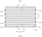
- FIG. 8 is a cross-sectional view of a body portion 315 of a thermal management component 31 according to yet some other embodiments of this application.
- the thermal management component 31 is provided with a plurality of medium flow channels 313 and a plurality of cavities 314, and along the width direction Y of the body portion, the cavities 314 and the medium flow channels 313 are arranged alternately.
- the cavities 314 and medium flow channels 313 are arranged alternately, meaning that the cavities 314 and medium flow channels 313 are arranged alternately along the width direction Y of the body portion.
- a cavity 314 is provided between two adjacent medium flow channels 313, and a medium flow channel 313 is provided between two adjacent cavities 314.
- the cavities 314 and medium flow channels 313 are arranged alternately along the width direction Y of the body portion, meaning that there are a plurality of cavities 314 and a plurality of medium flow channels 313, and the cavities 314 and the medium flow channels 313 are arranged alternately. This achieves a dispersed arrangement of the medium flow channels 313 along the width direction Y of the body portion, effectively reducing the phenomenon of unbalanced heat exchange capacity of the thermal management component 31 caused by concentrated medium flow channels 313, thereby helping to improve the use performance of the thermal management component 31.
- the area of one side surface 3152 is denoted as Si, and the total area of the projections of the medium flow channels 313 on the side surface 3152 is denoted as S 2 , satisfying S 2 /S 1 ⁇ 0.2, meaning that the total area occupied by a plurality of medium flow channels 313 on the side surface 3152 of the body portion 315 is greater than or equal to 20%.
- the area occupied by the plurality of medium flow channels 313 on the side surface 3152 of the body portion 315 is greater than or equal to 20%, reducing the phenomenon of low heat exchange capacity caused by an excessively small area occupied by the medium flow channels 313, thereby ensuring the heat exchange performance of the thermal management component 31.
- the medium outlet 312 of one thermal management component 31 may communicate with the medium inlet 311 of another thermal management component 31 through various structures.
- the medium outlet 312 of one thermal management component 31 may be connected to the medium inlet 311 of another thermal management component 31 or communicate with the medium inlet 311 of another thermal management component 31 through other components such as connecting pipes, to achieve a series connection structure of the plurality of thermal management components 31.
- the medium inlets 311 of the plurality of thermal management components 31 communicate with each other, and the medium outlets 312 of the plurality of thermal management components 31 communicate with each other, achieving a parallel connection structure of the plurality of thermal management components 31.
- This allows for simultaneous injection of the fluid medium into the medium flow channels 313 of the plurality of thermal management components 31.
- this can ensure balanced heat exchange capacity of each thermal management component 31, thereby effectively alleviating the phenomenon of local temperature rise inside the battery 100.
- an embodiment of this application further provides a battery 100.
- the battery 100 includes a box 10, a plurality of battery cells 20, and the thermal management system 30 in any one of the foregoing solutions.
- the plurality of battery cells 20 are accommodated in the box 10.
- the thermal management system 30 is disposed inside the box 10, and the thermal management system 30 is used to regulate temperature of the plurality of battery cells 20.
- the battery cells 20 are cuboid in shape.
- the plurality of battery cells 20 are arranged in rows, where the battery 100 includes multiple rows of battery cells 20, and the multiple rows of battery cells 20 are arranged along a width direction of the battery cells 20.
- Each row of battery cells 20 includes a plurality of battery cells 20 arranged along a length direction of the battery cells 20.
- the first side surface 21 abutting against the thermal management component 31 may mean that the first side surface 21 directly abuts against the thermal management component 31. In other words, the surface with the largest area of the outer surfaces of the battery cell 20 is directly attached to the thermal management component 31.
- the first side surface 21 may alternatively indirectly abut against the thermal management component 31, meaning that the surface with the largest area of the outer surfaces of the battery cell 20 is attached to the thermal management component 31 through a thermal conductive element such as a thermal conductive adhesive.
- the battery cell 20 is cuboid in structure, and the first side surface 21 is the surface with the largest area of the outer surfaces of the battery cell 20, meaning that the first side surface 21 is an outer surface of one side of the battery cell 20 in the width direction of the battery cell 20.
- the thermal management component 31 of the thermal management system 30 is disposed between two adjacent rows of battery cells 20 in the width direction of the battery cell 20, and the body portion 315 of the thermal management component 31 abuts against the first side surface 21 of the battery cell 20, achieving heat exchange between the battery cell 20 and the thermal management component 31.
- the length direction X of the body portion is consistent with the length direction of the battery cell 20, and the thickness direction Z of the body portion is consistent with the width direction of the battery cell 20.
- the thermal management component 31 of the thermal management system 30 abuts against the first side surface 21 of the battery cell 20, meaning that the thermal management component 31 of the thermal management system 30 is disposed on a side with the largest surface area of the battery cell 20, ensuring a sufficient heat exchange area between the battery cell 20 and the thermal management component 31, and helping to improve the thermal management capability of the thermal management component 31 for the battery cell 20, thereby effectively reducing the safety risks caused by temperature rise during the use of the battery 100.
- an embodiment of this application further provides an electric apparatus.
- the electric apparatus includes the battery 100 in any one of the foregoing solutions, and the battery 100 is used to supply electrical energy to the electric apparatus.
- the electric apparatus may be any one of the foregoing devices or systems using the battery 100.
- the thermal management component 31 includes a body portion 315, a first fluid collecting member 316, a second fluid collecting member 317, and a sealing member 318.
- the body portion 315 is internally provided with a medium flow channel 313 and a passage 3151.
- the first fluid collecting member 316 and the second fluid collecting member 317 are respectively disposed at two ends of the body portion 315.
- a medium inlet 311 and a medium outlet 312 are respectively provided on the first fluid collecting member 316 and the second fluid collecting member 317.
- the medium flow channel 313 communicates with both the medium inlet 311 and the medium outlet 312.
- the sealing member 318 is connected to the body portion 315 and the sealing member 318 seals two ends of the passage 3151 to form a cavity 314, where the cavity 314 is disconnected from both the medium inlet 311 and the medium outlet 312.
- the first fluid collecting member 316 is internally provided with a first chamber communicating with the medium inlet 311, and the second fluid collecting member 317 is internally provided with a second chamber communicating with the medium outlet 312.
- the medium flow channel 313 runs through the two ends of the body portion 315 in the length direction X of the body portion to communicate with the first chamber and the second chamber.
Landscapes
- Engineering & Computer Science (AREA)
- Chemical & Material Sciences (AREA)
- General Chemical & Material Sciences (AREA)
- Electrochemistry (AREA)
- Chemical Kinetics & Catalysis (AREA)
- Manufacturing & Machinery (AREA)
- Mechanical Engineering (AREA)
- Power Engineering (AREA)
- Transportation (AREA)
- Life Sciences & Earth Sciences (AREA)
- Sustainable Energy (AREA)
- Sustainable Development (AREA)
- Physics & Mathematics (AREA)
- Thermal Sciences (AREA)
- General Engineering & Computer Science (AREA)
- Aviation & Aerospace Engineering (AREA)
- Secondary Cells (AREA)
- Battery Mounting, Suspending (AREA)
Applications Claiming Priority (1)
| Application Number | Priority Date | Filing Date | Title |
|---|---|---|---|
| PCT/CN2022/098447 WO2023240407A1 (fr) | 2022-06-13 | 2022-06-13 | Composant de gestion thermique, système de gestion thermique, batterie et appareil électrique |
Publications (2)
| Publication Number | Publication Date |
|---|---|
| EP4539205A1 true EP4539205A1 (fr) | 2025-04-16 |
| EP4539205A4 EP4539205A4 (fr) | 2025-08-06 |
Family
ID=86710219
Family Applications (1)
| Application Number | Title | Priority Date | Filing Date |
|---|---|---|---|
| EP22946108.2A Pending EP4539205A4 (fr) | 2022-06-13 | 2022-06-13 | Composant de gestion thermique, système de gestion thermique, batterie et appareil électrique |
Country Status (5)
| Country | Link |
|---|---|
| US (1) | US12586843B2 (fr) |
| EP (1) | EP4539205A4 (fr) |
| JP (1) | JP2025519618A (fr) |
| CN (2) | CN116547856B (fr) |
| WO (1) | WO2023240407A1 (fr) |
Families Citing this family (3)
| Publication number | Priority date | Publication date | Assignee | Title |
|---|---|---|---|---|
| WO2023240407A1 (fr) * | 2022-06-13 | 2023-12-21 | 宁德时代新能源科技股份有限公司 | Composant de gestion thermique, système de gestion thermique, batterie et appareil électrique |
| CN121219884A (zh) * | 2024-04-24 | 2025-12-26 | 宁德时代新能源科技股份有限公司 | 电池装置和用电装置 |
| WO2026025387A1 (fr) * | 2024-07-31 | 2026-02-05 | 宁德时代新能源科技股份有限公司 | Appareil de batterie et appareil électrique |
Family Cites Families (43)
| Publication number | Priority date | Publication date | Assignee | Title |
|---|---|---|---|---|
| US7045236B1 (en) * | 2001-08-10 | 2006-05-16 | Johnson Controls Technology Company | Heat and gas exchange system for battery |
| DE102006017434B4 (de) * | 2005-08-04 | 2020-03-12 | Hanon Systems | Mehrflutiger Wärmeübertrager |
| US7851080B2 (en) * | 2008-04-09 | 2010-12-14 | Gm Global Technology Operations, Inc. | Battery cooling plate design with discrete channels |
| DE102008027293A1 (de) * | 2008-06-06 | 2009-12-10 | Behr Gmbh & Co. Kg | Vorrichtung zur Kühlung einer Fahrzeugbatterie |
| JP5496604B2 (ja) * | 2009-10-30 | 2014-05-21 | 三洋電機株式会社 | 電源装置及びこれを備える車両 |
| CA3053807A1 (fr) | 2010-10-29 | 2012-05-03 | Dana Canada Corporation | Echangeur de chaleur et structure d'unite de batterie pour refroidir des batteries thermiquement conductrices |
| US8722223B2 (en) | 2011-09-01 | 2014-05-13 | Samsung Sdi Co., Ltd. | Battery pack |
| KR20150087515A (ko) * | 2014-01-22 | 2015-07-30 | 삼성에스디아이 주식회사 | 배터리 팩의 열교환부재 |
| US20180123201A1 (en) * | 2016-10-28 | 2018-05-03 | Inevit, Llc | Battery module cooling tube including an integrated turbulator component and method thereof |
| CN206370478U (zh) * | 2016-11-14 | 2017-08-01 | 深圳市赛尔盈电子有限公司 | 一种动力电池冷却和加热集成系统及电池 |
| KR102740288B1 (ko) | 2017-01-12 | 2024-12-09 | 삼성에스디아이 주식회사 | 배터리 팩 하우징 및 이를 포함하는 배터리 팩 |
| KR101929988B1 (ko) * | 2017-07-19 | 2018-12-18 | 주식회사 고산 | 배터리 냉각용 열교환기 |
| JP7085555B2 (ja) * | 2017-08-22 | 2022-06-16 | ビークルエナジージャパン株式会社 | 電池パック |
| BR112020005831A2 (pt) | 2017-10-06 | 2020-09-24 | Norma U.S. Holding Llc | segmento de tubulação de gerenciamento térmico de bateria e conjunto do mesmo |
| CN207938738U (zh) * | 2018-01-30 | 2018-10-02 | 宁德时代新能源科技股份有限公司 | 电池管理系统 |
| CN108448205A (zh) * | 2018-05-08 | 2018-08-24 | 福建省汽车工业集团云度新能源汽车股份有限公司 | 一种电池模组散热装置 |
| CN208674208U (zh) * | 2018-08-01 | 2019-03-29 | 江苏奥特帕斯新能源科技有限公司 | 一种液冷一体化电池托盘 |
| CN209282249U (zh) * | 2018-11-08 | 2019-08-20 | 河南速达电动汽车科技有限公司 | 电动车及其电池箱箱体、电池箱 |
| CN109713178A (zh) | 2018-12-04 | 2019-05-03 | 力神动力电池系统有限公司 | 一种动力电池水冷模组 |
| CN209071461U (zh) * | 2018-12-28 | 2019-07-05 | 宁德时代新能源科技股份有限公司 | 热管理装置及电池包 |
| CN110010995A (zh) * | 2019-04-09 | 2019-07-12 | 华南理工大学 | 一种基于平板热管的电池组热管理系统及其工作方法 |
| CN109962319A (zh) * | 2019-04-19 | 2019-07-02 | 中国第一汽车股份有限公司 | 一种ev动力电池液冷板总成 |
| KR102905222B1 (ko) | 2019-09-03 | 2025-12-29 | 현대모비스 주식회사 | 배터리 냉각을 위한 벤딩튜브형 냉각장치 및 방법 |
| CN211017317U (zh) * | 2019-11-04 | 2020-07-14 | 清华大学苏州汽车研究院(相城) | 一种电池箱 |
| JP7424033B2 (ja) * | 2019-12-19 | 2024-01-30 | 株式会社デンソー | 温度調整装置 |
| CN211829107U (zh) * | 2019-12-31 | 2020-10-30 | 广东工业大学 | 一种用于电池热管理的蜂窝型微通道冷却板 |
| JP2021140965A (ja) * | 2020-03-06 | 2021-09-16 | 株式会社デンソー | 温度調整装置およびその製造方法 |
| CN211789374U (zh) * | 2020-04-13 | 2020-10-27 | 恒大新能源汽车投资控股集团有限公司 | 电池包液冷底板总成和电池包 |
| CN212485434U (zh) * | 2020-04-26 | 2021-02-05 | 天津市捷威动力工业有限公司 | 一种电池包箱体及电池包 |
| CN212277304U (zh) * | 2020-06-18 | 2021-01-01 | 中南林业科技大学 | 一种双向流道电池冷却板及液冷动力电池模组 |
| WO2022006894A1 (fr) | 2020-07-10 | 2022-01-13 | 宁德时代新能源科技股份有限公司 | Batterie et appareil associé correspondant, procédé de préparation et dispositif de préparation |
| CN213459871U (zh) * | 2020-10-20 | 2021-06-15 | 欣旺达电动汽车电池有限公司 | 电池箱的液冷导流边框、集成冷却系统及电池箱 |
| WO2022099661A1 (fr) * | 2020-11-13 | 2022-05-19 | 江苏时代新能源科技有限公司 | Boîtier, batterie, dispositif électrique et procédé de fabrication de batterie |
| CN214254530U (zh) * | 2021-01-08 | 2021-09-21 | 宁德时代新能源科技股份有限公司 | 电池及包括该电池的装置 |
| CN113036262A (zh) * | 2021-03-09 | 2021-06-25 | 宁波大学 | 电池模组均衡散热装置 |
| CN215119024U (zh) | 2021-03-09 | 2021-12-10 | 厦门海辰新能源科技有限公司 | 一种圆柱电池模组换热装置 |
| CN214378603U (zh) * | 2021-03-10 | 2021-10-08 | 南京林业大学 | 一种用于电动汽车锂离子电池的热管理装置 |
| CN214957123U (zh) | 2021-07-05 | 2021-11-30 | 天津市捷威动力工业有限公司 | 一种软包电芯模组 |
| CN113797462A (zh) | 2021-08-24 | 2021-12-17 | 国网福建省电力有限公司 | 一种新型储能集装箱消防系统 |
| EP4318740B1 (fr) * | 2021-08-31 | 2025-11-05 | Contemporary Amperex Technology (Hong Kong) Limited | Élément de batterie, batterie, dispositif électrique et procédé de fabrication de batterie |
| CN216354436U (zh) * | 2021-11-30 | 2022-04-19 | 宁德时代新能源科技股份有限公司 | 电池的换热机构、电池及用电装置 |
| WO2023240407A1 (fr) * | 2022-06-13 | 2023-12-21 | 宁德时代新能源科技股份有限公司 | Composant de gestion thermique, système de gestion thermique, batterie et appareil électrique |
| CN114497826B (zh) * | 2022-04-18 | 2022-08-26 | 宁德时代新能源科技股份有限公司 | 水冷板组件、水冷系统、电池及其箱体以及用电装置 |
-
2022
- 2022-06-13 WO PCT/CN2022/098447 patent/WO2023240407A1/fr not_active Ceased
- 2022-06-13 EP EP22946108.2A patent/EP4539205A4/fr active Pending
- 2022-06-13 JP JP2024572696A patent/JP2025519618A/ja active Pending
- 2022-06-13 CN CN202280007250.0A patent/CN116547856B/zh active Active
- 2022-12-29 CN CN202223599568.9U patent/CN219203302U/zh active Active
-
2024
- 2024-12-12 US US18/979,384 patent/US12586843B2/en active Active
Also Published As
| Publication number | Publication date |
|---|---|
| WO2023240407A1 (fr) | 2023-12-21 |
| EP4539205A4 (fr) | 2025-08-06 |
| US12586843B2 (en) | 2026-03-24 |
| CN219203302U (zh) | 2023-06-16 |
| CN116547856A (zh) | 2023-08-04 |
| US20250112296A1 (en) | 2025-04-03 |
| JP2025519618A (ja) | 2025-06-26 |
| KR20250024054A (ko) | 2025-02-18 |
| CN116547856B (zh) | 2024-08-16 |
Similar Documents
| Publication | Publication Date | Title |
|---|---|---|
| US12586843B2 (en) | Thermal management component, thermal management system, battery, and electric apparatus | |
| US20250226486A1 (en) | Fluid collector, thermal management assembly, battery, and electric apparatus | |
| CN214254530U (zh) | 电池及包括该电池的装置 | |
| CN217182265U (zh) | 电池和用电设备 | |
| US20250055063A1 (en) | Thermal management assembly, battery, and electric apparatus | |
| JP7637136B2 (ja) | 電池、電力消費機器、電池の製造方法及び機器 | |
| CN221552006U (zh) | 电池、换热组件、用电装置及储能装置 | |
| EP4510302A1 (fr) | Composant de gestion thermique, batterie et dispositif électrique | |
| CN117981143A (zh) | 电池热管理系统、电池及用电装置 | |
| US20250286167A1 (en) | Thermal management component, thermal management assembly, battery, and electric device | |
| WO2024124689A1 (fr) | Batterie et dispositif électrique | |
| CN121219887A (zh) | 电池装置和用电装置 | |
| CN220585365U (zh) | 一种电池的冷却组件、电池以及用电装置 | |
| US20230268588A1 (en) | Battery, power consumption device, and method and device for producing battery | |
| US20250246710A1 (en) | Heat exchanging assembly, battery module, battery, electrical device | |
| US20250293342A1 (en) | Battery and electric device | |
| CN221551986U (zh) | 电池单体及其壳体组件、电池和用电装置 | |
| CN221304809U (zh) | 电池及用电装置 | |
| CN223181223U (zh) | 电池装置及用电装置 | |
| CN223427579U (zh) | 电池装置和用电装置 | |
| US20250096359A1 (en) | Battery and electric apparatus | |
| CN222483507U (zh) | 换热组件、电池以及用电装置 | |
| CN120767489B (zh) | 电池装置、用电装置、储能装置、储能系统及充电网络 | |
| CN219591573U (zh) | 电池的端板、电池及用电装置 | |
| US20250340095A1 (en) | Heat exchange assembly, battery, vehicle, and electric device |
Legal Events
| Date | Code | Title | Description |
|---|---|---|---|
| STAA | Information on the status of an ep patent application or granted ep patent |
Free format text: STATUS: THE INTERNATIONAL PUBLICATION HAS BEEN MADE |
|
| PUAI | Public reference made under article 153(3) epc to a published international application that has entered the european phase |
Free format text: ORIGINAL CODE: 0009012 |
|
| STAA | Information on the status of an ep patent application or granted ep patent |
Free format text: STATUS: REQUEST FOR EXAMINATION WAS MADE |
|
| 17P | Request for examination filed |
Effective date: 20250113 |
|
| AK | Designated contracting states |
Kind code of ref document: A1 Designated state(s): AL AT BE BG CH CY CZ DE DK EE ES FI FR GB GR HR HU IE IS IT LI LT LU LV MC MK MT NL NO PL PT RO RS SE SI SK SM TR |
|
| A4 | Supplementary search report drawn up and despatched |
Effective date: 20250707 |
|
| RIC1 | Information provided on ipc code assigned before grant |
Ipc: H01M 10/613 20140101AFI20250701BHEP Ipc: H01M 10/625 20140101ALI20250701BHEP Ipc: H01M 10/647 20140101ALI20250701BHEP Ipc: H01M 10/6557 20140101ALI20250701BHEP Ipc: F28D 1/053 20060101ALI20250701BHEP Ipc: F28F 1/02 20060101ALI20250701BHEP |
|
| RAP3 | Party data changed (applicant data changed or rights of an application transferred) |
Owner name: CONTEMPORARY AMPEREX TECHNOLOGY(HONG KONG) LIMITED |
|
| DAV | Request for validation of the european patent (deleted) | ||
| DAX | Request for extension of the european patent (deleted) |