EP4539206A1 - Support de batterie à refroidissement par fluide - Google Patents
Support de batterie à refroidissement par fluide Download PDFInfo
- Publication number
- EP4539206A1 EP4539206A1 EP23202697.1A EP23202697A EP4539206A1 EP 4539206 A1 EP4539206 A1 EP 4539206A1 EP 23202697 A EP23202697 A EP 23202697A EP 4539206 A1 EP4539206 A1 EP 4539206A1
- Authority
- EP
- European Patent Office
- Prior art keywords
- battery holder
- base plate
- battery
- holder according
- fluid
- Prior art date
- Legal status (The legal status is an assumption and is not a legal conclusion. Google has not performed a legal analysis and makes no representation as to the accuracy of the status listed.)
- Pending
Links
Images


Classifications
-
- H—ELECTRICITY
- H01—ELECTRIC ELEMENTS
- H01M—PROCESSES OR MEANS, e.g. BATTERIES, FOR THE DIRECT CONVERSION OF CHEMICAL ENERGY INTO ELECTRICAL ENERGY
- H01M10/00—Secondary cells; Manufacture thereof
- H01M10/60—Heating or cooling; Temperature control
- H01M10/65—Means for temperature control structurally associated with the cells
- H01M10/655—Solid structures for heat exchange or heat conduction
- H01M10/6556—Solid parts with flow channel passages or pipes for heat exchange
-
- H—ELECTRICITY
- H01—ELECTRIC ELEMENTS
- H01M—PROCESSES OR MEANS, e.g. BATTERIES, FOR THE DIRECT CONVERSION OF CHEMICAL ENERGY INTO ELECTRICAL ENERGY
- H01M10/00—Secondary cells; Manufacture thereof
- H01M10/60—Heating or cooling; Temperature control
- H01M10/61—Types of temperature control
- H01M10/613—Cooling or keeping cold
-
- H—ELECTRICITY
- H01—ELECTRIC ELEMENTS
- H01M—PROCESSES OR MEANS, e.g. BATTERIES, FOR THE DIRECT CONVERSION OF CHEMICAL ENERGY INTO ELECTRICAL ENERGY
- H01M10/00—Secondary cells; Manufacture thereof
- H01M10/60—Heating or cooling; Temperature control
- H01M10/62—Heating or cooling; Temperature control specially adapted for specific applications
- H01M10/625—Vehicles
-
- H—ELECTRICITY
- H01—ELECTRIC ELEMENTS
- H01M—PROCESSES OR MEANS, e.g. BATTERIES, FOR THE DIRECT CONVERSION OF CHEMICAL ENERGY INTO ELECTRICAL ENERGY
- H01M10/00—Secondary cells; Manufacture thereof
- H01M10/60—Heating or cooling; Temperature control
- H01M10/64—Heating or cooling; Temperature control characterised by the shape of the cells
- H01M10/643—Cylindrical cells
-
- H—ELECTRICITY
- H01—ELECTRIC ELEMENTS
- H01M—PROCESSES OR MEANS, e.g. BATTERIES, FOR THE DIRECT CONVERSION OF CHEMICAL ENERGY INTO ELECTRICAL ENERGY
- H01M10/00—Secondary cells; Manufacture thereof
- H01M10/60—Heating or cooling; Temperature control
- H01M10/65—Means for temperature control structurally associated with the cells
- H01M10/655—Solid structures for heat exchange or heat conduction
- H01M10/6554—Rods or plates
-
- H—ELECTRICITY
- H01—ELECTRIC ELEMENTS
- H01M—PROCESSES OR MEANS, e.g. BATTERIES, FOR THE DIRECT CONVERSION OF CHEMICAL ENERGY INTO ELECTRICAL ENERGY
- H01M10/00—Secondary cells; Manufacture thereof
- H01M10/60—Heating or cooling; Temperature control
- H01M10/65—Means for temperature control structurally associated with the cells
- H01M10/656—Means for temperature control structurally associated with the cells characterised by the type of heat-exchange fluid
- H01M10/6567—Liquids
-
- H—ELECTRICITY
- H01—ELECTRIC ELEMENTS
- H01M—PROCESSES OR MEANS, e.g. BATTERIES, FOR THE DIRECT CONVERSION OF CHEMICAL ENERGY INTO ELECTRICAL ENERGY
- H01M10/00—Secondary cells; Manufacture thereof
- H01M10/60—Heating or cooling; Temperature control
- H01M10/65—Means for temperature control structurally associated with the cells
- H01M10/656—Means for temperature control structurally associated with the cells characterised by the type of heat-exchange fluid
- H01M10/6569—Fluids undergoing a liquid-gas phase change or transition, e.g. evaporation or condensation
-
- H—ELECTRICITY
- H01—ELECTRIC ELEMENTS
- H01M—PROCESSES OR MEANS, e.g. BATTERIES, FOR THE DIRECT CONVERSION OF CHEMICAL ENERGY INTO ELECTRICAL ENERGY
- H01M50/00—Constructional details or processes of manufacture of the non-active parts of electrochemical cells other than fuel cells, e.g. hybrid cells
- H01M50/20—Mountings; Secondary casings or frames; Racks, modules or packs; Suspension devices; Shock absorbers; Transport or carrying devices; Holders
- H01M50/204—Racks, modules or packs for multiple batteries or multiple cells
-
- H—ELECTRICITY
- H01—ELECTRIC ELEMENTS
- H01M—PROCESSES OR MEANS, e.g. BATTERIES, FOR THE DIRECT CONVERSION OF CHEMICAL ENERGY INTO ELECTRICAL ENERGY
- H01M50/00—Constructional details or processes of manufacture of the non-active parts of electrochemical cells other than fuel cells, e.g. hybrid cells
- H01M50/20—Mountings; Secondary casings or frames; Racks, modules or packs; Suspension devices; Shock absorbers; Transport or carrying devices; Holders
- H01M50/249—Mountings; Secondary casings or frames; Racks, modules or packs; Suspension devices; Shock absorbers; Transport or carrying devices; Holders specially adapted for aircraft or vehicles, e.g. cars or trains
-
- H—ELECTRICITY
- H01—ELECTRIC ELEMENTS
- H01M—PROCESSES OR MEANS, e.g. BATTERIES, FOR THE DIRECT CONVERSION OF CHEMICAL ENERGY INTO ELECTRICAL ENERGY
- H01M50/00—Constructional details or processes of manufacture of the non-active parts of electrochemical cells other than fuel cells, e.g. hybrid cells
- H01M50/30—Arrangements for facilitating escape of gases
-
- H—ELECTRICITY
- H01—ELECTRIC ELEMENTS
- H01M—PROCESSES OR MEANS, e.g. BATTERIES, FOR THE DIRECT CONVERSION OF CHEMICAL ENERGY INTO ELECTRICAL ENERGY
- H01M2220/00—Batteries for particular applications
- H01M2220/20—Batteries in motive systems, e.g. vehicle, ship, plane
-
- Y—GENERAL TAGGING OF NEW TECHNOLOGICAL DEVELOPMENTS; GENERAL TAGGING OF CROSS-SECTIONAL TECHNOLOGIES SPANNING OVER SEVERAL SECTIONS OF THE IPC; TECHNICAL SUBJECTS COVERED BY FORMER USPC CROSS-REFERENCE ART COLLECTIONS [XRACs] AND DIGESTS
- Y02—TECHNOLOGIES OR APPLICATIONS FOR MITIGATION OR ADAPTATION AGAINST CLIMATE CHANGE
- Y02E—REDUCTION OF GREENHOUSE GAS [GHG] EMISSIONS, RELATED TO ENERGY GENERATION, TRANSMISSION OR DISTRIBUTION
- Y02E60/00—Enabling technologies; Technologies with a potential or indirect contribution to GHG emissions mitigation
- Y02E60/10—Energy storage using batteries
Definitions
- the disclosure relates generally to battery packs for vehicles.
- the disclosure relates to a battery pack comprising a fluid cooling solution.
- the disclosure can be applied to heavy-duty vehicles, such as trucks, buses, and construction equipment, among other vehicle types.
- the disclosure can be applied to marine vessels and the like.
- Maintaining the ideal temperature range within a battery pack is essential for both short-term performance and long-term durability.
- Precise temperature control ensures that the battery operates at its peak efficiency, delivering the expected capacity and output power for a wide range of applications.
- uniform temperature distribution across the battery module is critical to prevent localized stress and uneven cell performance. Inconsistent temperatures can lead to reduced overall performance, capacity loss, uneven aging between cells and safety concerns. Therefore, it is desirable to develop cooling solutions which are both efficient and which promotes a uniform temperature distribution in a battery pack.
- a battery holder for holding a plurality of battery cells for a vehicle, the battery holder having a base plate comprising: a plurality of through openings, each opening being configured to allow venting of gas from a battery cell; and a closed compartment being partially filled with a fluid.
- the first aspect of the disclosure may seek to improve cooling in a battery pack by providing a fluid-filled compartment where the fluid acts to spread heat generated by battery cells, thereby reducing the risk of uneven temperature distribution in a battery comprising a plurality of battery cells.
- the closed compartment extends throughout the extension of the base plate in the plane of the base plate.
- a technical benefit may include that heat can be spread evenly over the entire battery holder, thereby facilitating an even temperature distribution throughout the battery holder.
- the closed compartment comprises a plurality of sub-compartments, each sub-compartment being partially filled with a fluid.
- a technical benefit may include that the size and shape of sub-compartments can be adapted to a distribution of battery cells in the battery holder.
- the base plate further comprises at least one groove arranged on a side of the base plate opposite the side configured to hold the battery cell and extending to at least a first edge portion of the base plate, and wherein each through-opening ends in the at least one groove.
- the groove can act as a vent channel in case of a thermal runaway event where heated gases and particles need to be lead away from the battery cells to avoid a chain reaction within the battery. That the through openings lead to the groove also means that any heated gas or particles is cooled by the fluid in the closed compartment both in the flow path from the battery cell to the groove, i.e. through the through opening, as well as when flowing in the groove as such.
- the at least one groove is substantially straight.
- a technical benefit may include that the flow through the groove is uninterrupted, providing a flow path with a low flow resistance.
- an interior surface of the closed compartment comprises surface structures configured to facilitate heat transfer between the base plate and the fluid.
- a technical benefit may include that heat transfer between battery cells and the fluid in the closed compartment can be improved owing to the increased surface area of the interior walls.
- the through openings comprise sidewalls located between the opening and the closed compartment so that the fluid is in contact with the sidewalls.
- a technical benefit may include that gas and particles flowing from battery cells can be cooled by the fluid also during passage through the through openings.
- the fluid comprises a phase change material.
- a technical benefit may include that the phase change material in the closed compartment is fluid only at temperatures where cooling or heat redistribution is required.
- phase change material has a phase change temperature for transformation from solid phase to liquid phase in the range of 35°C to 45°C.
- a technical benefit may include that the phase change material is in solid form up to temperatures which may damage the battery cells.
- the phase change material has a phase change temperature for transformation from solid phase to liquid phase in the range of 110°C to 130°C.
- a technical benefit may include that the phase change material is in solid form up to temperatures which indicate the onset of a thermal runaway event.
- the fluid comprises a mix of materials.
- a technical benefit may include that the properties of the fluid can be tailored to suit any particular application in terms of for example fluidity, flammability, heat capacity etc.
- the fluid is selected from the group comprising dielectric oil, water glycol and water.
- a technical benefit may include that the fluid has a high heat capacity leading to efficient heat redistribution and resistance to temperature increase.
- a further benefit may include that a dielectric fluid is reducing the risk of electrical faults in surrounding system and in a battery in case of leakage of the fluid.
- a fill level of fluid in the closed compartment is in the range of 50% to 70%.
- a technical benefit may include that the fluid is then allowed to splash around to efficiently transfer heat within the compartment.
- a vehicle comprising a battery holder according to any one of the preceding claims.
- a technical benefit may include that efficient heat redistribution can be achieved in an electrical or hybrid vehicle equipped with the described battery holder.
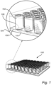
- Fig. 1 is an exemplary battery holder 100 for holding a plurality of battery cells 102 in a vehicle according to an example.
- the battery holder has a base plate 104 comprising: a plurality of through openings 106, each opening being configured to allow venting of gas from a battery cell; and a closed compartment 108 being partially filled with a fluid 110.
- the through openings 106 are preferably arranged in locations corresponding to intended locations of battery cells 102 such that each battery cell is located in alignment with a corresponding through opening.
- battery cells may be provided with adapted portions which are configured to vent the battery cell in case of thermal runaway, and such a vent of the battery cell is then preferably aligned with the through opening to guide gas from the battery cell in a controlled manner via the through opening 106 of the base plate 104.
- the battery holder of Fig. 1 illustrates a plurality of battery cells arranged on a partially hollow base plate 104.
- the battery cells may increase in temperature during operation and to avoid hotspots or regions in the battery as a whole having a higher temperature, it is desirable to provide a cooling solution distributing heat evenly over the battery holder 100.
- the fluid 110 in the partially filled closed compartment 108 can be expected to splash around in the compartment 108 which efficiently redistributes heat in the base plate 104.
- the closed compartment 108 is a fully closed and hermetically sealed compartment 108, at least during operation of a battery using the described battery holder 100.
- filling the proposed void formed by the closed compartment 108 with a fluid 110 using an optimized filling ratio leads to liquid sloshing while driving. This improves the convective heat transfer which is typically quicker than other methods of heat transfer, in turn leading to more even distribution of the heat inside the base plate 104.
- the described cooling solution requires no moving parts, no fluid connection susceptible to leaks, and no additional components outside of the base plate itself.
- the described battery holder 100 thereby offers a simple, compact, reliable, and cost efficient cooling solution for achieving an even heat distribution in a battery holder.
- the fluid 110 in the closed compartment may be a single fluid or a mix of different fluids.
- the fluid comprises a material with high specific heat having a high ability to absorb and store thermal energy.
- An advantage of using high heat capacity materials inside a battery holder as described herein is that the fluid can be used to reduce active cooling power for recirculated coolant and provide protection from extreme and rapid temperature fluctuations.
- aluminum has a specific heat of 0.89 J/(k.s) and water has a specific heat of 4.18J/(k.s).
- the described battery holder provides approximately 70% higher thermal mass compared to a solid aluminum plate.
- the content of the filling can be adjusted by combining different materials, such as a mix of Phase Change Materials (PCM) and liquid to control the behaviour of the fluid for increasing temperatures.
- PCM Phase Change Materials
- the fluid 110 may thus comprise a phase change material which is in solid form at a normal operating temperature of the battery.
- the phase change material may for example be provided as particles, granules or the like which are solid at temperature below a predetermined threshold temperature.
- the phase change material can then be mixed into the fluid at an appropriate proportion, while maintaining the compartment only partially filled to allow splashing and motion of the mixture.
- the phase change material may have a phase change temperature for transformation from solid phase to liquid phase in the range of 20°C to 30°C.
- the phase change material may also have a phase change temperature for transformation from solid phase to liquid phase in the range of 35°C to 45°C.
- the phase change material may further have a phase change temperature for transformation from solid phase to liquid phase in the range of 110°C to 130°C.
- the phase change materials provide additional resistance to heating at the respective phase change temperatures, where the temperature range 20°C to 30°C correspond to a normal operating temperature of the battery cells, 35°C to 45°C correspond to a temperature which is becoming harmful for the battery cells, and where a temperature in the range of 110°C to 130°C is indicative of an onset of a serious thermal runaway event.
- the fluid may advantageously be a dielectric material in order to avoid electrical issues in case of fluid leakage.
- the closed compartment may be damaged by melting or rupture due to for example failure of battery cells, accidents, or thermal runaway.
- suitable dielectric materials with high heat capacity include dielectric oils, water glycol blend mixtures, and pure water.
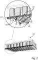
- each through-opening 106 ends in a groove 202.
- all battery cells 102 are provided with a flow path for heated gas which leads away from the plurality of battery cells 102 and where the heated gas is separated from the battery cells by the fluid filled compartment 108.
- the battery cells 102 are illustrated as cylindrical battery cells, the described battery holder and base plate may equally well be used together with battery cells having other shapes.
- the one or more grooves 202 extend across the base plate from a first edge portion of the base plate to a second edge portion of the base plate opposite the first edge portion.
- the groove 202 thereby extends across the entire base plate. It would also be possible to arrange grooves in two directions perpendicular to each other so that the grooves form a cross-shaped channel arrangement in the base plate. The grooves could thereby in principle end on all four sides if the base plate.
- additional structures for handling or guiding a gas flow are arranged adjacent to the base plate for receiving the gas flow from the end portions of the groves and for guiding a gas flow away from the battery holder.
- the illustrated grooves 202 are substantially straight but it would also be possible to for grooves which are curved, meandering or having a similar shape as long as a gas flow along the groove is not impeded.
- Fig. 3 illustrates an example battery holder 300 where the groove 202 comprises a protective coating 302.
- the external walls of the grooves 202 can be coated with a heat resistant material such as glass fiber for resistance against high temperature gases and particles coming from a cell during thermal runaway.
- the coating 302 thereby further reduces the risk of damage to adjacent battery cells in case of thermal runaway in one battery cell.
- the internal walls of the through openings 106 may advantageously be provided with the described coating.
- Fig. 4 illustrates an example battery holder 400 where an interior surface of the closed compartment comprises surface structures 402 configured to facilitate heat transfer between the base plate 104 and the fluid 110.
- the surface structures 402 increase the surface area of the internal wall of the base plate 104 forming the closed compartment 108 so that more heat can be transferred from the base plate as such to the fluid 110 when the fluid comes into contact with the internal wall comprising surface structures 402.
- the battery holder may comprise dividing walls 404 configured to form cell compartments for holding battery cells.
- the dividing walls 404 are arranged on the base plate to form a wave shape so that cylindrical battery cells can be arranged in a space efficient manner in the compartments formed by the dividing walls 404.
- the walls may also form part of an active cooling system where a coolant flows in a closed loop in the walls.
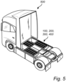
- Fig. 5 schematically illustrates a vehicle 500 comprising a battery holder 100, 200, 300, 400 according to any one of the preceding examples.
- Example 1 A battery holder (100) for holding a plurality of battery cells (102) for a vehicle, the battery holder having a base plate (104) comprising: a plurality of through openings (106), each opening being configured to allow venting of gas from a battery cell; and a closed compartment (108) being partially filled with a fluid (110).
- Example 2 The battery holder according to example 1, wherein the closed compartment extends throughout the extension of the base plate in the plane of the base plate.
- Example 3 The battery holder according to example 1, wherein the closed compartment comprises a plurality of sub-compartments, each sub-compartment being partially filled with a fluid.
- Example 4 The battery holder according to any one of the preceding examples, wherein the base plate further comprises at least one groove (202) arranged on a side of the base plate opposite the side configured to hold the battery cell and extending to at least a first edge portion (204) of the base plate, and wherein each through-opening ends in the at least one groove.
- Example 5 The battery holder according to example 4, wherein the at least one groove extends across the base plate from a first edge portion of the base plate to a second edge portion of the base plate opposite the first edge portion.
- Example 6 The battery holder according to example 4 or 5, wherein the at least one groove is substantially straight.
- Example 7 The battery holder according to any one of examples 4 to 6, wherein the at least one groove comprises a protective coating (302).
- Example 8 The battery holder according to example 7, wherein the protective coating comprises glass fiber.
- Example 9 The battery holder according to any one of the preceding examples, wherein an interior surface of the closed compartment comprises surface structures (402) configured to facilitate heat transfer between the base plate and the fluid.
- Example 10 The battery holder according to any one of the preceding examples, wherein the through openings comprise sidewalls located between the opening and the closed compartment so that the fluid is in contact with the sidewalls.
- Example 11 The battery holder according to any one of the preceding examples, wherein the fluid comprises a phase change material.
- Example 12 The battery holder according to example 11, wherein the phase change material is in solid form at a normal operating temperature of the battery.
- Example 13 The battery holder according to example 11, wherein the phase change material has a phase change temperature for transformation from solid phase to liquid phase in the range of 20°C to 30°C.
- Example 15 The battery holder according to example 11, wherein the phase change material has a phase change temperature for transformation from solid phase to liquid phase in the range of 110°C to 130°C.
- Example 16 The battery holder according to any one of the preceding examples, wherein the fluid comprises a mix of materials.
- Example 17 The battery holder according to any one of the preceding examples, wherein the fluid is selected from the group comprising dielectric oil, water glycol and water.
- Example 18 The battery holder according to any one of the preceding examples, wherein a fill level of fluid in the closed compartment is in the range of 50% to 70%.
- Example 19 The battery holder according to any one of the preceding examples, further comprising dividing walls (404) configured to form cell compartments for holding battery cells.
- Relative terms such as “below” or “above” or “upper” or “lower” or “horizontal” or “vertical” may be used herein to describe a relationship of one element to another element as illustrated in the Figures. It will be understood that these terms and those discussed above are intended to encompass different orientations of the device in addition to the orientation depicted in the Figures. It will be understood that when an element is referred to as being “connected” or “coupled” to another element, it can be directly connected or coupled to the other element, or intervening elements may be present. In contrast, when an element is referred to as being “directly connected” or “directly coupled” to another element, there are no intervening elements present.
Landscapes
- Chemical & Material Sciences (AREA)
- Chemical Kinetics & Catalysis (AREA)
- Electrochemistry (AREA)
- General Chemical & Material Sciences (AREA)
- Engineering & Computer Science (AREA)
- Manufacturing & Machinery (AREA)
- Aviation & Aerospace Engineering (AREA)
- Secondary Cells (AREA)
- Battery Mounting, Suspending (AREA)
Priority Applications (3)
| Application Number | Priority Date | Filing Date | Title |
|---|---|---|---|
| EP23202697.1A EP4539206A1 (fr) | 2023-10-10 | 2023-10-10 | Support de batterie à refroidissement par fluide |
| CN202411330042.1A CN119812433A (zh) | 2023-10-10 | 2024-09-24 | 带流体冷却的电池保持器 |
| US18/899,745 US20250118825A1 (en) | 2023-10-10 | 2024-09-27 | Battery holder with fluid cooling |
Applications Claiming Priority (1)
| Application Number | Priority Date | Filing Date | Title |
|---|---|---|---|
| EP23202697.1A EP4539206A1 (fr) | 2023-10-10 | 2023-10-10 | Support de batterie à refroidissement par fluide |
Publications (1)
| Publication Number | Publication Date |
|---|---|
| EP4539206A1 true EP4539206A1 (fr) | 2025-04-16 |
Family
ID=88315752
Family Applications (1)
| Application Number | Title | Priority Date | Filing Date |
|---|---|---|---|
| EP23202697.1A Pending EP4539206A1 (fr) | 2023-10-10 | 2023-10-10 | Support de batterie à refroidissement par fluide |
Country Status (3)
| Country | Link |
|---|---|
| US (1) | US20250118825A1 (fr) |
| EP (1) | EP4539206A1 (fr) |
| CN (1) | CN119812433A (fr) |
Citations (6)
| Publication number | Priority date | Publication date | Assignee | Title |
|---|---|---|---|---|
| US20180145382A1 (en) * | 2016-11-18 | 2018-05-24 | Romeo Systems, Inc. | Systems and methods for battery thermal management utilizing a vapor chamber |
| US20190229384A1 (en) * | 2018-01-19 | 2019-07-25 | Hanon Systems | Battery cooling plate with integrated air vents |
| DE102021106200A1 (de) * | 2021-03-15 | 2022-09-15 | Bayerische Motoren Werke Aktiengesellschaft | Kühleinrichtung mit einem Kühlkörper und Zwischenkühlelementen, elektrischer Energiespeicher sowie Kraftfahrzeug |
| US20220361367A1 (en) * | 2021-05-04 | 2022-11-10 | Rimac Automobiles Ltd. | Cold plate assembly |
| EP4156382A1 (fr) * | 2021-02-09 | 2023-03-29 | LG Energy Solution, Ltd. | Module de batterie, et bloc-batterie et véhicule le comprenant |
| WO2023186909A1 (fr) * | 2022-03-30 | 2023-10-05 | Northvolt Systems Ab | Boîtier pour module de batterie |
-
2023
- 2023-10-10 EP EP23202697.1A patent/EP4539206A1/fr active Pending
-
2024
- 2024-09-24 CN CN202411330042.1A patent/CN119812433A/zh active Pending
- 2024-09-27 US US18/899,745 patent/US20250118825A1/en active Pending
Patent Citations (6)
| Publication number | Priority date | Publication date | Assignee | Title |
|---|---|---|---|---|
| US20180145382A1 (en) * | 2016-11-18 | 2018-05-24 | Romeo Systems, Inc. | Systems and methods for battery thermal management utilizing a vapor chamber |
| US20190229384A1 (en) * | 2018-01-19 | 2019-07-25 | Hanon Systems | Battery cooling plate with integrated air vents |
| EP4156382A1 (fr) * | 2021-02-09 | 2023-03-29 | LG Energy Solution, Ltd. | Module de batterie, et bloc-batterie et véhicule le comprenant |
| DE102021106200A1 (de) * | 2021-03-15 | 2022-09-15 | Bayerische Motoren Werke Aktiengesellschaft | Kühleinrichtung mit einem Kühlkörper und Zwischenkühlelementen, elektrischer Energiespeicher sowie Kraftfahrzeug |
| US20220361367A1 (en) * | 2021-05-04 | 2022-11-10 | Rimac Automobiles Ltd. | Cold plate assembly |
| WO2023186909A1 (fr) * | 2022-03-30 | 2023-10-05 | Northvolt Systems Ab | Boîtier pour module de batterie |
Also Published As
| Publication number | Publication date |
|---|---|
| CN119812433A (zh) | 2025-04-11 |
| US20250118825A1 (en) | 2025-04-10 |
Similar Documents
| Publication | Publication Date | Title |
|---|---|---|
| KR102208720B1 (ko) | 상변화물질(pcm) 캡슐을 적용한 배터리 냉각용 히트 싱크 | |
| US20210188128A1 (en) | Thermal management structure with integrated channels | |
| US10164301B2 (en) | Energy storage thermal management system using multi-temperature phase change materials | |
| Zhao et al. | An experimental study of heat pipe thermal management system with wet cooling method for lithium ion batteries | |
| US11511648B2 (en) | Power source device and electric vehicle equipped with power source device | |
| KR101589996B1 (ko) | 액상 냉매 유출에 대한 안전성이 향상된 전지팩 | |
| US9689624B2 (en) | Method for mitigating thermal propagation of batteries using heat pipes | |
| US11990592B2 (en) | Battery, apparatus using battery, and manufacturing method and manufacturing device of battery | |
| JP2020513649A (ja) | 蒸気チャンバを利用したバッテリ熱管理のためのシステムおよび方法 | |
| JP2022185388A (ja) | 電池パック | |
| CN114667639A (zh) | 用于具有基于流体的冷却功能的牵引电池且具有带微通道的蒸发装置的壳体装置 | |
| KR20190107839A (ko) | 배터리 냉각 유닛 및 이를 포함하는 배터리 모듈 | |
| KR102308159B1 (ko) | 배터리팩 | |
| US20250118825A1 (en) | Battery holder with fluid cooling | |
| EP4557459A1 (fr) | Système de batterie refroidi par liquide | |
| US20250286213A1 (en) | Battery pack and device including the same | |
| ES3062945T3 (en) | Battery pack comprising heat transfer member having inlet and outlet for cooling fluid | |
| KR20230031058A (ko) | 차량의 배터리팩 냉각구조 | |
| US20250353348A1 (en) | Thermal management system for efficient heat dissipation | |
| KR102955774B1 (ko) | 수지 조성물 도포장치 및 배터리 어셈블리 | |
| EP4712211A1 (fr) | Bloc-batterie et véhicule le comprenant | |
| JP2026065622A (ja) | 電池パック及び電池システム | |
| KR20260052308A (ko) | 액침형 에너지 저장 장치 및 이를 포함하는 배터리 랙 | |
| KR20260056122A (ko) | 수지 조성물 도포장치 및 배터리 어셈블리 | |
| KR20220147776A (ko) | 배터리펙 열 조절기능장치 |
Legal Events
| Date | Code | Title | Description |
|---|---|---|---|
| PUAI | Public reference made under article 153(3) epc to a published international application that has entered the european phase |
Free format text: ORIGINAL CODE: 0009012 |
|
| STAA | Information on the status of an ep patent application or granted ep patent |
Free format text: STATUS: THE APPLICATION HAS BEEN PUBLISHED |
|
| AK | Designated contracting states |
Kind code of ref document: A1 Designated state(s): AL AT BE BG CH CY CZ DE DK EE ES FI FR GB GR HR HU IE IS IT LI LT LU LV MC ME MK MT NL NO PL PT RO RS SE SI SK SM TR |
|
| STAA | Information on the status of an ep patent application or granted ep patent |
Free format text: STATUS: REQUEST FOR EXAMINATION WAS MADE |
|
| STAA | Information on the status of an ep patent application or granted ep patent |
Free format text: STATUS: EXAMINATION IS IN PROGRESS |
|
| 17P | Request for examination filed |
Effective date: 20251009 |
|
| 17Q | First examination report despatched |
Effective date: 20251016 |