EP4539218A1 - Versiegelungsvorrichtung für sekundärbatterie - Google Patents
Versiegelungsvorrichtung für sekundärbatterie Download PDFInfo
- Publication number
- EP4539218A1 EP4539218A1 EP24760552.0A EP24760552A EP4539218A1 EP 4539218 A1 EP4539218 A1 EP 4539218A1 EP 24760552 A EP24760552 A EP 24760552A EP 4539218 A1 EP4539218 A1 EP 4539218A1
- Authority
- EP
- European Patent Office
- Prior art keywords
- lead
- block
- sealing
- depressed portion
- pair
- Prior art date
- Legal status (The legal status is an assumption and is not a legal conclusion. Google has not performed a legal analysis and makes no representation as to the accuracy of the status listed.)
- Pending
Links
Images



Classifications
-
- H—ELECTRICITY
- H01—ELECTRIC ELEMENTS
- H01M—PROCESSES OR MEANS, e.g. BATTERIES, FOR THE DIRECT CONVERSION OF CHEMICAL ENERGY INTO ELECTRICAL ENERGY
- H01M50/00—Constructional details or processes of manufacture of the non-active parts of electrochemical cells other than fuel cells, e.g. hybrid cells
- H01M50/10—Primary casings; Jackets or wrappings
- H01M50/102—Primary casings; Jackets or wrappings characterised by their shape or physical structure
- H01M50/105—Pouches or flexible bags
-
- B—PERFORMING OPERATIONS; TRANSPORTING
- B29—WORKING OF PLASTICS; WORKING OF SUBSTANCES IN A PLASTIC STATE IN GENERAL
- B29C—SHAPING OR JOINING OF PLASTICS; SHAPING OF MATERIAL IN A PLASTIC STATE, NOT OTHERWISE PROVIDED FOR; AFTER-TREATMENT OF THE SHAPED PRODUCTS, e.g. REPAIRING
- B29C65/00—Joining or sealing of preformed parts, e.g. welding of plastics materials; Apparatus therefor
- B29C65/02—Joining or sealing of preformed parts, e.g. welding of plastics materials; Apparatus therefor by heating, with or without pressure
-
- B—PERFORMING OPERATIONS; TRANSPORTING
- B29—WORKING OF PLASTICS; WORKING OF SUBSTANCES IN A PLASTIC STATE IN GENERAL
- B29C—SHAPING OR JOINING OF PLASTICS; SHAPING OF MATERIAL IN A PLASTIC STATE, NOT OTHERWISE PROVIDED FOR; AFTER-TREATMENT OF THE SHAPED PRODUCTS, e.g. REPAIRING
- B29C65/00—Joining or sealing of preformed parts, e.g. welding of plastics materials; Apparatus therefor
- B29C65/02—Joining or sealing of preformed parts, e.g. welding of plastics materials; Apparatus therefor by heating, with or without pressure
- B29C65/18—Joining or sealing of preformed parts, e.g. welding of plastics materials; Apparatus therefor by heating, with or without pressure using heated tools
-
- B—PERFORMING OPERATIONS; TRANSPORTING
- B29—WORKING OF PLASTICS; WORKING OF SUBSTANCES IN A PLASTIC STATE IN GENERAL
- B29C—SHAPING OR JOINING OF PLASTICS; SHAPING OF MATERIAL IN A PLASTIC STATE, NOT OTHERWISE PROVIDED FOR; AFTER-TREATMENT OF THE SHAPED PRODUCTS, e.g. REPAIRING
- B29C65/00—Joining or sealing of preformed parts, e.g. welding of plastics materials; Apparatus therefor
- B29C65/48—Joining or sealing of preformed parts, e.g. welding of plastics materials; Apparatus therefor using adhesives, i.e. using supplementary joining material; solvent bonding
-
- B—PERFORMING OPERATIONS; TRANSPORTING
- B29—WORKING OF PLASTICS; WORKING OF SUBSTANCES IN A PLASTIC STATE IN GENERAL
- B29C—SHAPING OR JOINING OF PLASTICS; SHAPING OF MATERIAL IN A PLASTIC STATE, NOT OTHERWISE PROVIDED FOR; AFTER-TREATMENT OF THE SHAPED PRODUCTS, e.g. REPAIRING
- B29C66/00—General aspects of processes or apparatus for joining preformed parts
- B29C66/01—General aspects dealing with the joint area or with the area to be joined
- B29C66/05—Particular design of joint configurations
- B29C66/10—Particular design of joint configurations particular design of the joint cross-sections
- B29C66/11—Joint cross-sections comprising a single joint-segment, i.e. one of the parts to be joined comprising a single joint-segment in the joint cross-section
- B29C66/112—Single lapped joints
- B29C66/1122—Single lap to lap joints, i.e. overlap joints
-
- B—PERFORMING OPERATIONS; TRANSPORTING
- B29—WORKING OF PLASTICS; WORKING OF SUBSTANCES IN A PLASTIC STATE IN GENERAL
- B29C—SHAPING OR JOINING OF PLASTICS; SHAPING OF MATERIAL IN A PLASTIC STATE, NOT OTHERWISE PROVIDED FOR; AFTER-TREATMENT OF THE SHAPED PRODUCTS, e.g. REPAIRING
- B29C66/00—General aspects of processes or apparatus for joining preformed parts
- B29C66/40—General aspects of joining substantially flat articles, e.g. plates, sheets or web-like materials; Making flat seams in tubular or hollow articles; Joining single elements to substantially flat surfaces
- B29C66/41—Joining substantially flat articles ; Making flat seams in tubular or hollow articles
- B29C66/43—Joining a relatively small portion of the surface of said articles
- B29C66/433—Casing-in, i.e. enclosing an element between two sheets by an outlined seam
-
- B—PERFORMING OPERATIONS; TRANSPORTING
- B29—WORKING OF PLASTICS; WORKING OF SUBSTANCES IN A PLASTIC STATE IN GENERAL
- B29C—SHAPING OR JOINING OF PLASTICS; SHAPING OF MATERIAL IN A PLASTIC STATE, NOT OTHERWISE PROVIDED FOR; AFTER-TREATMENT OF THE SHAPED PRODUCTS, e.g. REPAIRING
- B29C66/00—General aspects of processes or apparatus for joining preformed parts
- B29C66/80—General aspects of machine operations or constructions and parts thereof
- B29C66/81—General aspects of the pressing elements, i.e. the elements applying pressure on the parts to be joined in the area to be joined, e.g. the welding jaws or clamps
- B29C66/814—General aspects of the pressing elements, i.e. the elements applying pressure on the parts to be joined in the area to be joined, e.g. the welding jaws or clamps characterised by the design of the pressing elements, e.g. of the welding jaws or clamps
- B29C66/8141—General aspects of the pressing elements, i.e. the elements applying pressure on the parts to be joined in the area to be joined, e.g. the welding jaws or clamps characterised by the design of the pressing elements, e.g. of the welding jaws or clamps characterised by the surface geometry of the part of the pressing elements, e.g. welding jaws or clamps, coming into contact with the parts to be joined
- B29C66/81431—General aspects of the pressing elements, i.e. the elements applying pressure on the parts to be joined in the area to be joined, e.g. the welding jaws or clamps characterised by the design of the pressing elements, e.g. of the welding jaws or clamps characterised by the surface geometry of the part of the pressing elements, e.g. welding jaws or clamps, coming into contact with the parts to be joined comprising a single cavity, e.g. a groove
-
- B—PERFORMING OPERATIONS; TRANSPORTING
- B29—WORKING OF PLASTICS; WORKING OF SUBSTANCES IN A PLASTIC STATE IN GENERAL
- B29C—SHAPING OR JOINING OF PLASTICS; SHAPING OF MATERIAL IN A PLASTIC STATE, NOT OTHERWISE PROVIDED FOR; AFTER-TREATMENT OF THE SHAPED PRODUCTS, e.g. REPAIRING
- B29C66/00—General aspects of processes or apparatus for joining preformed parts
- B29C66/80—General aspects of machine operations or constructions and parts thereof
- B29C66/83—General aspects of machine operations or constructions and parts thereof characterised by the movement of the joining or pressing tools
- B29C66/832—Reciprocating joining or pressing tools
- B29C66/8322—Joining or pressing tools reciprocating along one axis
-
- B—PERFORMING OPERATIONS; TRANSPORTING
- B29—WORKING OF PLASTICS; WORKING OF SUBSTANCES IN A PLASTIC STATE IN GENERAL
- B29C—SHAPING OR JOINING OF PLASTICS; SHAPING OF MATERIAL IN A PLASTIC STATE, NOT OTHERWISE PROVIDED FOR; AFTER-TREATMENT OF THE SHAPED PRODUCTS, e.g. REPAIRING
- B29C66/00—General aspects of processes or apparatus for joining preformed parts
- B29C66/80—General aspects of machine operations or constructions and parts thereof
- B29C66/83—General aspects of machine operations or constructions and parts thereof characterised by the movement of the joining or pressing tools
- B29C66/832—Reciprocating joining or pressing tools
- B29C66/8322—Joining or pressing tools reciprocating along one axis
- B29C66/83221—Joining or pressing tools reciprocating along one axis cooperating reciprocating tools, each tool reciprocating along one axis
-
- B—PERFORMING OPERATIONS; TRANSPORTING
- B29—WORKING OF PLASTICS; WORKING OF SUBSTANCES IN A PLASTIC STATE IN GENERAL
- B29D—PRODUCING PARTICULAR ARTICLES FROM PLASTICS OR FROM SUBSTANCES IN A PLASTIC STATE
- B29D99/00—Subject matter not provided for in other groups of this subclass
- B29D99/006—Producing casings, e.g. accumulator cases
-
- H—ELECTRICITY
- H01—ELECTRIC ELEMENTS
- H01M—PROCESSES OR MEANS, e.g. BATTERIES, FOR THE DIRECT CONVERSION OF CHEMICAL ENERGY INTO ELECTRICAL ENERGY
- H01M50/00—Constructional details or processes of manufacture of the non-active parts of electrochemical cells other than fuel cells, e.g. hybrid cells
- H01M50/10—Primary casings; Jackets or wrappings
- H01M50/172—Arrangements of electric connectors penetrating the casing
- H01M50/174—Arrangements of electric connectors penetrating the casing adapted for the shape of the cells
- H01M50/178—Arrangements of electric connectors penetrating the casing adapted for the shape of the cells for pouch or flexible bag cells
-
- H—ELECTRICITY
- H01—ELECTRIC ELEMENTS
- H01M—PROCESSES OR MEANS, e.g. BATTERIES, FOR THE DIRECT CONVERSION OF CHEMICAL ENERGY INTO ELECTRICAL ENERGY
- H01M50/00—Constructional details or processes of manufacture of the non-active parts of electrochemical cells other than fuel cells, e.g. hybrid cells
- H01M50/10—Primary casings; Jackets or wrappings
- H01M50/183—Sealing members
-
- B—PERFORMING OPERATIONS; TRANSPORTING
- B29—WORKING OF PLASTICS; WORKING OF SUBSTANCES IN A PLASTIC STATE IN GENERAL
- B29C—SHAPING OR JOINING OF PLASTICS; SHAPING OF MATERIAL IN A PLASTIC STATE, NOT OTHERWISE PROVIDED FOR; AFTER-TREATMENT OF THE SHAPED PRODUCTS, e.g. REPAIRING
- B29C66/00—General aspects of processes or apparatus for joining preformed parts
- B29C66/80—General aspects of machine operations or constructions and parts thereof
- B29C66/82—Pressure application arrangements, e.g. transmission or actuating mechanisms for joining tools or clamps
- B29C66/824—Actuating mechanisms
- B29C66/8242—Pneumatic or hydraulic drives
-
- B—PERFORMING OPERATIONS; TRANSPORTING
- B29—WORKING OF PLASTICS; WORKING OF SUBSTANCES IN A PLASTIC STATE IN GENERAL
- B29L—INDEXING SCHEME ASSOCIATED WITH SUBCLASS B29C, RELATING TO PARTICULAR ARTICLES
- B29L2031/00—Other particular articles
- B29L2031/34—Electrical apparatus, e.g. sparking plugs or parts thereof
- B29L2031/3468—Batteries, accumulators or fuel cells
-
- B—PERFORMING OPERATIONS; TRANSPORTING
- B29—WORKING OF PLASTICS; WORKING OF SUBSTANCES IN A PLASTIC STATE IN GENERAL
- B29L—INDEXING SCHEME ASSOCIATED WITH SUBCLASS B29C, RELATING TO PARTICULAR ARTICLES
- B29L2031/00—Other particular articles
- B29L2031/712—Containers; Packaging elements or accessories, Packages
- B29L2031/7146—Battery-cases
-
- Y—GENERAL TAGGING OF NEW TECHNOLOGICAL DEVELOPMENTS; GENERAL TAGGING OF CROSS-SECTIONAL TECHNOLOGIES SPANNING OVER SEVERAL SECTIONS OF THE IPC; TECHNICAL SUBJECTS COVERED BY FORMER USPC CROSS-REFERENCE ART COLLECTIONS [XRACs] AND DIGESTS
- Y02—TECHNOLOGIES OR APPLICATIONS FOR MITIGATION OR ADAPTATION AGAINST CLIMATE CHANGE
- Y02E—REDUCTION OF GREENHOUSE GAS [GHG] EMISSIONS, RELATED TO ENERGY GENERATION, TRANSMISSION OR DISTRIBUTION
- Y02E60/00—Enabling technologies; Technologies with a potential or indirect contribution to GHG emissions mitigation
- Y02E60/10—Energy storage using batteries
Definitions
- the present invention relates to a secondary battery sealing device capable of minimizing lead damage and lead heat loss during a sealing process of a pouch-type secondary battery.
- Secondary batteries may be classified into coin-type secondary batteries, rectangular secondary batteries, cylindrical secondary batteries, and pouch-type secondary batteries, and the like, depending on the shape of the battery case.
- the pouch-type secondary battery has advantages of simple structure, high electric capacity per unit volume, low manufacturing cost, small weight, and easy shape change. Accordingly, recently, the pouch-type secondary batteries in which aluminum pouches are packaged in battery cells laminated with electrodes and separators have been widely used.
- the pouch-type secondary battery is formed by performing slurry mixing, electrode (positive electrode material/negative electrode material) coating, electrode plate pressing, electrode plate slitting and electrode plate punching/notching, electrode plate drying, electrode plate lamination, electrode plate stacking, pouch packaging, electrolyte injection, formation, and pouch degassing processes in this order.
- an electrode assembly in which electrodes and separators are alternately laminated is packaged with a pouch, and when packaging the pouch, a pair of leads electrically connected to the electrodes of the electrode assembly is exposed to the outside of the pouch.
- the packaging process comprises a sealing process for bonding of the pouch and the lead through a lead film.
- Figures 1 and 2 are diagrams for explaining conventional secondary battery sealing device and lead block
- Figure 3 is a diagram for explaining a state where a lead of a battery cell is placed on the lead block shown in Figure 1
- Figure 4 is a diagram for explaining positions of a battery cell, a pair of sealing blocks, and a pair of lead blocks when a sealing process is performed using the conventional secondary battery sealing device shown in Figure 3 .
- the conventional secondary battery sealing device (1) comprises a main body (2), a pair of sealing blocks (10) provided on the main body (2) and for bonding a sealing target region of a battery cell (3), and a pair of lead blocks (20) provided on the pair of sealing blocks (10), respectively, and seated by the lead (4) of the battery cell (3) exposed to the outside of the pouch.
- a first sealing block (12) supporting the lower side of the battery cell (3) and seated by the battery cell (3), and a first lead block (22) provided on the first sealing block (12) so that the lead (4) of the battery cell (3) is seated are located on the lower side of the battery cell (3).
- the heat applied to the first sealing block (12) and the second sealing block (14) is used to melt a sealant coated on a lead film (5) and the pouch (not shown), thereby sealing the lead (4) and the pouch.
- the lead film (5) made of a polypropylene material (PP) does not melt properly by the heat of the first sealing block (12) and the second sealing block (14) alone.
- heating members are also provided on the first sealing block (12) and the second sealing block (14), as well as the first lead block (22) and the second lead block (24), and heat is applied to the first lead block (22) and the second lead block (24).
- the lead (4) disposed between the first lead block (22) and the second lead block (24) and the lead film connected to the lead (4) also have a certain degree of heat.
- the lead film (5) is well melted by the first sealing block (12), the second sealing block (14), and the first lead block (22) and the second lead block (24), so that it can be easy to seal the lead (4) and the pouch.
- the lead (4) seated on the opposing surface (23) of the first lead block (23) having one flat surface is in contact with the opposing surface (23) of the first lead block (22) and the opposing surface (25) of the second lead block (24), respectively.
- the opposing surface (23) of the first lead block (22) and the opposing surface (25) of the second lead block (24) have a flat surface, so that the area in contact with the lead (4) increases, and there is a problem that damage such as scratches occurs on the outer surface of the lead (4).
- first lead block (22) and the second lead block (24) are not in direct contact with the lead (4), such as a method of wrapping an insulating tape around each of the first lead block (22) and the second lead block (24), has been used.
- a secondary battery sealing device as a sealing device for bonding a pouch and a lead film of a battery cell, in which it comprises a pair of sealing blocks seated by a battery cell, and provided to pressurize bonding target regions of a pouch and a lead film of the seated battery cell, and a pair of lead blocks seated by the lead of the battery cell exposed to the outside of the pouch, and provided to cover the seated lead, wherein at least one lead block of the pair of lead blocks is provided with a recess part for receiving the lead.
- the pair of lead blocks may be provided so that the regions excluding the depressed portion are in contact with each other along the edge of the lead.
- the width of the depressed portion may be more than or equal to the width of the lead.
- the depth of the depressed portion may be more than or equal to the thickness of the lead.
- each lead block may be provided to cover the seated lead when the pair of sealing blocks pressurizes the bonding target regions in a state where the lead is seated.
- each lead block may be provided on the pair of sealing blocks, respectively, and may be provided to be movable together with each sealing block.
- the pair of lead blocks when the lead is received in the depressed portion by the pair of lead blocks, the pair of lead blocks may be provided to be in surface contact with each other in at least some regions along the edge of the lead, excluding the region where the depressed portion is formed.
- the depressed portion may form a receiving space for the reed, and by confining heat within the receiving space, the heat of the reed may be prevented from being lost to the outside.
- the pair of sealing blocks may comprise a first sealing block supporting the lower side of the battery cell so that the battery cell is seated, and a second sealing block pressurizing the battery cell seated on the first sealing block as it moves toward the first sealing block.
- the pair of lead blocks may comprise a first lead block coupled to the first sealing block so that the lead is seated when the battery cell is seated on the first sealing block, and a second lead block provided to cover the lead seated on the first lead block as the second sealing block moves toward the first sealing block.
- the depressed portion may be provided in the first lead block.
- the width of the depressed portion may be more than or equal to the width of the lead.
- the depth of the depressed portion may be more than or equal to the thickness of the lead.
- the respective opposing surfaces of the first lead block and the second lead block may be provided to be in surface contact with each other along the edge of the lead, excluding the region where the depressed portion is formed.
- the lead and the lead film exposed to one open surface of the depressed portion may be pressurized by the first and second sealing blocks.
- the depressed portion When the lead is covered by the second lead block, the depressed portion may have a structure in which one surface facing the pouch is open.
- the depressed portion may be provided in each of the first lead block and the second lead block.
- the total depth of the depressed portion formed in each lead block may be more than or equal to the thickness of the lead.
- the secondary battery sealing device related to one example of the present invention has the following effects.
- the lead of the battery cell exposed to the outside of the pouch is covered, in a state of being inserted into the depressed portion formed in any one of the pair of lead blocks, by the other lead block. Accordingly, the portion of the lead exposed to the atmosphere is minimized, so that the heat loss from the lead can be minimized.
- the lead is inserted into the depressed portion of any one lead block and then covered by the other lead block, so that the area in contact with the pair of lead blocks can be minimized, and appearance damage, such as scratches, of the lead can be reduced by the pair of lead blocks.
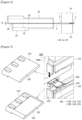
- Figure 5 is diagrams enlarging and showing a secondary battery sealing device (100) and a lead block according to one example of the present invention
- Figure 6 is a diagram showing a battery cell (101) sealed by the secondary battery sealing device according to one example of the present invention shown in Figure 5 .
- the secondary battery sealing device (100) may be used during a pouch packaging process performed between an electrode plate stacking process and an electrolyte injection process among the processes of manufacturing a pouch-type secondary battery.
- the secondary battery sealing device (100) is used in a sealing process for bonding a preset bonding target region (S) between the pouch (104) and the lead (102) of the battery cell (101) through the lead film (103) of the battery cell (101).
- Figure 7 is a diagram for explaining positions of a battery cell, a pair of sealing blocks, and a pair of lead blocks when a sealing process is performed by the secondary battery sealing device shown in Figure 5 ;
- Figure 8 is a diagram showing a lead of a battery cell;
- Figure 9 is a diagram showing a first lead block.
- the pair of sealing blocks (110) is a part for thermally pressurizing the battery cell (101), which performs a function of thermally pressurizing the bonding target region (S) to seal the bonding target region (S).
- At least one of the pair of lead blocks (120) is provided with a depressed portion (121) for receiving the lead (102).
- the pair of sealing blocks (110) thermally pressurizes a preset bonding target region (S) between the pouch (104) and the lead (102) through the lead film (103).
- the pair of sealing blocks (110) may comprise a first sealing block (112) and a second sealing block (114).
- the first sealing block (112) and the second sealing block (114) may be provided at a predetermined interval from each other in the vertical direction of the main body (100a) of the secondary battery sealing device (100).
- a driving part (170) such as a cylinder, is connected to at least one of the first sealing block (112) and the second sealing block (114), which may be provided to be capable of ascending and descending within the main body (100a1).
- the driving part (170) the interval between the first sealing block (112) and the second sealing block (114) may be adjusted, and when the bonding target region (S) is pressurized, at least one of the first sealing block (112) and the second sealing block (114) is moved in a direction closer to each other, and the interval between the first sealing block (112) and the second sealing block (114) becomes smaller.
- the first sealing block (112) and the second sealing block (114) pressurize a preset bonding target region (S) on the battery cell (101).
- the battery cell (101) is seated on the first sealing block (112).
- the lower surface of the bonding target region (S) of the battery cell (101) is seated on the first sealing block (112).
- the second sealing block (114) pressurizes the upper surface of the battery cell (101) seated on the first sealing block (112). Specifically, the second sealing block (114) pressurizes the upper surface of the bonding region (S) of the battery cell (101) seated on the first sealing block (112).
- the second sealing block (114) may descend in a direction closer to the first sealing block (112) to pressurize the battery cell (101) seated on the first sealing block (112).
- the second sealing block (114) and the first sealing block (112) may pressurize the bonding target region (S) of the battery cell (101) and simultaneously transfer heat to the bonding target region (S).
- first sealing block (112) and the second sealing block (114) may be connected to heating members (161, 162), such as heaters, respectively. Accordingly, the first sealing block (112) and the second sealing block (114) receive heat from the connected heating members (161, 162), respectively, thereby thermally pressurizing the bonding target region (S) of the battery cell (101).
- the heating members (161, 162) may also be disposed inside each of the sealing blocks (112, 114), and may also be attached to one surface of the sealing blocks (112, 114).
- a pair of lead blocks (120) may be provided on the first sealing block (112) and the second sealing block (114), respectively.
- the pair of lead blocks (120) are portions for supporting the lead (102) of the battery cell (10) exposed to the outside of the pouch (104).
- the pair of lead blocks (120) may comprise a first lead block (122) and a second lead block (124).
- the first lead block (122) may be provided on the first sealing block (112).
- the first lead block (122) may be formed integrally with the first sealing block (112), and the first lead block (122) may be connected to the first sealing block (112) at a predetermined interval.
- the lead (102) of the battery cell (101) seated on the first sealing block (112) is seated on the first lead block (122).
- the lower surface of the bonding target region (S) of the battery cell (101) is seated on the first sealing block (112)
- the lower surface of the lead (102) may be seated on the first lead block (122).
- a depressed portion (121) for receiving the lead (102) may be formed on the opposing surface (123) of the first lead block (122) facing the second lead block (124).
- the second lead block (124) may be provided on the second sealing block (114) to face the first lead block (122).
- the second lead block (124) may be formed integrally with the second sealing block (114), and the second lead block (124) may be connected to the second sealing block (114) at a predetermined interval.
- the entire opposing surface (125) of the second lead block (124) may be formed to be flat.
- the second lead block (124) covers the lead (102) seated on the first lead block (122). Specifically, when the second sealing block (114) pressurizes the upper surface of the bonding target region (S) of the battery cell (101), the second lead block (124) surrounds the upper surface of the lead (102).
- the region of the opposing surface (123) of the first lead block (122) except for the depressed portion (121) may be in surface contact with the opposing surface (125) of the second lead block (124) from each other along the edge.
- the depressed portion (121) of the first lead block (122) may be formed to be depressed inward with respect to the opposing surface (121) of the first lead block (122). Therefore, the opposing surface (123) of the first lead block (122) has a step between the edge regions of the depressed portion (121).
- the depressed portion (121) may be formed only in some regions of the first lead block (122).
- the depressed portion (121) may also be formed in the entire region of the first lead block (122), but to minimize the portion of the lead (102) covered by the first lead block (122) and the second lead block (124) exposed to the atmosphere, it is preferable that the depressed portion (121) is formed only in some regions (e.g., the central region) of the opposing surface (123) excluding the edge.
- the width (L2) of the depressed portion (121) may be formed to be more than or equal to the width (L1) of the lead (102).
- the width (L2) of the depressed portion (121) may be formed to be larger than the width (L1) of the lead (102) exposed to the outside of the pouch.
- the width (L2) of the depressed portion (121) may be formed to be larger than the width (L1) of the lead (102) by about 2mm to 4mm or so, but is not necessarily limited thereto.
- the depth (D2) of the depressed portion (121) may be formed to be more than or equal to the thickness (D1) of the lead (102).
- the depth (D2) of the depressed portion (121) may be formed to be larger than the thickness (D1) of the lead (102) exposed to the outside of the pouch.
- the bonding target region (S) between the lead film (103) and the connection portion (102c) of the lead (102) exposed from the first lead block (122) and the second lead block (124) is thermally pressurized by the first sealing block (112) and the second sealing block (114), and sealed.
- the depressed portion (121) for receiving the lead (102) is formed in the first lead block (122)
- the present invention is not limited thereto, and the depressed portion may be provided on the first lead block and the second lead block, respectively.
- the depressed portion (also referred to as 'first depressed portion') formed in the first lead block and the depressed portion (also referred to as 'second depressed portion') formed in the second lead block may also form together the receiving space for the lead (102).
- the total depth of the depressed portion formed in each lead block (122, 124) may be more than or equal to the thickness of the lead.
- the thickness of the first depressed portion may be 1/2 or more of the thickness of the lead
- the thickness of the second depressed portion may be 1/2 or more of the thickness of the lead.
Landscapes
- Engineering & Computer Science (AREA)
- Mechanical Engineering (AREA)
- Chemical & Material Sciences (AREA)
- Chemical Kinetics & Catalysis (AREA)
- Electrochemistry (AREA)
- General Chemical & Material Sciences (AREA)
- Sealing Battery Cases Or Jackets (AREA)
- Connection Of Batteries Or Terminals (AREA)
- Secondary Cells (AREA)
Applications Claiming Priority (2)
| Application Number | Priority Date | Filing Date | Title |
|---|---|---|---|
| KR20230022551 | 2023-02-21 | ||
| PCT/KR2024/002207 WO2024177363A1 (ko) | 2023-02-21 | 2024-02-21 | 이차전지 실링장치 |
Publications (2)
| Publication Number | Publication Date |
|---|---|
| EP4539218A1 true EP4539218A1 (de) | 2025-04-16 |
| EP4539218A4 EP4539218A4 (de) | 2025-09-03 |
Family
ID=92501471
Family Applications (1)
| Application Number | Title | Priority Date | Filing Date |
|---|---|---|---|
| EP24760552.0A Pending EP4539218A4 (de) | 2023-02-21 | 2024-02-21 | Versiegelungsvorrichtung für sekundärbatterie |
Country Status (5)
| Country | Link |
|---|---|
| EP (1) | EP4539218A4 (de) |
| JP (1) | JP2025524670A (de) |
| KR (1) | KR20240130045A (de) |
| CN (1) | CN119522504A (de) |
| WO (1) | WO2024177363A1 (de) |
Family Cites Families (12)
| Publication number | Priority date | Publication date | Assignee | Title |
|---|---|---|---|---|
| JP5042402B2 (ja) * | 2000-02-16 | 2012-10-03 | 大日本印刷株式会社 | ポリマー電池包装用シールヘッド |
| JP2006099970A (ja) * | 2004-09-28 | 2006-04-13 | Nec Tokin Tochigi Ltd | 引出端子部の封口方法および封口装置 |
| JP5082263B2 (ja) * | 2006-03-10 | 2012-11-28 | 日本電気株式会社 | フィルム外装電気デバイスの製造方法 |
| KR20120126932A (ko) * | 2011-05-13 | 2012-11-21 | 에스케이이노베이션 주식회사 | 파우치형 이차전지의 실링방법 및 실링장치 |
| JP2013196930A (ja) * | 2012-03-21 | 2013-09-30 | Aisin Seiki Co Ltd | 蓄電デバイス及び蓄電デバイスの封止方法 |
| KR20150071918A (ko) * | 2013-12-19 | 2015-06-29 | 주식회사 엘지화학 | 이차전지의 실링장치 및 실링방법 |
| WO2016159607A1 (ko) * | 2015-04-02 | 2016-10-06 | 주식회사 엘지화학 | 파우치형 이차전지의 실링 장치 |
| KR101852250B1 (ko) * | 2015-04-02 | 2018-04-26 | 주식회사 엘지화학 | 파우치형 이차전지의 실링 장치 |
| KR102077273B1 (ko) * | 2015-12-15 | 2020-02-13 | 주식회사 엘지화학 | 파우치형 이차 전지의 테라스 성형 장치 |
| CN106784998B (zh) * | 2017-01-22 | 2024-10-15 | 宁德新能源科技有限公司 | 一种二次电池及加热装置 |
| KR102793092B1 (ko) * | 2019-11-13 | 2025-04-08 | 주식회사 엘지에너지솔루션 | 이차 전지 및 실링 블록 |
| KR102569687B1 (ko) | 2021-08-09 | 2023-08-25 | 주식회사 플레이칸 | 애니메이션 제작 방법 및 시스템 |
-
2024
- 2024-02-21 EP EP24760552.0A patent/EP4539218A4/de active Pending
- 2024-02-21 WO PCT/KR2024/002207 patent/WO2024177363A1/ko not_active Ceased
- 2024-02-21 CN CN202480003337.XA patent/CN119522504A/zh active Pending
- 2024-02-21 KR KR1020240024787A patent/KR20240130045A/ko active Pending
- 2024-02-21 JP JP2025502346A patent/JP2025524670A/ja active Pending
Also Published As
| Publication number | Publication date |
|---|---|
| JP2025524670A (ja) | 2025-07-30 |
| CN119522504A (zh) | 2025-02-25 |
| EP4539218A4 (de) | 2025-09-03 |
| KR20240130045A (ko) | 2024-08-28 |
| WO2024177363A1 (ko) | 2024-08-29 |
Similar Documents
| Publication | Publication Date | Title |
|---|---|---|
| JP6884795B2 (ja) | 折り畳まれた封止部を有する段差型電気化学セル | |
| EP2012376B1 (de) | Sekundärbatterie | |
| EP3249732B1 (de) | Versiegelungsvorrichtung eines pouch-akkumulators | |
| KR20190042800A (ko) | 균열 방지 구조를 포함하는 파우치형 전지케이스 및 이의 제조방법 | |
| EP3800690B1 (de) | Sekundärbatterie | |
| KR20190042801A (ko) | 균열을 방지하기 위한 파우치형 이차전지용 실링 블록, 이를 사용하여 제조되는 파우치형 전지케이스 및 파우치형 전지케이스의 실링 방법 | |
| US11050103B2 (en) | Pouch cell and method of forming same | |
| KR20190092017A (ko) | 파우치 성형 장치 및 방법 | |
| US20200185668A1 (en) | Deep Pouch Cell and Method of Manufacturing Same | |
| EP4300647A1 (de) | Elektrodenanordnung und batteriezelle damit | |
| KR20230078926A (ko) | 전극 단자의 리벳팅 구조 및 이를 포함하는 배터리 셀, 배터리 팩 및 자동차 | |
| KR101185056B1 (ko) | 이차 전지 | |
| EP4261016A1 (de) | Beutelbatterie und dichtungsvorrichtung für beutelbatterie | |
| EP4539218A1 (de) | Versiegelungsvorrichtung für sekundärbatterie | |
| US20240429571A1 (en) | Secondary battery | |
| KR20180034903A (ko) | 수납부 및 전극 리드용 그루브를 포함하는 전지케이스를 구비한 전지셀 | |
| KR102238177B1 (ko) | 전지셀 및 전극 리드 제조방법 | |
| CN113904035B (zh) | 一种电芯、电池模组及用电设备 | |
| EP4250467A1 (de) | Sekundärbatterie und herstellungsverfahren dafür | |
| KR100858789B1 (ko) | 분리막의 열융착에 의해 형성된 댐핑부를 포함하고 있는향상된 안전성의 전기화학 셀 | |
| KR101308242B1 (ko) | 파우치형 이차전지 | |
| KR102082655B1 (ko) | 모서리가 절취되어 있는 구조의 전극조립체 제조방법 및 이를 사용하여 제조되는 전극조립체 | |
| EP4726833A1 (de) | Sekundärbatteriepressvorrichtung und sekundärbatteriepressverfahren damit | |
| KR20160130588A (ko) | 높이 조절이 가능한 미실링부를 포함하는 전지케이스용 실링 장치 | |
| KR20240064438A (ko) | 파우치 및 이를 포함하는 파우치 셀 제조 방법 |
Legal Events
| Date | Code | Title | Description |
|---|---|---|---|
| STAA | Information on the status of an ep patent application or granted ep patent |
Free format text: STATUS: THE INTERNATIONAL PUBLICATION HAS BEEN MADE |
|
| PUAI | Public reference made under article 153(3) epc to a published international application that has entered the european phase |
Free format text: ORIGINAL CODE: 0009012 |
|
| STAA | Information on the status of an ep patent application or granted ep patent |
Free format text: STATUS: REQUEST FOR EXAMINATION WAS MADE |
|
| 17P | Request for examination filed |
Effective date: 20250113 |
|
| AK | Designated contracting states |
Kind code of ref document: A1 Designated state(s): AL AT BE BG CH CY CZ DE DK EE ES FI FR GB GR HR HU IE IS IT LI LT LU LV MC ME MK MT NL NO PL PT RO RS SE SI SK SM TR |
|
| A4 | Supplementary search report drawn up and despatched |
Effective date: 20250805 |
|
| RIC1 | Information provided on ipc code assigned before grant |
Ipc: H01M 50/183 20210101AFI20250730BHEP Ipc: H01M 50/557 20210101ALI20250730BHEP Ipc: H01M 50/105 20210101ALI20250730BHEP Ipc: B29C 65/00 20060101ALI20250730BHEP Ipc: B29C 65/18 20060101ALI20250730BHEP Ipc: H01M 50/178 20210101ALI20250730BHEP |
|
| GRAP | Despatch of communication of intention to grant a patent |
Free format text: ORIGINAL CODE: EPIDOSNIGR1 |
|
| STAA | Information on the status of an ep patent application or granted ep patent |
Free format text: STATUS: GRANT OF PATENT IS INTENDED |