EP4539304A1 - Elektrische drehmaschine - Google Patents
Elektrische drehmaschine Download PDFInfo
- Publication number
- EP4539304A1 EP4539304A1 EP22945811.2A EP22945811A EP4539304A1 EP 4539304 A1 EP4539304 A1 EP 4539304A1 EP 22945811 A EP22945811 A EP 22945811A EP 4539304 A1 EP4539304 A1 EP 4539304A1
- Authority
- EP
- European Patent Office
- Prior art keywords
- layer
- magnet
- hole portion
- electric machine
- rotary electric
- Prior art date
- Legal status (The legal status is an assumption and is not a legal conclusion. Google has not performed a legal analysis and makes no representation as to the accuracy of the status listed.)
- Pending
Links
Images


Classifications
-
- H—ELECTRICITY
- H02—GENERATION; CONVERSION OR DISTRIBUTION OF ELECTRIC POWER
- H02K—DYNAMO-ELECTRIC MACHINES
- H02K1/00—Details of the magnetic circuit
- H02K1/06—Details of the magnetic circuit characterised by the shape, form or construction
- H02K1/22—Rotating parts of the magnetic circuit
- H02K1/27—Rotor cores with permanent magnets
- H02K1/2706—Inner rotors
- H02K1/272—Inner rotors the magnetisation axis of the magnets being perpendicular to the rotor axis
- H02K1/274—Inner rotors the magnetisation axis of the magnets being perpendicular to the rotor axis the rotor consisting of two or more circumferentially positioned magnets
- H02K1/2753—Inner rotors the magnetisation axis of the magnets being perpendicular to the rotor axis the rotor consisting of two or more circumferentially positioned magnets the rotor consisting of magnets or groups of magnets arranged with alternating polarity
- H02K1/276—Magnets embedded in the magnetic core, e.g. interior permanent magnets [IPM]
- H02K1/2766—Magnets embedded in the magnetic core, e.g. interior permanent magnets [IPM] having a flux concentration effect
-
- H—ELECTRICITY
- H02—GENERATION; CONVERSION OR DISTRIBUTION OF ELECTRIC POWER
- H02K—DYNAMO-ELECTRIC MACHINES
- H02K1/00—Details of the magnetic circuit
- H02K1/06—Details of the magnetic circuit characterised by the shape, form or construction
- H02K1/22—Rotating parts of the magnetic circuit
- H02K1/27—Rotor cores with permanent magnets
- H02K1/2706—Inner rotors
- H02K1/272—Inner rotors the magnetisation axis of the magnets being perpendicular to the rotor axis
- H02K1/274—Inner rotors the magnetisation axis of the magnets being perpendicular to the rotor axis the rotor consisting of two or more circumferentially positioned magnets
- H02K1/2753—Inner rotors the magnetisation axis of the magnets being perpendicular to the rotor axis the rotor consisting of two or more circumferentially positioned magnets the rotor consisting of magnets or groups of magnets arranged with alternating polarity
- H02K1/276—Magnets embedded in the magnetic core, e.g. interior permanent magnets [IPM]
-
- H—ELECTRICITY
- H02—GENERATION; CONVERSION OR DISTRIBUTION OF ELECTRIC POWER
- H02K—DYNAMO-ELECTRIC MACHINES
- H02K2213/00—Specific aspects, not otherwise provided for and not covered by codes H02K2201/00 - H02K2211/00
- H02K2213/03—Machines characterised by numerical values, ranges, mathematical expressions or similar information
Definitions
- the present invention relates to a rotary electric machine.
- stress of a rotor core which is generated by a rotational centrifugal force of a rotor, varies depending on the shape of a magnet hole of the rotor core.
- the maximum main stress needs to be equal to or less than the material strength of the material amount of the rotor core.
- the torque is improved in a configuration of the magnet arranged in a double V-shape as compared with a configuration of the magnet arranged in a single V-shape, and thus, it is advantageous to adopt the latter in order to improve the performance, but the stress of the rotor core increases. Based on this, the rotor core is required to achieve both improvement in torque and response to stress.
- PTL 1 below discloses a configuration of a permanent magnet motor in which a double V-shaped magnet is arranged and a hole is provided in a portion other than a magnet insertion portion to disperse stress of a rotor core, which is generated by a centrifugal force.
- an object of the present invention is to provide a rotary electric machine that reduces stress without reducing torque and improves rotational strength.
- a rotary electric machine includes a rotor core having a plurality of magnet holes, and a plurality of magnets respectively inserted into the plurality of magnet holes.
- the magnet includes a pair of first layer magnets arranged in a V-shape and a pair of second layer magnets arranged in a V-shape on an inner diameter side of the first layer magnets, and the rotor core has a hole portion at a position that overlaps with a d-axis which is a magnetic pole center of the rotor core, the hole portion being between the first layer magnet and the second layer magnet.
- Positions, sizes, shapes, ranges, and the like of components illustrated in the drawings may not represent actual positions, actual sizes, actual shapes, actual ranges, and the like in order to facilitate understanding of the invention. Therefore, the present invention is not necessarily limited to the positions, the sizes, the shapes, the ranges, and the like disclosed in the drawings.
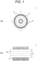
- FIG. 1(a) is a view of a rotary electric machine as viewed from an axial direction.
- FIG. 1(b) is a view of FIG. 1(a) as viewed from a radial direction.
- a rotary electric machine 1 includes a stator 2 on an outer peripheral side and a rotor 3 on an inner peripheral side. The rotor 3 faces the stator 2 with a predetermined gap (not shown) interposed therebetween.
- a stator core 2a is an electromagnetic steel plate having a plurality of slots.
- a plurality of coils 6 are arranged side by side in the radial direction and inserted into the plurality of slots provided in the stator core 2a.
- the rotor core 4 (referred to as a core 4 below) of the rotor 3 has a plurality of holes.
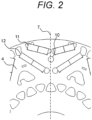
- magnet holes into which a plurality of magnets are respectively inserted include magnet holes into which a pair of first layer magnets 11 arranged in a V-shape are inserted, and magnet holes into which a pair of second layer magnets 12 arranged in a V-shape on an inner diameter side of the first layer magnets 11 are inserted.
- the core 4 has a hole portion 10 at a position that overlaps with a d-axis 7, which is the magnetic pole center of the rotor core 4, between the first layer magnet 11 and the second layer magnet 12.
- the hole portion 10 is a hole for reducing stress.
- the hole portion 10 is not provided in a portion in which the density of the magnetic flux is high in the core 4, that is, on a flow path of the magnetic flux, and is provided at a position at which the magnetic performance is not affected.
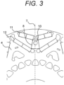
- FIG. 3 (FIG. 3)
- the hole portion 10 is disposed in a region 8 formed by joining the corner on the innermost diameter side among the corners of the first layer magnets 11 and the corner closest to the d-axis 7 among the corners of the second layer magnets 12. As described above, by providing the hole portion 10 in the region 8 at the position that overlaps with the d-axis 7 between the first layer magnet hole and the second layer magnet hole, it is possible to disperse and reduce a load of stress related to the d-axis 7 on the inner side and the outer side of the core 4 in a well-balanced manner, so that it is possible to realize the stress reduction and the improvement of the rotational strength of the core 4.
- a plurality of hole portions 10 may be formed in the core 4 as long as a configuration in which the hole portions 10 are provided at positions that overlap with the d-axis 7 between the first layer magnet 11 and the second layer magnet 12, and the hole portions 10 are formed as voids is made.
- FIG. 4 (FIG. 4)
- a hole portion 10a includes a lower side that has a predetermined curvature and protrudes inward in the radial direction, and an upper side that has a curvature smaller than the predetermined curvature and protrudes outward in the radial direction.
- FIG. 5 (FIG. 5)
- a hole portion 10b includes a lower side that has a predetermined curvature and protrudes inward in the radial direction, and an upper side that has a curvature larger than the predetermined curvature and protrudes outward in the radial direction.
- the area of the hole portion 10 described with reference to FIGS. 2 and 3 is the same as the areas of the hole portions 10a and 10b described with reference to FIGS. 4 and 5 .
- the shape of the hole portion 10 does not need to be limited as long as the hole portion is provided at a place of the core 4 that does not affect the flow path of the magnetic flux and the size thereof does not affect the flow path of the magnetic flux.
- FIG. 6 (FIG. 6)
- the maximum diameter dimension d1 of the hole portion 10 is larger than the bridge width d2 formed between a pair of magnet holes into which the second layer magnets 12 are respectively inserted.
- FIG. 6 illustrates the maximum diameter dimension d1 in a direction perpendicular to the d-axis 7 in order to facilitate comparison of the width dimension.
- FIG. 7 (FIG. 7)
- a first angle ⁇ 1 formed by the first layer magnet 11 and the d-axis 7 is larger than a second angle ⁇ 2 formed by the second layer magnet 12 and the d-axis 7.
- the present invention is not limited to the above embodiment, and various modifications and other configurations can be combined without departing from the gist of the present invention.
- the present invention is not limited to one including all the configurations described in the above embodiment, and includes one in which a portion of the configuration is deleted.
Landscapes
- Engineering & Computer Science (AREA)
- Power Engineering (AREA)
- Permanent Field Magnets Of Synchronous Machinery (AREA)
Applications Claiming Priority (1)
| Application Number | Priority Date | Filing Date | Title |
|---|---|---|---|
| PCT/JP2022/023237 WO2023238309A1 (ja) | 2022-06-09 | 2022-06-09 | 回転電機 |
Publications (2)
| Publication Number | Publication Date |
|---|---|
| EP4539304A1 true EP4539304A1 (de) | 2025-04-16 |
| EP4539304A4 EP4539304A4 (de) | 2026-04-01 |
Family
ID=89117760
Family Applications (1)
| Application Number | Title | Priority Date | Filing Date |
|---|---|---|---|
| EP22945811.2A Pending EP4539304A4 (de) | 2022-06-09 | 2022-06-09 | Elektrische drehmaschine |
Country Status (5)
| Country | Link |
|---|---|
| US (1) | US20250233467A1 (de) |
| EP (1) | EP4539304A4 (de) |
| JP (1) | JPWO2023238309A1 (de) |
| CN (1) | CN118891806A (de) |
| WO (1) | WO2023238309A1 (de) |
Family Cites Families (6)
| Publication number | Priority date | Publication date | Assignee | Title |
|---|---|---|---|---|
| JP5353962B2 (ja) * | 2011-07-05 | 2013-11-27 | 日産自動車株式会社 | 永久磁石型電動機 |
| JP6331506B2 (ja) * | 2014-03-12 | 2018-05-30 | 日産自動車株式会社 | 回転電機のロータ構造 |
| EP3261220B1 (de) * | 2016-06-23 | 2020-08-12 | Volvo Car Corporation | Elektrische maschine |
| JP6508168B2 (ja) * | 2016-11-15 | 2019-05-08 | トヨタ自動車株式会社 | 回転電機 |
| CN108321951B (zh) * | 2018-03-16 | 2019-12-27 | 珠海格力电器股份有限公司 | 转子结构、永磁辅助同步磁阻电机及电动汽车 |
| DE102018204299A1 (de) * | 2018-03-21 | 2019-09-26 | Zf Friedrichshafen Ag | Rotor einer permanentmagneterregten elektrischen Maschine |
-
2022
- 2022-06-09 JP JP2024526139A patent/JPWO2023238309A1/ja active Pending
- 2022-06-09 US US18/848,774 patent/US20250233467A1/en active Pending
- 2022-06-09 CN CN202280093832.5A patent/CN118891806A/zh active Pending
- 2022-06-09 EP EP22945811.2A patent/EP4539304A4/de active Pending
- 2022-06-09 WO PCT/JP2022/023237 patent/WO2023238309A1/ja not_active Ceased
Also Published As
| Publication number | Publication date |
|---|---|
| JPWO2023238309A1 (de) | 2023-12-14 |
| US20250233467A1 (en) | 2025-07-17 |
| CN118891806A (zh) | 2024-11-01 |
| WO2023238309A1 (ja) | 2023-12-14 |
| EP4539304A4 (de) | 2026-04-01 |
Similar Documents
| Publication | Publication Date | Title |
|---|---|---|
| US10594177B2 (en) | Rotary electric machine and rotor core manufacturing method | |
| CN102629790B (zh) | 用于旋转电机的转子 | |
| JP6507273B2 (ja) | 永久磁石埋込型電動機のためのロータ及びそれを用いた電動機 | |
| JP2012161228A (ja) | 回転電機用回転子 | |
| CN105814773B (zh) | 永磁铁埋入型电动机 | |
| US12519353B2 (en) | Rotor core with plurality of permanent magnets and magnet holes with bridges between magnets/magnet holes | |
| US7474028B2 (en) | Motor | |
| JP2020068535A (ja) | ロータ | |
| KR20180090476A (ko) | 모터 | |
| US20190372411A1 (en) | Rotor and motor using same | |
| CN102810917A (zh) | 开关磁阻电机 | |
| JP2011147346A (ja) | 電動機 | |
| EP4539304A1 (de) | Elektrische drehmaschine | |
| JP7126557B2 (ja) | 回転電機 | |
| CN106063085B (zh) | 转子 | |
| US11146128B1 (en) | Squirrel-cage rotor and rotating electric machine | |
| EP4167450A1 (de) | Elektromotor | |
| US20250309709A1 (en) | Rotor for rotating electrical machine | |
| US20250364856A1 (en) | Rotating Electrical Machine | |
| CN204290538U (zh) | 永久磁铁埋入式电动机 | |
| JP7593433B2 (ja) | 電動機 | |
| JP7574875B2 (ja) | 電動機 | |
| WO2019044612A1 (ja) | 電動モータ | |
| WO2018159349A1 (ja) | モータ、動力装置、及びブルドーザ | |
| KR102159798B1 (ko) | 아우터 로터 타입의 모터 |
Legal Events
| Date | Code | Title | Description |
|---|---|---|---|
| STAA | Information on the status of an ep patent application or granted ep patent |
Free format text: STATUS: THE INTERNATIONAL PUBLICATION HAS BEEN MADE |
|
| PUAI | Public reference made under article 153(3) epc to a published international application that has entered the european phase |
Free format text: ORIGINAL CODE: 0009012 |
|
| STAA | Information on the status of an ep patent application or granted ep patent |
Free format text: STATUS: REQUEST FOR EXAMINATION WAS MADE |
|
| 17P | Request for examination filed |
Effective date: 20250109 |
|
| AK | Designated contracting states |
Kind code of ref document: A1 Designated state(s): AL AT BE BG CH CY CZ DE DK EE ES FI FR GB GR HR HU IE IS IT LI LT LU LV MC MK MT NL NO PL PT RO RS SE SI SK SM TR |
|
| RAP3 | Party data changed (applicant data changed or rights of an application transferred) |
Owner name: ASTEMO, LTD. |
|
| DAV | Request for validation of the european patent (deleted) | ||
| DAX | Request for extension of the european patent (deleted) | ||
| A4 | Supplementary search report drawn up and despatched |
Effective date: 20260304 |
|
| RIC1 | Information provided on ipc code assigned before grant |
Ipc: H02K 1/276 20220101AFI20260226BHEP |