EP4539323A1 - Resonanter hybrid-flyback-wandler, led-wandler damit und entsprechendes steuerungsverfahren - Google Patents
Resonanter hybrid-flyback-wandler, led-wandler damit und entsprechendes steuerungsverfahren Download PDFInfo
- Publication number
- EP4539323A1 EP4539323A1 EP23202297.0A EP23202297A EP4539323A1 EP 4539323 A1 EP4539323 A1 EP 4539323A1 EP 23202297 A EP23202297 A EP 23202297A EP 4539323 A1 EP4539323 A1 EP 4539323A1
- Authority
- EP
- European Patent Office
- Prior art keywords
- flyback converter
- feedback
- resonant
- side switch
- control unit
- Prior art date
- Legal status (The legal status is an assumption and is not a legal conclusion. Google has not performed a legal analysis and makes no representation as to the accuracy of the status listed.)
- Pending
Links
Images

Classifications
-
- H—ELECTRICITY
- H02—GENERATION; CONVERSION OR DISTRIBUTION OF ELECTRIC POWER
- H02M—APPARATUS FOR CONVERSION BETWEEN AC AND AC, BETWEEN AC AND DC, OR BETWEEN DC AND DC, AND FOR USE WITH MAINS OR SIMILAR POWER SUPPLY SYSTEMS; CONVERSION OF DC OR AC INPUT POWER INTO SURGE OUTPUT POWER; CONTROL OR REGULATION THEREOF
- H02M3/00—Conversion of DC power input into DC power output
- H02M3/22—Conversion of DC power input into DC power output with intermediate conversion into AC
- H02M3/24—Conversion of DC power input into DC power output with intermediate conversion into AC by static converters
- H02M3/28—Conversion of DC power input into DC power output with intermediate conversion into AC by static converters using discharge tubes with control electrode or semiconductor devices with control electrode to produce the intermediate AC
- H02M3/325—Conversion of DC power input into DC power output with intermediate conversion into AC by static converters using discharge tubes with control electrode or semiconductor devices with control electrode to produce the intermediate AC using devices of a triode or a transistor type requiring continuous application of a control signal
- H02M3/335—Conversion of DC power input into DC power output with intermediate conversion into AC by static converters using discharge tubes with control electrode or semiconductor devices with control electrode to produce the intermediate AC using devices of a triode or a transistor type requiring continuous application of a control signal using semiconductor devices only
- H02M3/33507—Conversion of DC power input into DC power output with intermediate conversion into AC by static converters using discharge tubes with control electrode or semiconductor devices with control electrode to produce the intermediate AC using devices of a triode or a transistor type requiring continuous application of a control signal using semiconductor devices only with automatic control of the output voltage or current, e.g. flyback converters
- H02M3/33523—Conversion of DC power input into DC power output with intermediate conversion into AC by static converters using discharge tubes with control electrode or semiconductor devices with control electrode to produce the intermediate AC using devices of a triode or a transistor type requiring continuous application of a control signal using semiconductor devices only with automatic control of the output voltage or current, e.g. flyback converters with galvanic isolation between input and output of both the power stage and the feedback loop
-
- H—ELECTRICITY
- H02—GENERATION; CONVERSION OR DISTRIBUTION OF ELECTRIC POWER
- H02M—APPARATUS FOR CONVERSION BETWEEN AC AND AC, BETWEEN AC AND DC, OR BETWEEN DC AND DC, AND FOR USE WITH MAINS OR SIMILAR POWER SUPPLY SYSTEMS; CONVERSION OF DC OR AC INPUT POWER INTO SURGE OUTPUT POWER; CONTROL OR REGULATION THEREOF
- H02M1/00—Details of apparatus for conversion
- H02M1/0003—Details of control, feedback or regulation circuits
- H02M1/0009—Devices or circuits for detecting current in a converter
-
- H—ELECTRICITY
- H02—GENERATION; CONVERSION OR DISTRIBUTION OF ELECTRIC POWER
- H02M—APPARATUS FOR CONVERSION BETWEEN AC AND AC, BETWEEN AC AND DC, OR BETWEEN DC AND DC, AND FOR USE WITH MAINS OR SIMILAR POWER SUPPLY SYSTEMS; CONVERSION OF DC OR AC INPUT POWER INTO SURGE OUTPUT POWER; CONTROL OR REGULATION THEREOF
- H02M3/00—Conversion of DC power input into DC power output
- H02M3/22—Conversion of DC power input into DC power output with intermediate conversion into AC
- H02M3/24—Conversion of DC power input into DC power output with intermediate conversion into AC by static converters
- H02M3/28—Conversion of DC power input into DC power output with intermediate conversion into AC by static converters using discharge tubes with control electrode or semiconductor devices with control electrode to produce the intermediate AC
- H02M3/325—Conversion of DC power input into DC power output with intermediate conversion into AC by static converters using discharge tubes with control electrode or semiconductor devices with control electrode to produce the intermediate AC using devices of a triode or a transistor type requiring continuous application of a control signal
- H02M3/335—Conversion of DC power input into DC power output with intermediate conversion into AC by static converters using discharge tubes with control electrode or semiconductor devices with control electrode to produce the intermediate AC using devices of a triode or a transistor type requiring continuous application of a control signal using semiconductor devices only
- H02M3/33569—Conversion of DC power input into DC power output with intermediate conversion into AC by static converters using discharge tubes with control electrode or semiconductor devices with control electrode to produce the intermediate AC using devices of a triode or a transistor type requiring continuous application of a control signal using semiconductor devices only having several active switching elements
- H02M3/33571—Half-bridge at primary side of an isolation transformer
-
- H—ELECTRICITY
- H05—ELECTRIC TECHNIQUES NOT OTHERWISE PROVIDED FOR
- H05B—ELECTRIC HEATING; ELECTRIC LIGHT SOURCES NOT OTHERWISE PROVIDED FOR; CIRCUIT ARRANGEMENTS FOR ELECTRIC LIGHT SOURCES, IN GENERAL
- H05B45/00—Circuit arrangements for operating light-emitting diodes [LED]
- H05B45/30—Driver circuits
- H05B45/37—Converter circuits
- H05B45/3725—Switched mode power supply [SMPS]
- H05B45/382—Switched mode power supply [SMPS] with galvanic isolation between input and output
-
- H—ELECTRICITY
- H05—ELECTRIC TECHNIQUES NOT OTHERWISE PROVIDED FOR
- H05B—ELECTRIC HEATING; ELECTRIC LIGHT SOURCES NOT OTHERWISE PROVIDED FOR; CIRCUIT ARRANGEMENTS FOR ELECTRIC LIGHT SOURCES, IN GENERAL
- H05B45/00—Circuit arrangements for operating light-emitting diodes [LED]
- H05B45/30—Driver circuits
- H05B45/37—Converter circuits
- H05B45/3725—Switched mode power supply [SMPS]
- H05B45/385—Switched mode power supply [SMPS] using flyback topology
-
- H—ELECTRICITY
- H02—GENERATION; CONVERSION OR DISTRIBUTION OF ELECTRIC POWER
- H02M—APPARATUS FOR CONVERSION BETWEEN AC AND AC, BETWEEN AC AND DC, OR BETWEEN DC AND DC, AND FOR USE WITH MAINS OR SIMILAR POWER SUPPLY SYSTEMS; CONVERSION OF DC OR AC INPUT POWER INTO SURGE OUTPUT POWER; CONTROL OR REGULATION THEREOF
- H02M3/00—Conversion of DC power input into DC power output
- H02M3/01—Resonant DC/DC converters
Definitions
- a resonant hybrid flyback converter with output terminals for supplying a LED load
- a LED converter comprising such a resonant hybrid flyback converter
- a method for controlling the output current of a resonant hybrid flyback converter thereby ensuring a particularly high accuracy, reliability, and efficiency in the context of supplying a corresponding LED load with power.
- the resonant hybrid flyback converter furthermore comprises a feedback signal path indicating the output current on the secondary side of the SELV barrier of the resonant hybrid flyback converter, the feedback signal comprising a current sensing transformer on the secondary side of the SELV barrier and leading to the feedback-control unit arranged on the primary side of the SELV barrier.
- a particularly high accuracy, reliability, and efficiency can be ensured in the context of supplying a corresponding LED load with power.
- the analogue regulator comprises an operational amplifier supplied with the nominal value and the feedback signal, and one of a PI, P or PID unit supplied with an output signal and issuing the control signal.
- a PI, P or PID unit supplied with an output signal and issuing the control signal.
- a method for controlling the output current of a resonant hybrid flyback converter comprises a feedback-control unit, a half bridge arrangement comprising a high side switch and a low side switch, and a SELV barrier, wherein the feedback-control unit regulates the output current of the resonant hybrid flyback converter by varying an on-time of the high side switch, and a feedback signal path indicates the output current on the secondary side of the SELV barrier of the resonant hybrid flyback converter, the feedback signal comprising a current sensing transformer on the secondary side of the SELV barrier and leading to the feedback-control unit arranged on the primary side of the SELV barrier.
- a particularly high accuracy, reliability, and efficiency can be ensured in the context of supplying a corresponding LED load with power.
- an analogue regulator compares the feedback signal with a nominal value and issues a control signal as a function of the difference of the feedback signal and the nominal value
- an integrated circuitry such as an ASIC or microcontroller, is supplied with the control signal at an input pin and issues a high side switch control switching on and off the high side switch.
- efficiency can further be increased.
- FIG. 1 an exemplary embodiment of a resonant hybrid flyback converter 10 with output terminals for supplying a LED load 16 is depicted.
- the resonant hybrid flyback converter 10 comprises a feedback signal path 14 indicating the output current on the secondary side 13b of the SELV barrier 13 of the resonant hybrid flyback converter 10, the feedback signal comprising a current sensing transformer on the secondary side 13b of the SELV barrier 13 and leading to the feedback-control unit 11 arranged on the primary side 13a of the SELV barrier 13.
- the feedback-control unit 11 exemplarily comprises an analogue regulator 11a comparing the feedback signal with a nominal value and issuing a control signal as a function of the difference of the feedback signal and the nominal value, and an integrated circuitry 11b, such as an ASIC or microcontroller, being supplied with the control signal at an input pin and issuing a high side switch control switching on and off the high side switch 12a.
- analogue regulator 11a comparing the feedback signal with a nominal value and issuing a control signal as a function of the difference of the feedback signal and the nominal value
- an integrated circuitry 11b such as an ASIC or microcontroller
- Fig. 1 illustrate at least a major part of a LED converter 20 comprising the resonant hybrid flyback converter 10, a PFC circuitry supplying the resonant hybrid flyback converter 10 with a DC voltage, and the LED load 16 supplied by said resonant hybrid flyback converter 10.
- said PFC circuitry is not explicitly shown.
- the output of said regulation is the feedback signal which is fed into the feedback-control unit 11, especially the integrated circuitry 11b.
- analog regulation is exemplarily built up by the operational amplifier 15 and can be executed as P, PI or PID controller, exemplarily PI controller as already mentioned above.
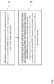
- Fig. 2 shows a flow chart of an exemplary embodiment of a method for controlling the output current of a resonant hybrid flyback converter, comprising a feedback-control unit, a half bridge arrangement comprising a high side switch and a low side switch, and a SELV barrier.
- a feedback signal path indicates the output current on the secondary side of the SELV barrier of the resonant hybrid flyback converter, the feedback signal comprising a current sensing transformer on the secondary side of the SELV barrier and leading to the feedback-control unit arranged on the primary side of the SELV barrier.
Landscapes
- Engineering & Computer Science (AREA)
- Power Engineering (AREA)
- Dc-Dc Converters (AREA)
- Circuit Arrangement For Electric Light Sources In General (AREA)
Priority Applications (2)
| Application Number | Priority Date | Filing Date | Title |
|---|---|---|---|
| EP23202297.0A EP4539323A1 (de) | 2023-10-09 | 2023-10-09 | Resonanter hybrid-flyback-wandler, led-wandler damit und entsprechendes steuerungsverfahren |
| PCT/EP2024/078188 WO2025078322A1 (en) | 2023-10-09 | 2024-10-08 | Resonant hybrid flyback converter, led converter comprising the latter, and corresponding control method |
Applications Claiming Priority (1)
| Application Number | Priority Date | Filing Date | Title |
|---|---|---|---|
| EP23202297.0A EP4539323A1 (de) | 2023-10-09 | 2023-10-09 | Resonanter hybrid-flyback-wandler, led-wandler damit und entsprechendes steuerungsverfahren |
Publications (1)
| Publication Number | Publication Date |
|---|---|
| EP4539323A1 true EP4539323A1 (de) | 2025-04-16 |
Family
ID=88297001
Family Applications (1)
| Application Number | Title | Priority Date | Filing Date |
|---|---|---|---|
| EP23202297.0A Pending EP4539323A1 (de) | 2023-10-09 | 2023-10-09 | Resonanter hybrid-flyback-wandler, led-wandler damit und entsprechendes steuerungsverfahren |
Country Status (2)
| Country | Link |
|---|---|
| EP (1) | EP4539323A1 (de) |
| WO (1) | WO2025078322A1 (de) |
Citations (9)
| Publication number | Priority date | Publication date | Assignee | Title |
|---|---|---|---|---|
| US20160302268A1 (en) * | 2013-12-03 | 2016-10-13 | Tridonic Gmbh & Co Kg | Driver Circuit for Illuminants, Particularly LEDs |
| US20170238379A1 (en) * | 2014-10-17 | 2017-08-17 | Tridonic Gmbh & Co Kg | Operating Circuit for Energizing a Lamp, LED Converter, and Method for Operating an Operating Circuit |
| US20180027621A1 (en) * | 2015-04-17 | 2018-01-25 | Tridonic Gmbh & Co Kg | Converter for light sources |
| EP3269207B1 (de) * | 2015-03-11 | 2020-05-06 | Tridonic GmbH & Co. KG | Isolierte schnittstelle mit stromwandler |
| EP3961892A1 (de) * | 2020-09-01 | 2022-03-02 | Tridonic GmbH & Co. KG | Led-wandler |
| US20220264723A1 (en) * | 2018-07-30 | 2022-08-18 | Lutron Technology Company Llc | Load control device for a light-emitting diode light source |
| US20220393601A1 (en) * | 2019-11-18 | 2022-12-08 | Tridonic Gmbh & Co Kg | Isolated primary side switched converter |
| US20230171863A1 (en) * | 2020-04-24 | 2023-06-01 | Redisem Ltd. | Power Converter and Method of Converting Power |
| EP4220925A1 (de) * | 2022-01-26 | 2023-08-02 | Tridonic GmbH & Co. KG | Schaltwandler |
-
2023
- 2023-10-09 EP EP23202297.0A patent/EP4539323A1/de active Pending
-
2024
- 2024-10-08 WO PCT/EP2024/078188 patent/WO2025078322A1/en active Pending
Patent Citations (9)
| Publication number | Priority date | Publication date | Assignee | Title |
|---|---|---|---|---|
| US20160302268A1 (en) * | 2013-12-03 | 2016-10-13 | Tridonic Gmbh & Co Kg | Driver Circuit for Illuminants, Particularly LEDs |
| US20170238379A1 (en) * | 2014-10-17 | 2017-08-17 | Tridonic Gmbh & Co Kg | Operating Circuit for Energizing a Lamp, LED Converter, and Method for Operating an Operating Circuit |
| EP3269207B1 (de) * | 2015-03-11 | 2020-05-06 | Tridonic GmbH & Co. KG | Isolierte schnittstelle mit stromwandler |
| US20180027621A1 (en) * | 2015-04-17 | 2018-01-25 | Tridonic Gmbh & Co Kg | Converter for light sources |
| US20220264723A1 (en) * | 2018-07-30 | 2022-08-18 | Lutron Technology Company Llc | Load control device for a light-emitting diode light source |
| US20220393601A1 (en) * | 2019-11-18 | 2022-12-08 | Tridonic Gmbh & Co Kg | Isolated primary side switched converter |
| US20230171863A1 (en) * | 2020-04-24 | 2023-06-01 | Redisem Ltd. | Power Converter and Method of Converting Power |
| EP3961892A1 (de) * | 2020-09-01 | 2022-03-02 | Tridonic GmbH & Co. KG | Led-wandler |
| EP4220925A1 (de) * | 2022-01-26 | 2023-08-02 | Tridonic GmbH & Co. KG | Schaltwandler |
Non-Patent Citations (2)
| Title |
|---|
| CHOI W Y ET AL: "Efficient LED back-light power supply for liquid-crystal-display", 20070301, vol. 1, no. 2, 1 March 2007 (2007-03-01), pages 133 - 142, XP006028320 * |
| FRANCESCO SICHIROLLO ET AL: "Use of current controlled mutual inductor to limit recycling current in the AHB-Flyback converter", IECON 2012 - 38TH ANNUAL CONFERENCE ON IEEE INDUSTRIAL ELECTRONICS SOCIETY, IEEE, 25 October 2012 (2012-10-25), pages 4611 - 4616, XP032281786, ISBN: 978-1-4673-2419-9, DOI: 10.1109/IECON.2012.6389504 * |
Also Published As
| Publication number | Publication date |
|---|---|
| WO2025078322A1 (en) | 2025-04-17 |
Similar Documents
| Publication | Publication Date | Title |
|---|---|---|
| JP2010109168A (ja) | Led駆動装置、led駆動方法および照明装置 | |
| US8519642B2 (en) | LED light emitting device | |
| CN101707874B (zh) | 用于可调电流光源的功率控制系统 | |
| US9837913B1 (en) | Control method to avoid capacitive mode switching for resonant converters | |
| US8044609B2 (en) | Circuits and methods for controlling LCD backlights | |
| JP4776596B2 (ja) | 車両用灯具の点灯制御装置 | |
| US8610375B2 (en) | Adaptive bleeder circuit | |
| US10512137B2 (en) | LED drive circuit | |
| US20150091472A1 (en) | Lighting device | |
| US20060231745A1 (en) | Method and circuit arrangement for driving light-emitting diodes | |
| US9398672B2 (en) | Lighting device and illumination apparatus | |
| EP2563095A2 (de) | Beleuchtungsvorrichtung, Scheinwerferbeleuchtungsvorrichtung und Scheinwerfereinheit und Fahrzeug damit | |
| Lohaus et al. | A dimmable LED driver with resistive DAC feedback control for adaptive voltage regulation | |
| US9210748B2 (en) | Systems and methods of driving multiple outputs | |
| US6977830B2 (en) | Power supply apparatus | |
| US7851940B2 (en) | Methods and apparatus for DC-DC converter having independent outputs | |
| US8957592B2 (en) | Electrical power conversion device and lighting device | |
| JP6320455B2 (ja) | Led点灯装置 | |
| JP5289084B2 (ja) | 電源回路及び照明装置 | |
| WO2025078322A1 (en) | Resonant hybrid flyback converter, led converter comprising the latter, and corresponding control method | |
| JP2018019025A (ja) | 電圧変換回路、led駆動回路及び電圧変換回路の制御方法 | |
| US11729883B1 (en) | LED driver with auxiliary output and low standby power | |
| TW200816127A (en) | Lighting apparatus and driving circuit thereof | |
| JP2016170894A (ja) | 点灯装置、照明器具 | |
| JP7484522B2 (ja) | 照明器具、接続ユニットおよび点灯装置 |
Legal Events
| Date | Code | Title | Description |
|---|---|---|---|
| PUAI | Public reference made under article 153(3) epc to a published international application that has entered the european phase |
Free format text: ORIGINAL CODE: 0009012 |
|
| STAA | Information on the status of an ep patent application or granted ep patent |
Free format text: STATUS: THE APPLICATION HAS BEEN PUBLISHED |
|
| AK | Designated contracting states |
Kind code of ref document: A1 Designated state(s): AL AT BE BG CH CY CZ DE DK EE ES FI FR GB GR HR HU IE IS IT LI LT LU LV MC ME MK MT NL NO PL PT RO RS SE SI SK SM TR |
|
| STAA | Information on the status of an ep patent application or granted ep patent |
Free format text: STATUS: REQUEST FOR EXAMINATION WAS MADE |
|
| 17P | Request for examination filed |
Effective date: 20250903 |