EP4539324A1 - Convertisseur indirect hybride résonant pour source lumineuse et luminaire - Google Patents
Convertisseur indirect hybride résonant pour source lumineuse et luminaire Download PDFInfo
- Publication number
- EP4539324A1 EP4539324A1 EP23202323.4A EP23202323A EP4539324A1 EP 4539324 A1 EP4539324 A1 EP 4539324A1 EP 23202323 A EP23202323 A EP 23202323A EP 4539324 A1 EP4539324 A1 EP 4539324A1
- Authority
- EP
- European Patent Office
- Prior art keywords
- voltage
- primary
- converter
- sensing
- current
- Prior art date
- Legal status (The legal status is an assumption and is not a legal conclusion. Google has not performed a legal analysis and makes no representation as to the accuracy of the status listed.)
- Pending
Links
Images


Classifications
-
- H—ELECTRICITY
- H02—GENERATION; CONVERSION OR DISTRIBUTION OF ELECTRIC POWER
- H02M—APPARATUS FOR CONVERSION BETWEEN AC AND AC, BETWEEN AC AND DC, OR BETWEEN DC AND DC, AND FOR USE WITH MAINS OR SIMILAR POWER SUPPLY SYSTEMS; CONVERSION OF DC OR AC INPUT POWER INTO SURGE OUTPUT POWER; CONTROL OR REGULATION THEREOF
- H02M1/00—Details of apparatus for conversion
- H02M1/0048—Circuits or arrangements for reducing losses
- H02M1/0054—Transistor switching losses
- H02M1/0058—Transistor switching losses by employing soft switching techniques, i.e. commutation of transistors when applied voltage is zero or when current flow is zero
-
- H—ELECTRICITY
- H02—GENERATION; CONVERSION OR DISTRIBUTION OF ELECTRIC POWER
- H02M—APPARATUS FOR CONVERSION BETWEEN AC AND AC, BETWEEN AC AND DC, OR BETWEEN DC AND DC, AND FOR USE WITH MAINS OR SIMILAR POWER SUPPLY SYSTEMS; CONVERSION OF DC OR AC INPUT POWER INTO SURGE OUTPUT POWER; CONTROL OR REGULATION THEREOF
- H02M1/00—Details of apparatus for conversion
- H02M1/0003—Details of control, feedback or regulation circuits
- H02M1/0009—Devices or circuits for detecting current in a converter
-
- H—ELECTRICITY
- H02—GENERATION; CONVERSION OR DISTRIBUTION OF ELECTRIC POWER
- H02M—APPARATUS FOR CONVERSION BETWEEN AC AND AC, BETWEEN AC AND DC, OR BETWEEN DC AND DC, AND FOR USE WITH MAINS OR SIMILAR POWER SUPPLY SYSTEMS; CONVERSION OF DC OR AC INPUT POWER INTO SURGE OUTPUT POWER; CONTROL OR REGULATION THEREOF
- H02M3/00—Conversion of DC power input into DC power output
- H02M3/01—Resonant DC/DC converters
-
- H—ELECTRICITY
- H02—GENERATION; CONVERSION OR DISTRIBUTION OF ELECTRIC POWER
- H02M—APPARATUS FOR CONVERSION BETWEEN AC AND AC, BETWEEN AC AND DC, OR BETWEEN DC AND DC, AND FOR USE WITH MAINS OR SIMILAR POWER SUPPLY SYSTEMS; CONVERSION OF DC OR AC INPUT POWER INTO SURGE OUTPUT POWER; CONTROL OR REGULATION THEREOF
- H02M3/00—Conversion of DC power input into DC power output
- H02M3/22—Conversion of DC power input into DC power output with intermediate conversion into AC
- H02M3/24—Conversion of DC power input into DC power output with intermediate conversion into AC by static converters
- H02M3/28—Conversion of DC power input into DC power output with intermediate conversion into AC by static converters using discharge tubes with control electrode or semiconductor devices with control electrode to produce the intermediate AC
- H02M3/325—Conversion of DC power input into DC power output with intermediate conversion into AC by static converters using discharge tubes with control electrode or semiconductor devices with control electrode to produce the intermediate AC using devices of a triode or a transistor type requiring continuous application of a control signal
- H02M3/335—Conversion of DC power input into DC power output with intermediate conversion into AC by static converters using discharge tubes with control electrode or semiconductor devices with control electrode to produce the intermediate AC using devices of a triode or a transistor type requiring continuous application of a control signal using semiconductor devices only
- H02M3/33569—Conversion of DC power input into DC power output with intermediate conversion into AC by static converters using discharge tubes with control electrode or semiconductor devices with control electrode to produce the intermediate AC using devices of a triode or a transistor type requiring continuous application of a control signal using semiconductor devices only having several active switching elements
- H02M3/33571—Half-bridge at primary side of an isolation transformer
-
- H—ELECTRICITY
- H05—ELECTRIC TECHNIQUES NOT OTHERWISE PROVIDED FOR
- H05B—ELECTRIC HEATING; ELECTRIC LIGHT SOURCES NOT OTHERWISE PROVIDED FOR; CIRCUIT ARRANGEMENTS FOR ELECTRIC LIGHT SOURCES, IN GENERAL
- H05B45/00—Circuit arrangements for operating light-emitting diodes [LED]
- H05B45/30—Driver circuits
- H05B45/37—Converter circuits
- H05B45/3725—Switched mode power supply [SMPS]
- H05B45/382—Switched mode power supply [SMPS] with galvanic isolation between input and output
-
- H—ELECTRICITY
- H05—ELECTRIC TECHNIQUES NOT OTHERWISE PROVIDED FOR
- H05B—ELECTRIC HEATING; ELECTRIC LIGHT SOURCES NOT OTHERWISE PROVIDED FOR; CIRCUIT ARRANGEMENTS FOR ELECTRIC LIGHT SOURCES, IN GENERAL
- H05B45/00—Circuit arrangements for operating light-emitting diodes [LED]
- H05B45/30—Driver circuits
- H05B45/37—Converter circuits
- H05B45/3725—Switched mode power supply [SMPS]
- H05B45/385—Switched mode power supply [SMPS] using flyback topology
-
- Y—GENERAL TAGGING OF NEW TECHNOLOGICAL DEVELOPMENTS; GENERAL TAGGING OF CROSS-SECTIONAL TECHNOLOGIES SPANNING OVER SEVERAL SECTIONS OF THE IPC; TECHNICAL SUBJECTS COVERED BY FORMER USPC CROSS-REFERENCE ART COLLECTIONS [XRACs] AND DIGESTS
- Y02—TECHNOLOGIES OR APPLICATIONS FOR MITIGATION OR ADAPTATION AGAINST CLIMATE CHANGE
- Y02B—CLIMATE CHANGE MITIGATION TECHNOLOGIES RELATED TO BUILDINGS, e.g. HOUSING, HOUSE APPLIANCES OR RELATED END-USER APPLICATIONS
- Y02B70/00—Technologies for an efficient end-user side electric power management and consumption
- Y02B70/10—Technologies improving the efficiency by using switched-mode power supplies [SMPS], i.e. efficient power electronics conversion e.g. power factor correction or reduction of losses in power supplies or efficient standby modes
Definitions
- a direct current (DC) input voltage is intermittently applied across a resonant tank circuit.
- the resonant tank circuit may, for example, comprise a transformer's main inductance and leakage inductance (or a separate resonance choke) and a resonance capacitance in series.
- An on-time control of a high-side switch of the switching bridge may be deployed for regulation (i.e., closed-loop control) of a load current of the converter in accordance with corresponding setpoint and measurement values.
- a sensing of the latter typically involves a relatively expensive signal transfer across a safety extra low voltage (SELV) barrier of the converter.
- SELV safety extra low voltage
- a resonant hybrid flyback converter for a light source.
- the converter comprises a transformer, comprising a primary-side inductance and a secondary-side inductance.
- the converter further comprises a high-side switch and a low-side switch, connected in series between an input electric potential and a primary-side ground electric potential of the converter.
- the converter further comprises a resonant tank circuit, connected in series between a common electric potential of the switches and the primary-side ground electric potential.
- the resonant tank circuit comprises the primary-side inductance.
- the converter further comprises a first sensing circuit; a second sensing circuit; and a control circuit.
- the first sensing circuit may comprise a shunt resistance (or sense transformer), connected in series to the primary-side inductance.
- the second sensing circuit may comprise an integration resistance in series with an integration capacitance, connected in parallel to the primary-side inductance.
- a common electric potential of the integration resistance and the integration capacitance may be connected to a second sensing terminal of the control circuit.
- the control circuit may further be configured to sense the second voltage by sampling the second sensing terminal.
- the first sensing circuit may further comprise a first offset resistance, connected between the common electrical potential of the primary-side inductance and the shunt resistance, and a constant current source of the control circuit; and a first filter resistance and a first filter capacitance, connected in series between a common electric potential of the first offset resistance and the constant current source, and the primary-side ground electric potential.
- a common electric potential of the first filter resistance and the first filter capacitance may be connected to a first sensing terminal of the control circuit.
- the control circuit may further be configured to offset the first voltage to a positive value range by sending a constant current of the current source through the first offset resistance; and sense the first voltage by sampling the first sensing terminal.
- a disclosure in connection with a described method may also hold true for a corresponding apparatus or system configured to perform the method and vice versa.
- a corresponding device may include one or a plurality of units, e.g. functional units, to perform the described one or plurality of method steps (e.g. one unit performing the one or plurality of steps, or a plurality of units each performing one or more of the plurality of steps), even if such one or more units are not explicitly described or illustrated in the figures.
- a specific apparatus is described based on one or a plurality of units, e.g.
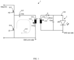
- the converter 1 comprises a resonant hybrid flyback converter 1 for a light source 2 , which may comprise at least one light-emitting diode (LED).
- a light source 2 which may comprise at least one light-emitting diode (LED).
- I LEDest through the light source 2 rather than the actual/measured current 148, I LED through the light source 2 avoids a sensing of the latter and an associated expensive signal transfer across a SELV barrier of the converter 1 .
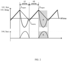
- an amount of energy transferred to the light source 2 is determined by a difference of the magnetizing current 143, I mag and the resonant current 141, I res through the primary-side inductance 101, L p .
- a common electrical potential of the primary-side inductance 101, L p and the shunt resistance 110, R shunt may be connected to a first sensing terminal 131, Sense 1 of the control circuit 130.
- the control circuit 130 may further be configured to sense the first voltage 140 by sampling the first sensing terminal 131, Sense 1 for sensing, via the first sensing circuit 110, the first voltage 140 being indicative of the resonant current 141, I res through the primary-side inductance 101, L p .
- the control circuit 130 may further be configured to sense the second voltage 142 by sampling the second sensing terminal 132, Sense 2 for sensing, via the second sensing circuit 120-121, the second voltage 142 being indicative of the magnetizing current 143, I mag through the primary-side inductance 101, L p .
- the control circuit 130 may further be configured to determine a difference 145, dV of the sensed first voltage 140, V Sense1 and the sensed second voltage 142, V Sense2 .
- dV V Sense 1 ⁇ V Sense 2
- the observed difference the first voltage 140 and the second voltage 142 is not constant and depends on the amount of energy transferred to the light source 2 .
- the first voltage 140 and the second voltage 142 may be matched and the required compensation be sensed.
- the first sensing circuit 110-113 may further comprise a first offset resistance 111 , R offset1 , connected between the common electrical potential of the primary-side inductance 101, L p and the shunt resistance 110, R shunt , and a constant current source 133 of the control circuit 130.
- a common electric potential of the first filter resistance 112, R filter1 and the first filter capacitance 113, C filter1 may be connected to a first sensing terminal 131, Sense 1 of the control circuit 130.
- the second sensing circuit 120-125 may further comprise a second offset resistance 122 , R offset2 and a third offset resistance 123, R offset3 , connected in series between a controllable voltage source 134 , DAC of the control circuit 130 and the primary-side ground electric potential.
- a common electric potential of the second offset resistance 122 , R offset2 and the third offset resistance 123, R offset3 may be connected to the common electric potential of the integration resistance 120, R int and the integration capacitance 121, C int .
- the second sensing circuit 120-125 may further comprise a second filter resistance 124, R filter2 and a second filter capacitance 125, C filter2 , connected in series between the common electric potential of the second offset resistance 122, R offset2 and the third offset resistance 123, R offset3 , and the primary-side ground electric potential.
- the control circuit 130 may further be configured to sense the first voltage 140 by sampling the first sensing terminal 131, Sense 1 .
- a computer program may be stored/distributed on a suitable medium, such as an optical storage medium or a solid-state medium supplied together with or as part of other hardware, but may also be distributed in other forms, such as via the Internet or other wired or wireless telecommunication systems.
- a suitable medium such as an optical storage medium or a solid-state medium supplied together with or as part of other hardware, but may also be distributed in other forms, such as via the Internet or other wired or wireless telecommunication systems.
Landscapes
- Engineering & Computer Science (AREA)
- Power Engineering (AREA)
- Circuit Arrangement For Electric Light Sources In General (AREA)
- Dc-Dc Converters (AREA)
Priority Applications (2)
| Application Number | Priority Date | Filing Date | Title |
|---|---|---|---|
| EP23202323.4A EP4539324A1 (fr) | 2023-10-09 | 2023-10-09 | Convertisseur indirect hybride résonant pour source lumineuse et luminaire |
| PCT/EP2024/078187 WO2025078321A1 (fr) | 2023-10-09 | 2024-10-08 | Convertisseur indirect hybride résonant pour une source de lumière, et luminaire |
Applications Claiming Priority (1)
| Application Number | Priority Date | Filing Date | Title |
|---|---|---|---|
| EP23202323.4A EP4539324A1 (fr) | 2023-10-09 | 2023-10-09 | Convertisseur indirect hybride résonant pour source lumineuse et luminaire |
Publications (1)
| Publication Number | Publication Date |
|---|---|
| EP4539324A1 true EP4539324A1 (fr) | 2025-04-16 |
Family
ID=88297022
Family Applications (1)
| Application Number | Title | Priority Date | Filing Date |
|---|---|---|---|
| EP23202323.4A Pending EP4539324A1 (fr) | 2023-10-09 | 2023-10-09 | Convertisseur indirect hybride résonant pour source lumineuse et luminaire |
Country Status (2)
| Country | Link |
|---|---|
| EP (1) | EP4539324A1 (fr) |
| WO (1) | WO2025078321A1 (fr) |
Citations (5)
| Publication number | Priority date | Publication date | Assignee | Title |
|---|---|---|---|---|
| US8199534B2 (en) * | 2007-02-27 | 2012-06-12 | Nxp B.V. | Load current detection in electrical power converters |
| WO2015103659A2 (fr) * | 2014-01-13 | 2015-07-16 | Tridonic Gmbh & Co Kg | Circuit d'attaque pour moyens d'éclairage, en particulier pour des led |
| WO2018104087A1 (fr) * | 2016-12-07 | 2018-06-14 | Tridonic Gmbh & Co Kg | Agencement de circuits et procédé de fonctionnement d'un moyen d'éclairage |
| US20200021200A1 (en) * | 2018-07-12 | 2020-01-16 | Infineon Technologies Austria Ag | Flyback converter controller, flyback converter and method of operating the flyback converter |
| WO2023144037A1 (fr) * | 2022-01-26 | 2023-08-03 | Tridonic Gmbh & Co Kg | Convertisseur commuté |
-
2023
- 2023-10-09 EP EP23202323.4A patent/EP4539324A1/fr active Pending
-
2024
- 2024-10-08 WO PCT/EP2024/078187 patent/WO2025078321A1/fr active Pending
Patent Citations (5)
| Publication number | Priority date | Publication date | Assignee | Title |
|---|---|---|---|---|
| US8199534B2 (en) * | 2007-02-27 | 2012-06-12 | Nxp B.V. | Load current detection in electrical power converters |
| WO2015103659A2 (fr) * | 2014-01-13 | 2015-07-16 | Tridonic Gmbh & Co Kg | Circuit d'attaque pour moyens d'éclairage, en particulier pour des led |
| WO2018104087A1 (fr) * | 2016-12-07 | 2018-06-14 | Tridonic Gmbh & Co Kg | Agencement de circuits et procédé de fonctionnement d'un moyen d'éclairage |
| US20200021200A1 (en) * | 2018-07-12 | 2020-01-16 | Infineon Technologies Austria Ag | Flyback converter controller, flyback converter and method of operating the flyback converter |
| WO2023144037A1 (fr) * | 2022-01-26 | 2023-08-03 | Tridonic Gmbh & Co Kg | Convertisseur commuté |
Also Published As
| Publication number | Publication date |
|---|---|
| WO2025078321A1 (fr) | 2025-04-17 |
Similar Documents
| Publication | Publication Date | Title |
|---|---|---|
| US10326377B1 (en) | Circuit and method for indirect primary-side load current sensing in an isolated power supply | |
| US8044643B1 (en) | Power supply switching circuit for a halogen lamp | |
| US9923409B2 (en) | Rectification and regulation circuit for a wireless power receiver | |
| US6751107B2 (en) | DC power supply device with constant power output level | |
| US7994736B2 (en) | Cold cathode fluorescent lamp inverter apparatus | |
| US6549436B1 (en) | Integrated magnetic converter circuit and method with improved filtering | |
| US9787195B1 (en) | Primary current sensing method for isolated LED driver | |
| KR20060083162A (ko) | 다출력형 dc-dc 컨버터 | |
| EP0658968A1 (fr) | Régulateur à découpage | |
| JPH07298636A (ja) | 自励式インバータ装置 | |
| US10658932B2 (en) | Power control circuit | |
| TWI516007B (zh) | DC power supply unit | |
| JP2012170218A (ja) | スイッチング電源装置 | |
| EP4539324A1 (fr) | Convertisseur indirect hybride résonant pour source lumineuse et luminaire | |
| US20250158515A1 (en) | Llc voltage converter | |
| EP4535632A1 (fr) | Convertisseur indirect hybride résonant pour source lumineuse et luminaire | |
| WO2025078338A1 (fr) | Convertisseur à transfert indirect hybride résonant pour une source de lumière, et luminaire | |
| JP4720514B2 (ja) | 共振コンバータにおける電流検出方式 | |
| JP3463278B2 (ja) | 電源装置 | |
| US5434769A (en) | Multi-phase adaptable AC-DC converter | |
| EP1313203A2 (fr) | Convrtisseur demi-pont | |
| EP3967110B1 (fr) | Convertisseur à del | |
| WO2020255720A1 (fr) | Convertisseur continu-continu isolé | |
| JP2677738B2 (ja) | スイッチングレギュレータ | |
| EP4525280A1 (fr) | Convertisseur indirect hybride résonant, et agencement de commande et son procédé de fonctionnement |
Legal Events
| Date | Code | Title | Description |
|---|---|---|---|
| PUAI | Public reference made under article 153(3) epc to a published international application that has entered the european phase |
Free format text: ORIGINAL CODE: 0009012 |
|
| STAA | Information on the status of an ep patent application or granted ep patent |
Free format text: STATUS: THE APPLICATION HAS BEEN PUBLISHED |
|
| AK | Designated contracting states |
Kind code of ref document: A1 Designated state(s): AL AT BE BG CH CY CZ DE DK EE ES FI FR GB GR HR HU IE IS IT LI LT LU LV MC ME MK MT NL NO PL PT RO RS SE SI SK SM TR |
|
| STAA | Information on the status of an ep patent application or granted ep patent |
Free format text: STATUS: REQUEST FOR EXAMINATION WAS MADE |
|
| 17P | Request for examination filed |
Effective date: 20250811 |
|
| STAA | Information on the status of an ep patent application or granted ep patent |
Free format text: STATUS: EXAMINATION IS IN PROGRESS |
|
| 17Q | First examination report despatched |
Effective date: 20251209 |