EP4539351A1 - Kommunikationsverfahren und -vorrichtung - Google Patents
Kommunikationsverfahren und -vorrichtung Download PDFInfo
- Publication number
- EP4539351A1 EP4539351A1 EP23834771.0A EP23834771A EP4539351A1 EP 4539351 A1 EP4539351 A1 EP 4539351A1 EP 23834771 A EP23834771 A EP 23834771A EP 4539351 A1 EP4539351 A1 EP 4539351A1
- Authority
- EP
- European Patent Office
- Prior art keywords
- channel state
- indication information
- state indication
- encoder
- model
- Prior art date
- Legal status (The legal status is an assumption and is not a legal conclusion. Google has not performed a legal analysis and makes no representation as to the accuracy of the status listed.)
- Pending
Links
Images






Classifications
-
- H—ELECTRICITY
- H04—ELECTRIC COMMUNICATION TECHNIQUE
- H04B—TRANSMISSION
- H04B7/00—Radio transmission systems, i.e. using radiation field
- H04B7/02—Diversity systems; Multi-antenna system, i.e. transmission or reception using multiple antennas
- H04B7/04—Diversity systems; Multi-antenna system, i.e. transmission or reception using multiple antennas using two or more spaced independent antennas
- H04B7/06—Diversity systems; Multi-antenna system, i.e. transmission or reception using multiple antennas using two or more spaced independent antennas at the transmitting station
- H04B7/0613—Diversity systems; Multi-antenna system, i.e. transmission or reception using multiple antennas using two or more spaced independent antennas at the transmitting station using simultaneous transmission
- H04B7/0615—Diversity systems; Multi-antenna system, i.e. transmission or reception using multiple antennas using two or more spaced independent antennas at the transmitting station using simultaneous transmission of weighted versions of same signal
- H04B7/0619—Diversity systems; Multi-antenna system, i.e. transmission or reception using multiple antennas using two or more spaced independent antennas at the transmitting station using simultaneous transmission of weighted versions of same signal using feedback from receiving side
- H04B7/0621—Feedback content
- H04B7/0626—Channel coefficients, e.g. channel state information [CSI]
-
- H—ELECTRICITY
- H04—ELECTRIC COMMUNICATION TECHNIQUE
- H04B—TRANSMISSION
- H04B7/00—Radio transmission systems, i.e. using radiation field
- H04B7/02—Diversity systems; Multi-antenna system, i.e. transmission or reception using multiple antennas
- H04B7/04—Diversity systems; Multi-antenna system, i.e. transmission or reception using multiple antennas using two or more spaced independent antennas
- H04B7/0413—MIMO systems
-
- H—ELECTRICITY
- H04—ELECTRIC COMMUNICATION TECHNIQUE
- H04B—TRANSMISSION
- H04B7/00—Radio transmission systems, i.e. using radiation field
- H04B7/02—Diversity systems; Multi-antenna system, i.e. transmission or reception using multiple antennas
- H04B7/04—Diversity systems; Multi-antenna system, i.e. transmission or reception using multiple antennas using two or more spaced independent antennas
- H04B7/06—Diversity systems; Multi-antenna system, i.e. transmission or reception using multiple antennas using two or more spaced independent antennas at the transmitting station
-
- H—ELECTRICITY
- H04—ELECTRIC COMMUNICATION TECHNIQUE
- H04B—TRANSMISSION
- H04B7/00—Radio transmission systems, i.e. using radiation field
- H04B7/02—Diversity systems; Multi-antenna system, i.e. transmission or reception using multiple antennas
- H04B7/04—Diversity systems; Multi-antenna system, i.e. transmission or reception using multiple antennas using two or more spaced independent antennas
- H04B7/06—Diversity systems; Multi-antenna system, i.e. transmission or reception using multiple antennas using two or more spaced independent antennas at the transmitting station
- H04B7/0613—Diversity systems; Multi-antenna system, i.e. transmission or reception using multiple antennas using two or more spaced independent antennas at the transmitting station using simultaneous transmission
- H04B7/0615—Diversity systems; Multi-antenna system, i.e. transmission or reception using multiple antennas using two or more spaced independent antennas at the transmitting station using simultaneous transmission of weighted versions of same signal
- H04B7/0619—Diversity systems; Multi-antenna system, i.e. transmission or reception using multiple antennas using two or more spaced independent antennas at the transmitting station using simultaneous transmission of weighted versions of same signal using feedback from receiving side
- H04B7/0621—Feedback content
- H04B7/063—Parameters other than those covered in groups H04B7/0623 - H04B7/0634, e.g. channel matrix rank or transmit mode selection
-
- H—ELECTRICITY
- H04—ELECTRIC COMMUNICATION TECHNIQUE
- H04B—TRANSMISSION
- H04B7/00—Radio transmission systems, i.e. using radiation field
- H04B7/02—Diversity systems; Multi-antenna system, i.e. transmission or reception using multiple antennas
- H04B7/04—Diversity systems; Multi-antenna system, i.e. transmission or reception using multiple antennas using two or more spaced independent antennas
- H04B7/06—Diversity systems; Multi-antenna system, i.e. transmission or reception using multiple antennas using two or more spaced independent antennas at the transmitting station
- H04B7/0613—Diversity systems; Multi-antenna system, i.e. transmission or reception using multiple antennas using two or more spaced independent antennas at the transmitting station using simultaneous transmission
- H04B7/0615—Diversity systems; Multi-antenna system, i.e. transmission or reception using multiple antennas using two or more spaced independent antennas at the transmitting station using simultaneous transmission of weighted versions of same signal
- H04B7/0619—Diversity systems; Multi-antenna system, i.e. transmission or reception using multiple antennas using two or more spaced independent antennas at the transmitting station using simultaneous transmission of weighted versions of same signal using feedback from receiving side
- H04B7/0636—Feedback format
-
- H—ELECTRICITY
- H04—ELECTRIC COMMUNICATION TECHNIQUE
- H04B—TRANSMISSION
- H04B7/00—Radio transmission systems, i.e. using radiation field
- H04B7/02—Diversity systems; Multi-antenna system, i.e. transmission or reception using multiple antennas
- H04B7/04—Diversity systems; Multi-antenna system, i.e. transmission or reception using multiple antennas using two or more spaced independent antennas
- H04B7/06—Diversity systems; Multi-antenna system, i.e. transmission or reception using multiple antennas using two or more spaced independent antennas at the transmitting station
- H04B7/0613—Diversity systems; Multi-antenna system, i.e. transmission or reception using multiple antennas using two or more spaced independent antennas at the transmitting station using simultaneous transmission
- H04B7/0615—Diversity systems; Multi-antenna system, i.e. transmission or reception using multiple antennas using two or more spaced independent antennas at the transmitting station using simultaneous transmission of weighted versions of same signal
- H04B7/0619—Diversity systems; Multi-antenna system, i.e. transmission or reception using multiple antennas using two or more spaced independent antennas at the transmitting station using simultaneous transmission of weighted versions of same signal using feedback from receiving side
- H04B7/0658—Feedback reduction
-
- H—ELECTRICITY
- H04—ELECTRIC COMMUNICATION TECHNIQUE
- H04L—TRANSMISSION OF DIGITAL INFORMATION, e.g. TELEGRAPHIC COMMUNICATION
- H04L1/00—Arrangements for detecting or preventing errors in the information received
- H04L1/0001—Systems modifying transmission characteristics according to link quality, e.g. power backoff
- H04L1/0023—Systems modifying transmission characteristics according to link quality, e.g. power backoff characterised by the signalling
- H04L1/0026—Transmission of channel quality indication
-
- H—ELECTRICITY
- H04—ELECTRIC COMMUNICATION TECHNIQUE
- H04L—TRANSMISSION OF DIGITAL INFORMATION, e.g. TELEGRAPHIC COMMUNICATION
- H04L1/00—Arrangements for detecting or preventing errors in the information received
- H04L1/0001—Systems modifying transmission characteristics according to link quality, e.g. power backoff
- H04L1/0023—Systems modifying transmission characteristics according to link quality, e.g. power backoff characterised by the signalling
- H04L1/0028—Formatting
- H04L1/0029—Reduction of the amount of signalling, e.g. retention of useful signalling or differential signalling
Definitions
- This disclosure relates to the field of communication technologies, and in particular, to a communication method and apparatus.
- this disclosure provides a communication method, including: determining N pieces of first channel state indication information by using a first encoder and channel information of N downlink transport layers input into the first encoder, where N is a positive integer greater than 1; determining second channel state indication information by using a second encoder and the N pieces of first channel state indication information input into the second encoder, where the second channel state indication information corresponds to the N downlink transport layers, and a sequence length corresponding to the second channel state indication information is less than a sum of sequence lengths corresponding to the N pieces of first channel state indication information; and sending the second channel state indication information.
- one or more of a structure of the second encoder, a structure of a second decoder matching the second encoder, or a structure of a second auto-encoder to which the second encoder belongs correspond to the value of N.
- One or more of a structure of the first encoder, a structure of a first decoder matching the first encoder, or a structure of a first auto-encoder to which the first encoder belongs also correspond to the value of N.
- the foregoing information indicating the rank may be further used by a device that receives the information indicating the rank, to determine the structure of the second decoder and/or the structure of the first decoder.
- a range of the sequence length of the second channel state indication information corresponds to one or more of the structure of the first encoder, the structure of the first decoder matching the first encoder, or the structure of the first auto-encoder to which the first encoder belongs, and/or corresponds to the value of N.
- the range of the sequence length of the second channel state indication information may indicate one or more of the structure of the first encoder, the structure of the first decoder matching the first encoder, or the structure of the first auto-encoder to which the first encoder belongs, and/or the value of N.
- the method further includes: sending first information, where the first information indicates one or more of the following: the first encoder, a first decoder matching the first encoder, and a first auto-encoder AE to which the first encoder belongs.
- the information receiving party can quickly determine the first decoder matching the first encoder, improving decoding efficiency.
- the first encoder includes one first AI model, the channel information of the N downlink transport layers is input in serial or parallel into the one first AI model, and the one first AI model correspondingly outputs in serial or parallel the N pieces of first channel state indication information.
- the first encoder includes M first AI models, M is an integer greater than 1 and less than N, channel information of some downlink transport layers in the channel information of the N downlink transport layers is input in serial or parallel into one first AI model in the M first AI models, and the one first AI model correspondingly outputs in serial or parallel first channel state indication information corresponding to the some downlink transport layers.
- one first AI model in the first encoder may be used to process channel information of a plurality of downlink transport layers, so that a quantity of AI models can be reduced, and model storage resources can be reduced.
- the second encoder has a compression function and a quantization function.
- the N pieces of first channel state indication information are input into the second encoder, and the output of the second encoder includes the second channel state indication information.
- the structure of the second encoder may be understood with reference to the following several possible examples.
- N is greater than 2
- the second encoder includes N-1 second AI models.
- An input of a 1 st second AI model in the N-1 second AI models includes a 1 st piece of first channel state indication information and a 2 nd piece of first channel state indication information in the N pieces of first channel state indication information, and an output of the 1 st second AI model includes a 1 st piece of fourth channel state indication information.
- the second encoder includes one second AI model.
- An input of the one second AI model includes the N pieces of first channel state indication information, and an output of the one second AI model includes the third channel state indication information.
- one second AI model is used to process a plurality of pieces of first channel state indication information, so that the model storage resources can be reduced.
- the foregoing design matches the first aspect, so that decompression can be performed twice on channel information obtained by performing compression twice, to restore corresponding channel information.
- a range of the sequence length of the second channel state indication information corresponds to one or more of a structure of a second encoder, a structure of the second decoder matching the second encoder, or a structure of a second auto-encoder to which the second encoder belongs, and/or corresponds to a value of N.
- the range of the sequence length of the second channel state indication information may indicate one or more of the structure of the second encoder, the structure of the second decoder matching the second encoder, or the structure of the second auto-encoder to which the second encoder belongs, and/or the value of N.
- the range of the sequence length of the second channel state indication information may be determined by comparing the sequence length of the second channel state indication information with a corresponding threshold, to determine one or more of the structure of the second encoder, the structure of the second decoder matching the second encoder, or the structure of the second auto-encoder to which the second encoder belongs, and/or the value of N.
- a range of the sequence length of the second channel state indication information corresponds to one or more of a structure of a first encoder, a structure of the first decoder matching the first encoder, or a structure of a first auto-encoder to which the first encoder belongs, and/or corresponds to a value of N.
- the range of the sequence length of the second channel state indication information may indicate one or more of the structure of the first encoder, the structure of the first decoder matching the first encoder, or the structure of the first auto-encoder to which the first encoder belongs, and/or the value of N.
- the range of the sequence length of the second channel state indication information may be determined by comparing the sequence length of the second channel state indication information with a corresponding threshold, to determine one or more of the structure of the first encoder, the structure of the first decoder matching the first encoder, or the structure of the first auto-encoder to which the first encoder belongs, and/or the value of N.
- the method further includes: obtaining information indicating a rank, where a value of N is equal to a value of the rank.
- a structure of the second decoder, a structure of a second encoder matching the second decoder, or a structure of a second auto-encoder to which the second encoder belongs correspond to the value of N.
- One or more of a structure of the first decoder, a structure of a first encoder matching the first decoder, or a structure of a first auto-encoder to which the first encoder belongs also correspond to the value of N.
- N is greater than 2
- the second decoder includes K third AI models
- K is a positive integer greater than 1 and less than N-1
- at least one of the K third AI models is used to restore at least two pieces of first channel state indication information in the N pieces of first channel state indication information.
- N is greater than 2
- the second decoder includes N-1 third AI models.
- An input of an (N-i) th third AI model in the N-1 third AI models includes an (N-i) th piece of fourth channel state indication information.
- An output of the (N-i) th third AI model includes at least one piece of information in the following information: an (N-i) th piece of first channel state indication information in the N pieces of first channel state indication information, an (N-i+1) th piece of first channel state indication information in the N pieces of first channel state indication information, and an (N-i-1) th piece of fourth channel state indication information, where i is a positive integer from 1 to N-1.
- the following describes in detail the structure, an input, and/or an output of the first decoder.
- the first decoder includes one fourth AI model, and the N pieces of first channel state indication information are input in serial or parallel into the one fourth AI model.
- the first decoder includes M fourth AI models, M is an integer greater than 1 and less than N, and some first channel state indication information in the N pieces of first channel state indication information is input in serial or parallel into one fourth AI model in the M fourth AI models.
- the communication module is configured to obtain second channel state indication information.
- the communication module is further configured to obtain information indicating a rank, where a value of N is equal to a value of the rank.
- a structure of the second decoder, a structure of a second encoder matching the second decoder, or a structure of a second auto-encoder to which the second encoder belongs correspond to the value of N.
- One or more of a structure of the first decoder, a structure of a first encoder matching the first decoder, or a structure of a first auto-encoder to which the first encoder belongs also correspond to the value of N.
- the communication module is further configured to obtain second information, where the second information indicates one or more of the following: a second encoder, a decoder matching the second encoder, and a second auto-encoder AE to which the second encoder belongs.
- the communication module is further configured to obtain first information, where the first information indicates one or more of the following: a first encoder, a decoder matching the first encoder, and a first auto-encoder AE to which the first encoder belongs.
- the structure, an input, and/or an output of the second decoder may be understood with reference to the content in the first aspect. Details are not described again in this disclosure.
- this disclosure provides a communication apparatus.
- the communication apparatus includes a processor, configured to implement the method described in the first aspect.
- the processor is coupled to a memory.
- the memory is configured to store instructions and data. When the processor executes the instructions stored in the memory, the method described in the first aspect may be implemented.
- the communication apparatus may further include the memory.
- the communication apparatus may further include a communication interface.
- the communication interface is used by the apparatus to communicate with another device.
- the communication interface may be a transceiver, a circuit, a bus, a module, a pin, or a communication interface of another type.
- the communication apparatus includes:
- the first encoder and the second encoder are implemented in a form of a software function module.
- the first encoder and the second encoder may be implemented in a form of hardware (for example, a chip or a hardware circuit).
- the first encoder and the second encoder may be integrated into the processor, or may be independently deployed in the communication apparatus.
- the communication apparatus may further include the first encoder and the second encoder.
- this disclosure provides a communication apparatus.
- the communication apparatus includes a processor, configured to implement the method described in the second aspect.
- the processor is coupled to a memory.
- the memory is configured to store instructions and data. When the processor executes the instructions stored in the memory, the method described in the second aspect may be implemented.
- the communication apparatus may further include the memory.
- the communication apparatus may further include a communication interface.
- the communication interface is used by the apparatus to communicate with another device.
- the communication interface may be a transceiver, a circuit, a bus, a module, a pin, or a communication interface of another type.
- the communication apparatus includes:
- this disclosure provides a communication system.
- the communication system includes a terminal device and an access network device. Specifically, interaction between the terminal device and the access network device may be understood with reference to the following content.
- the terminal device determines N pieces of first channel state indication information by using a first encoder and channel information of N downlink transport layers input into the first encoder, where N is a positive integer greater than 1.
- the terminal device determines second channel state indication information by using a second encoder and the N pieces of first channel state indication information input into the second encoder, where the second channel state indication information corresponds to the N downlink transport layers, and a sequence length corresponding to the second channel state indication information is less than a sum of sequence lengths corresponding to the N pieces of first channel state indication information.
- the terminal device sends the second channel state indication information to the access network device.
- the access network device receives the second channel state indication information from the terminal device.
- a solution implemented on a terminal device side may be understood with reference to the designs described in the first aspect.
- a solution implemented on an access network device side may be understood with reference to the designs described in the second aspect. Details are not described again in this disclosure.
- this disclosure further provides a computer program product, including instructions.
- the instructions When the instructions are run on a computer, the computer is enabled to perform the method provided in the first aspect or the second aspect.
- this disclosure further provides a chip.
- the chip is configured to read a computer program stored in a memory, to perform the method provided in the first aspect or the second aspect.
- the chip includes a circuit configured to perform the method provided in the first aspect or the second aspect.
- the communication system may be a 3rd generation (3rd generation, 3G) communication system (for example, a universal mobile telecommunications system (universal mobile telecommunications system, UMTS)), a 4th generation (4th generation, 4G) communication system (for example, a long term evolution (long term evolution, LTE) system), a 5th generation (5th generation, 5G) communication system, a worldwide interoperability for microwave access (worldwide interoperability for microwave access, WiMAX) or wireless local area network (wireless local area network, WLAN) system, a converged system of a plurality of systems, or a future communication system, for example, a 6G communication system.
- the 5G communication system may also be referred to as a new radio (new radio, NR) system.
- a network element in the communication system may send a signal to another network element or receive a signal from another network element.
- the signal may include information, signaling, data, or the like.
- the network element may alternatively be replaced with an entity, a network entity, a device, a communication device, a communication module, a node, a communication node, or the like.
- the network element is used as an example for description.
- the communication system may include at least one terminal device and at least one access network device.
- the access network device may send a downlink signal to the terminal device, and/or the terminal device may send an uplink signal to the access network device.
- the communication system includes a plurality of terminal devices, the plurality of terminal devices may also send signals to each other. In other words, both a signal sending network element and a signal receiving network element may be terminal devices.
- FIG. 1 is a simplified diagram of the wireless communication system according to an embodiment of this application.
- the wireless communication system includes a radio access network 100.
- the radio access network 100 may be a next generation (for example, 6G or a higher version) radio access network, or a conventional (for example, 5G, 4G, 3G, or 2G) radio access network.
- One or more communication devices 120a to 120j, which are collectively referred to as 120
- FIG. 1 is only a diagram.
- the wireless communication system may further include another device, for example, may further include a core network device, a wireless relay device, and/or a wireless backhaul device, which are not shown in FIG. 1 .
- the wireless communication system may include a plurality of network devices (also referred to as access network devices), or may include a plurality of communication devices.
- One network device may simultaneously serve one or more communication devices.
- One communication device may also simultaneously access one or more network devices. Quantities of communication devices and network devices included in the wireless communication system are not limited in this embodiment of this application.
- the network device may be an entity that is configured to send or receive a signal on a network side.
- the network device may be an access device via which the communication device accesses the wireless communication system in a wireless manner.
- the network device may be a base station.
- the base station may cover the following names in a broad sense, or may be replaced with the following names, for example, a NodeB (NodeB), an evolved NodeB (evolved NodeB, eNB), a next generation NodeB (next generation NodeB, gNB), an access network device in an open radio access network (open radio access network, O-RAN), a relay station, an access point, a transmission point (transmitting and receiving point, TRP), a transmitting point (transmitting point, TP), a master station MeNB, a secondary station SeNB, a multi-standard radio (MSR) node, a home base station, a network controller, an access node, a radio node, an access point (AP), a transmission
- the network device may be a mobile switching center, a device that takes on a base station function in device-to-device (Device-to-Device, D2D), vehicle-to-everything (vehicle-to-everything, V2X), and machine-to-machine (machine-to-machine, M2M) communication, a network side device in a 6G network, a device that takes on a base station function in a future communication system, or the like.
- the network device may support networks using a same access technology or different access technologies. A specific technology and a specific device form that are used by the network device are not limited in embodiments of this application.
- the network device may be fixed or mobile.
- the base stations 110a and 110b are stationary and are responsible for wireless transmission and reception in one or more cells from the communication device 120.
- a helicopter or uncrewed aerial vehicle 120i shown in FIG. 1 may be configured to serve as a mobile base station, and one or more cells may move based on a location of the mobile base station 120i.
- the helicopter or uncrewed aerial vehicle (120i) may be configured to serve as a communication device communicating with the base station 110b.
- Some examples of the communication device 120 are 3GPP user equipment (UE), a fixed device, a mobile device, a handheld device, a wearable device, a cellular phone, a smartphone, a session initiation protocol (SIP) phone, a notebook computer, a personal computer, a smart book, a vehicle, a satellite, a global positioning system (GPS) device, a target tracking device, an uncrewed aerial vehicle, a helicopter, an aircraft, a ship, a remote control device, a smart home device, an industrial device, a personal communication service (personal communication service, PCS) phone, a wireless local loop (wireless local loop, WLL) station, a personal digital assistant (personal digital assistant, PDA), a wireless network camera, a tablet computer, a palmtop computer, a mobile internet device (mobile internet device, MID), a wearable device such as a smartwatch, a virtual reality (virtual reality, VR) device, an augmented reality (augmented reality, AR) device, a wireless terminal in industrial control (
- the communication device may be configured to serve as a base station.
- the UE may serve as a scheduling entity that provides sidelink signals between UEs in V2X, D2D, P2P, or the like.
- the cellular phone 120a and a car 120b communicate with each other by using sidelink signals.
- the cellular phone 120a communicates with a smart home device 120e without relaying a communication signal via the base station 110b.
- the primary device may be a network device or a communication device.
- the secondary device may be another network device or a communication device.
- the primary device is a communication device
- the secondary device may be another communication device.
- the primary device is a network device, for example, an access network device
- the secondary device is a communication device, for example, a terminal device.
- a communication direction corresponding to downlink is sending from the primary device to the secondary device
- a communication direction corresponding to uplink is sending from the secondary device to the primary device.
- the terminal device may further have an application layer and a non-access stratum.
- the application layer may be used to provide a service for an application installed on the terminal device.
- downlink data received by the terminal device may be sequentially transmitted from the physical layer to the application layer, and then is provided by the application layer for the application.
- the application layer may obtain data generated by the application, and sequentially transmit the data to the physical layer, and the data is sent to another communication apparatus.
- the non-access stratum may be used to forward user data, for example, forward uplink data received from the application layer to the SDAP layer or forward downlink data received from the SDAP layer to the application layer.
- the DU and the RU may be distinguished at a physical layer (physical layer, PHY).
- PHY physical layer
- the DU may implement a higher-layer function of the PHY layer
- the RU may implement a lower-layer function of the PHY layer.
- a function of the PHY layer may include cyclic redundancy check (cyclic redundancy check, CRC) code addition, channel encoding, rate matching, scrambling, modulation, layer mapping, precoding, resource mapping, physical antenna mapping, and/or radio frequency sending functions.
- CRC cyclic redundancy check
- any one of the DU, the CU, the CU-CP, the CU-UP, and the RU may be a software module, a hardware structure, or a combination of a software module and a hardware structure.
- the DU, the CU, the CU-CP, and the CU-UP are software modules
- the RU is a hardware structure. The modules and methods performed by the modules also fall within the protection scope of this disclosure.
- the method provided in this disclosure may be used for communication between the access network device and the terminal device, and may also be used for communication between other communication devices, for example, communication between a macro base station and a micro base station in a wireless backhaul link, or communication between two terminal devices in a sidelink (sidelink, SL). This is not limited.
- the access network device In a frequency division duplex (frequency division duplex, FDD) communication scenario, because uplink and downlink channels do not have reciprocity or reciprocity between uplink and downlink channels cannot be ensured, the access network device usually sends a downlink reference signal to the terminal device.
- the terminal device performs channel measurement and interference measurement based on the received downlink reference signal, to estimate downlink channel information.
- the downlink channel information includes CSI. Then, the CSI is fed back to the access network device.
- the terminal device may generate a CSI report based on the estimated CSI in a manner predefined or configured by the access network device, and feed back the CSI report to the access network device.
- the downlink reference signal includes a channel state information-reference signal (channel state information-reference signal, CSI-RS) or a synchronization signal block (synchronization signal/physical broadcast channel block, SSB).
- the CSI report includes a feedback quantity, for example, a rank indicator (rank indicator, RI), a channel quality indicator (channel quality indicator, CQI), and a precoding matrix indicator (precoding matrix indicator, PMI).
- the RI indicates a quantity of downlink transport layers recommended by the terminal device.
- the CQI indicates a modulation and coding scheme that is determined by the terminal device and that can be supported by a current channel condition.
- the PMI indicates precoding recommended by the terminal device.
- a quantity of precoding layers indicated by the PMI corresponds to the RI. For example, if the RI is 1, the PMI indicates single-layer precoding; or if the RI is N, the PMI indicates N-layer precoding, where N is a positive integer greater than 1. It may be understood that N precoding layers respectively correspond to N downlink transport layers indicated by the RI. It can be learned that a larger quantity of downlink transport layers indicated by the RI indicates higher PMI feedback overheads.
- a PMI indicating single-layer precoding is referred to as a single-layer PMI for short
- a PMI indicating N-layer precoding is referred to as an N-layer PMI for short.
- the following describes common information and independent information at each layer in the single-layer to four-layer PMIs by using i 1 and i 2 .
- i 1 and i 2 1 st rows correspond to the single-layer PMI, 2 nd rows correspond to a two-layer PMI, 3 rd rows correspond to a three-layer PMI, and 4 th rows correspond to the four-layer PMI.
- the four-layer PMI is used as an example. It may be understood that i 1,1 , i 1,2 , and i 1,5 are common information between four precoding layers. i 1,1 represents DFT spatial basis selection. i 1,2 represents spatial oversampling selection. i 1,5 represents DFT frequency domain basis subset selection.
- the CSI of the plurality of downlink transport layers is usually considered as mutually independent information.
- the terminal device independently compresses and feeds back CSI of the layer by using an AI model.
- the access network device receives the compressed CSI corresponding to each of the plurality of downlink transport layers. Then, the access network device restores the compressed CSI corresponding to the plurality of downlink transport layers.
- Such a design of independently compressing and feeding back CSI of a plurality of layers causes repeated transmission of some common information (for example, DFT spatial basis selection, spatial oversampling selection, and DFT frequency domain basis subset selection) in the CSI of the plurality of layers, resulting in a waste of resources.
- some common information for example, DFT spatial basis selection, spatial oversampling selection, and DFT frequency domain basis subset selection
- An AI model is a specific implementation of an AI function.
- the AI model represents a mapping relationship between an input and an output of a model.
- a type of the AI model may be a neural network, a linear regression model, a decision tree model, a support vector machine (support vector machine, SVM), a Bayesian network, a Q-learning model, or another machine learning (machine learning, ML) model.
- This disclosure relates to an encoder configured to compress CSI and a decoder configured to restore compressed CSI.
- the encoder and the decoder need to be used together. It may be understood that the encoder and the decoder are matching AI models.
- one encoder may include one or more AI models, and a decoder matching the encoder also includes one or more AI models, where the AI models included in the encoder are the same in quantity as and in one-to-one correspondence with the AI models included in the decoder matching the encoder.
- a set of encoder (encoder) and decoder (decoder) that are used together may be specifically two parts of a same auto-encoder (auto-encoder, AE).
- the auto-encoder is an unsupervised learning neural network, and is characterized by using input data as label data. Therefore, the auto-encoder may also be understood as a self-supervised learning neural network.
- the auto-encoder may be configured to compress and restore data.
- the encoder in the auto-encoder may perform compression (encoding) processing on data A to obtain data B
- the decoder in the auto-encoder may perform decompression (decoding) processing on the data B to restore the data A.
- the decoder performs an inverse operation of the encoder.
- a neural network is a specific implementation form of an AI or machine learning technology. According to a universal approximation theorem, the neural network can theoretically approximate any continuous function, so that the neural network has a capability of learning any mapping.
- An offset for performing weighted summation on the input values based on the weights is, for example, b.
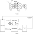
- the neural network generally includes a plurality of layers, and each layer may include one or more neurons.
- a depth and/or a width of the neural network are/is increased, so that an expression capability of the neural network can be improved, and a more powerful information extraction and abstraction modeling capability can be provided for a complex system.
- the depth of the neural network may be a quantity of layers included in the neural network, and a quantity of neurons included in each layer may be referred to as a width of the layer.
- the neural network includes an input layer and an output layer.
- the input layer of the neural network performs neuron processing on received input information, and transfers a processing result to the output layer.
- the output layer obtains an output result of the neural network.
- the type of the AI model is a neural network.
- the AI model in this disclosure may be a deep neural network (deep neural network, DNN).
- the DNN may include a feedforward neural network (feedforward neural network, FNN), a convolutional neural network (convolutional neural network, CNN), and a recurrent neural network (recurrent neural network, RNN).
- a training dataset is used for training an AI model.
- the training dataset may include an input of the AI model, or include an input and a target output of the AI model.
- the training dataset includes one or more pieces of training data.
- the training data may be a training sample input into the AI model, or may be the target output of the AI model.
- the target output may also be referred to as a label or a label sample.
- the training dataset is one of important parts of machine learning. In essence, model training is to learn some features from the training data, so that an output of the AI model is as close as possible to the target output, for example, a difference between the output of the AI model and the target output is minimized.
- the composition and selection of the training dataset can determine performance of a trained AI model to some extent.
- Inference data may be used as an input of a trained AI model for AI model inference.
- the inference data is input into an AI model, to obtain a corresponding output, that is, an inference result.
- An AI model design mainly includes a data collection phase (for example, collection of training data and/or inference data), a model training phase, and a model inference phase. Further, an inference result application phase may be included.
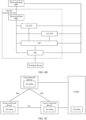
- FIG. 2C shows an AI application framework.
- a data source data source
- the training data training data
- the AI model represents a mapping relationship between an input and an output of a model. Obtaining the AI model through learning by using a model training node is equivalent to obtaining the mapping relationship between the input and the output of the model through learning by using the training data.
- the AI model obtained through training in the model training phase is used to perform inference based on the inference data provided by the data source, to obtain an inference result.
- This phase may also be understood as follows:
- the inference data is input into the AI model, to obtain the output through the AI model.
- the output is the inference result.
- the inference result may indicate a configuration parameter used (acted) by an execution object, and/or an operation performed by the execution object.
- the inference result is released in the inference result application phase.
- the inference result may be planned by an execution (actor) entity in a unified manner.
- the execution entity may send the inference result to one or more execution objects (for example, a core network device, an access network device, or a terminal device) for execution.
- the execution entity may further feed back performance of the model to the data source, to facilitate subsequent model update training.
- one parameter or a plurality of parameters may be obtained through inference by using one model.
- Learning processes of different models may be deployed on different devices or nodes, or may be deployed on a same device or node.
- Inference processes of different models may be deployed on different devices or nodes, or may be deployed on a same device or node.
- the terminal device completes the model training phase, and after training an encoder and decoder that can be trained together, the terminal device may send a model parameter of the decoder to the access network device.
- the access network device completes the model training phase, and after training an encoder and decoder that can be trained together, the access network device may indicate a model parameter of the encoder to the terminal device.
- an independent AI network element completes the model training phase, and after training an encoder and decoder that can be trained together, the AI network element may send a model parameter of the encoder to the terminal device, and send a model parameter of the decoder to the access network device, so that a model inference phase corresponding to the encoder is performed on the terminal device, and a model inference phase corresponding to the decoder is performed on the access network device.
- this disclosure further provides several network architectures shown in FIG. 4A to FIG. 4D .
- An example in which model training and/or inference are/is performed in an access network device is used, and division is performed in the access network device to obtain function modules for model training and/or inference.
- the CU and the DU may exchange the inference result.
- the DU and the RU may exchange the inference result.
- the near-real-time RIC submits the inference result to the DU
- the DU submits the inference result to the RU.
- a non-real-time RIC may be included outside the access network device.
- the non-real-time RIC may be located in OAM or a core network device.
- the non-real-time RIC is configured to perform model learning and inference.
- the non-real-time RIC may obtain information on a network side and/or a terminal side from at least one of a CU, a DU, and an RU, where the information may include training data or inference data.
- the non-real-time RIC is configured to perform model training, and may further perform inference by using a trained model.
- the non-real-time RIC may submit an inference result to at least one of the CU, the DU, and the RU.
- the CU and the DU may exchange the inference result.
- the DU and the RU may exchange the inference result.
- the non-real-time RIC submits the inference result to the DU
- the DU submits the inference result to the RU.
- the non-real-time RIC is configured to perform model training and perform inference by using a trained model, and the near-real-time RIC does not participate in model training or inference.
- the near-real-time RIC is configured to perform model training and send a model parameter of a trained AI model to the non-real-time RIC, and the non-real-time RIC performs inference by using the trained model.
- FIG. 4B is an example diagram of a network architecture to which a method provided in this disclosure can be applied.
- a CU is separated into a CU-CP and a CU-UP.
- FIG. 4C is an example diagram of a network architecture to which a method provided in this disclosure can be applied.
- the access network device includes one or more AI entities, and a function of the AI entity is similar to that of the foregoing near-real-time RIC.
- OAM includes one or more AI entities, and a function of the AI entity is similar to that of the foregoing non-real-time RIC.
- a core network device includes one or more AI entities, and a function of the AI entity is similar to that of the foregoing non-real-time RIC.
- models obtained through training by the AI entities of the OAM and the core network device are different, and/or models for inference are different.
- that the models are different includes at least one of the following: structure parameters of the models (for example, quantities of layers and/or weights of the models) are different, input parameters of the models are different, or output parameters of the models are different.
- This disclosure relates to CSI compression in two phases.
- a terminal device separately compresses CSI of a plurality of layers by using a first encoder.
- the terminal device compresses a result in the first phase by using a second encoder.
- decompression of two phases is also needed on an access network device side. For example, an access network device first performs decompression by using a second decoder matching the second encoder, and then decompresses an output of the second decoder by using a first decoder matching the first encoder.
- the first encoder and the first decoder are used and trained together. It may be understood that a quantity of AI models included in the first encoder is the same as a quantity of AI models included in the first decoder, and each AI model in the first encoder has a corresponding matching AI model in the first decoder.
- a training dataset used to train the first encoder and the first decoder includes a training sample and a sample label, where the training sample is channel information of a downlink transport layer determined by the terminal device, and the sample label is real channel information of the downlink transport layer.
- training data includes only the training sample, or the training sample is the sample label, that is, the channel information of the downlink transport layer.
- a specific training process is as follows: A model training node processes channel information of a downlink transport layer, that is, a training sample, by using the first encoder, to obtain first channel state indication information corresponding to the downlink transport layer, and processes the first channel state indication information by using the first decoder, to obtain restored channel information of the downlink transport layer.
- a sequence length of the first channel state indication information may be a first target length. Optionally, there may be one or more first target lengths.
- a difference between the restored channel information of the downlink transport layer and a corresponding sample label is calculated, that is, a value of a loss function, and parameters of the first encoder and the first decoder are updated based on the value of the loss function, to minimize the difference between the restored channel information of the downlink transport layer and the corresponding sample label, that is, to minimize the loss function.
- the loss function may be a minimum mean square error (mean square error, MSE) or a cosine similarity.
- the target requirement includes one or more of a target length and/or restoration accuracy.
- the model training node may be the terminal device, the access network device, or another network element having an AI function in a communication system. Further, if the model training node is the terminal device, a model parameter of the first decoder may be sent to the access network device; if the model training node is the access network device, a model parameter of the first encoder may be sent to the terminal device; or if the model training node is another network element other than the terminal device and the access network device, a model parameter of the first encoder may be sent to the terminal device, and a model parameter of the first decoder may be sent to the access network device.
- the second encoder and the second decoder are used and trained together. It may be understood that a quantity of AI models included in the second encoder is the same as a quantity of AI models included in the second decoder, and each AI model in the second encoder has a corresponding matching AI model in the second decoder. Because the second encoder compresses a result of the first encoder, the second encoder and the second decoder cannot be used independently of the first encoder and the first decoder, that is, the second encoder and the second decoder need to be trained together with the first encoder and the first decoder. In a possible design, the second encoder and the second decoder belong to a same auto-encoder.
- the second encoder and the second decoder may be trained together with a trained first encoder and first decoder, or may be trained together with an untrained first encoder and first decoder.
- the first encoder and the first decoder may be fixed, and only the second encoder and the second decoder are trained; or the second encoder and the second decoder may be jointly trained, and the first encoder and the second decoder may be jointly trained.
- the second encoder and the second decoder each include one AI model.
- a specific training process is as follows: A model training node processes channel information of N downlink transport layers by using the first encoder, to obtain N pieces of first channel state indication information, processes the N pieces of first channel state indication information by using the second encoder, to obtain second channel state indication information, processes the second channel state indication information by using the second decoder, to obtain restored N pieces of first channel state indication information, and processes the restored N pieces of first channel state indication information by using the first decoder, to obtain restored channel information of the N downlink transport layers.
- a sequence length of the second channel state indication information may be a second target length.
- the foregoing operations are repeated for a plurality of second target lengths, to obtain a second encoder and second decoder that meet a target requirement and that are obtained through training, that is, obtained after training is completed.
- the target requirement includes one or more of a target length and/or restoration accuracy.
- the model training node may be the terminal device, the access network device, or another network element having an AI function in a communication system.
- a model parameter of the second decoder may be sent to the access network device; if the model training node is the access network device, a model parameter of the second encoder may be sent to the terminal device; or if the model training node is another network element other than the terminal device and the access network device, a model parameter of the second encoder may be sent to the terminal device, and a model parameter of the second decoder may be sent to the access network device.
- S501 A terminal device determines channel information of N downlink transport layers.
- the first encoder may be obtained through training in the foregoing training process.
- a structure of the first encoder may be understood with reference to any one of the following Manner 11, Manner 12, or Manner 13.
- the first encoder includes one first AI model.
- the terminal device may process the channel information of the N downlink transport layers by using the one first AI model, to obtain the N pieces of first channel state indication information.
- the channel information of the N downlink transport layers is input into the one first AI model, and correspondingly, an output of the first encoder includes the N pieces of first channel state indication information.
- the terminal device may input the channel information of the N downlink transport layers in parallel or serial into the one first AI model. This is not limited in this disclosure.
- one first AI model may be trained to use, as input data, the downlink channel information estimated by measuring the downlink reference signal and output the N pieces of first channel state indication information.
- the terminal device may directly process the downlink channel information by using the one first AI model, to obtain the N pieces of first channel state indication information.
- the first encoder may include N first AI models, and an i th first AI model in the first encoder is used to process channel information of an i th downlink transport layer in the N downlink transport layers, to obtain an i th piece of first channel state indication information in the N pieces of first channel state indication information.
- the channel information of the N downlink transport layers is respectively input into the N first AI models
- an input of the i th first AI model in the N first AI models includes the channel information of the i th downlink transport layer in the N downlink transport layers
- an output of the i th first AI model includes the i th piece of first channel state indication information corresponding to the i th downlink transport layer.
- the N first AI models in the first encoder may be the same.
- model types for example, used neural networks
- model parameters are different.
- both model types and model parameters of the N first AI models are different. This is not limited in this disclosure.
- the structure of the first encoder may be preconfigured in one of Manner 11, Manner 12, or Manner 13.
- the structure is preconfigured through definition by using a protocol or in another definition manner.
- the structure may be preconfigured through negotiation between the terminal device and the access network device.
- the terminal device may determine the structure of the first encoder in one of Manner 11, Manner 12, or Manner 13.
- the terminal device may send first indication information to the access network device, where the first indication information indicates the structure of the first encoder.
- the first indication information specifically indicates that the structure of the first encoder is as in Manner 11, Manner 12, or Manner 13.
- a mapping relationship between different values of N and the structure of the first encoder may be further preconfigured, or it may be described that the structure of the first encoder corresponds to the value of N.
- a model type and a model parameter of each first AI model in the first encoder may be further preconfigured.
- the terminal device may report, to the access network device, an identifier, a model type, a model parameter, or the like of the first AI model in the first encoder used by the terminal device.
- the first indication information indicates Manner 11
- an identifier, a model type, a model parameter, or the like of the first AI model in the first encoder in Manner 11 may be specifically indicated.
- the terminal device determines second channel state indication information by using a second encoder and the N pieces of first channel state indication information input into the second encoder, where the second channel state indication information corresponds to the N downlink transport layers.
- the terminal device may process the N pieces of first channel state indication information by using the second encoder, to obtain the second channel state indication information.
- An input of the second encoder includes the N pieces of first channel state indication information
- an output of the second encoder includes the second channel state indication information. It may be understood that the second channel state indication information obtained in S503 is a compression of the N pieces of first channel state indication information obtained in S502.
- the second channel state indication information may also be understood as a sequence, and a sequence length corresponding to the second channel state indication information is less than a sum of sequence lengths corresponding to the N pieces of first channel state indication information.
- the second encoder in Solution 1 has a compression function and a quantization function, and processing on the N pieces of first channel state indication information includes compression and quantization.
- the sequence corresponding to the second channel state indication information may be specifically a bit sequence.
- the second encoder may be obtained through training in the foregoing training process.
- a structure of the second encoder refer to any one of the following Manner 21, Manner 22, or Manner 23.
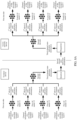
- FIG. 6A is a schematic flowchart of encoding.
- N 4
- the first encoder in S502 includes four first AI models, that is, a first AI model 11, a first AI model 12, a first AI model 13, and a first AI model 14, and the second encoder includes one second AI model.
- different second encoders may be set for different quantities of downlink transport layers.
- the one second AI model included in the second encoder is associated with the value of N, and different values of N are associated with different second AI models.
- N the second encoder is denoted as an encoder 22 or an encoder in an AE model 22; or when N is 3, the second encoder is denoted as an encoder 32 or an encoder in an AE model 32.
- Such a design can enhance the AI model application flexibility.
- it is optionally set that a same second encoder or an encoder in a same AE model is correspondingly used for different quantities of downlink transport layers. Such a design can reduce the AI model storage overheads.
- an input of an i th encoder includes an (i-1) th piece of fourth channel state indication information output by an (i-1) th encoder and an (i+1) th piece of first channel state indication information in the N pieces of first channel state indication information
- an output of the i th encoder includes an i th piece of fourth channel state indication information, where 2 ⁇ i ⁇ N-1, and i is a positive integer, that is, i is a positive integer from 2 to N-1.
- an (N-1) th piece of fourth channel state indication information output by an (N-1) th second AI model is the second channel state indication information.
- K may be 2
- the second encoder may include two second AI models, denoted as a second AI model 21 and a second AI model 22.
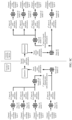
- FIG. 6C is a schematic flowchart of encoding.
- N is 4, the first encoder in S502 includes four first AI models, that is, a first AI model 11, a first AI model 12, a first AI model 13, and a first AI model 14, and the second encoder in S503 includes two second AI models, that is, the second AI model 21 and the second AI model 22.
- An input of the first AI model 11 includes channel information of a downlink transport layer 1, and an output of the first AI model 11 includes a 1 st piece of first channel state indication information.
- K may be 2 or 3, that is, the second encoder may include two second AI models or three second AI models.
- the case in which the second encoder includes two second AI models may be understood with reference to the example in which N is 4.
- the case in which the second encoder includes three second AI models may be understood according to the following content.
- an input of the second AI model 21 includes a 1 st to 3 rd pieces of first channel state indication information in five pieces of first channel state indication information, and an output of the second AI model 21 includes a 1 st piece of fourth channel state indication information.
- An input of the second AI model 22 includes a 4 th piece of first channel state indication information in the five pieces of first channel state indication information and the 1 st piece of fourth channel state indication information, and an output of the second AI model 22 includes a 2 nd piece of fourth channel state indication information.
- An input of the second AI model 23 includes a 5 th piece of first channel state indication information in the five pieces of first channel state indication information and the 2 nd piece of fourth channel state indication information, and an output of the second AI model 23 includes a 3 rd piece of fourth channel state indication information.
- the 3 rd piece of fourth channel state indication information output by the second AI model 23 is the second channel state indication information.
- an input of the second AI model 21 includes a 1 st piece of first channel state indication information and a 2 nd piece of first channel state indication information in five pieces of first channel state indication information
- an output of the second AI model 21 includes a 1 st piece of fourth channel state indication information
- An input of the second AI model 22 includes a 3 rd piece of first channel state indication information and a 4 th piece of first channel state indication information in the five pieces of first channel state indication information
- an output of the second AI model 22 includes a 2 nd piece of fourth channel state indication information.
- An input of the second AI model 23 includes a 5 th piece of first channel state indication information in the five pieces of first channel state indication information, the 1 st piece of fourth channel state indication information, and the 2 nd piece of fourth channel state indication information, and an output of the second AI model 23 includes a 3 rd piece of fourth channel state indication information.
- the 3 rd piece of fourth channel state indication information output by the second AI model 23 is the second channel state indication information.
- An input of the second AI model 21 includes a 1 st piece of first channel state indication information and a 2 nd piece of first channel state indication information in five pieces of first channel state indication information, and an output of the second AI model 21 includes a 1 st piece of fourth channel state indication information.
- An input of the second AI model 22 includes a 3 rd piece of first channel state indication information to a 5 th piece of first channel state indication information in the five pieces of first channel state indication information, and an output of the second AI model 22 includes a 2 nd piece of fourth channel state indication information.
- the structure of the second encoder may be preconfigured in one of Manner 21, Manner 22, or Manner 23.
- the structure is preconfigured through definition by using a protocol or in another definition manner.
- the structure may be preconfigured through negotiation between the terminal device and the access network device.
- the terminal device may determine the structure of the second encoder in one of Manner 21, Manner 22, or Manner 23.
- the terminal device may send second indication information to the access network device, where the second indication information indicates the structure of the second encoder.
- the second indication information specifically indicates that the structure of the second encoder is as in Manner 21, Manner 22, or Manner 23.
- a mapping relationship between different values of N and the structure of the second encoder may be further preconfigured, or it may be described that the structure of the second encoder corresponds to the value of N.
- the terminal device may report, to the access network device, one or more of an identifier, a model type, a model parameter, or the like of the second AI model in the second encoder used by the terminal device.
- the second indication information indicates Manner 21
- one or more of an identifier, a model type, a model parameter, or the like of the second AI model in the second encoder in Manner 21 may be specifically indicated.
- S504 The terminal device sends the second channel state indication information to the access network device.
- the terminal device may be predefined that the terminal device feeds back, to the access network device, CSI obtained by performing compression twice, or the terminal device and the access network device may negotiate in advance to feed back CSI obtained by performing compression twice.
- the access network device may determine that decompression needs to be performed twice on the second channel state indication information, and further perform S505 and S506.
- the terminal device when sending the second channel state indication information, may further send information indicating a rank, for example, an RI, where the value of the quantity N of downlink transport layers is equal to a value of the rank.
- the RI indicates the value of N.
- the access network device may also learn, based on the RI, that the second channel state indication information is obtained by the terminal device by performing compression twice. In such a design, existing information is used to additionally define or indicate other content, so that information utilization can be improved.
- the structure of the second encoder corresponds to the value of N.
- a structure of a second decoder matching the second encoder also corresponds to the value of N.
- the access network device may determine one or more of the structure of the second encoder, the structure of the second decoder, or the structure of the second auto-encoder based on the value of N.
- the structure of the first encoder may also correspond to the value of N.
- a structure of a first decoder matching the first encoder also corresponds to the value of N.
- an independent piece of information may be defined, for example, denoted as second information.
- the second information indicates one or more of the following: the second encoder, the auto-encoder AE to which the second encoder belongs, and the second decoder matching the second encoder.
- the terminal device may further send the second information.
- the access network device may determine, based on the second information, the second decoder matching the second encoder.
- the second information may include one or more of a model identifier, a model type, and a model parameter of the second encoder.
- first information may also be separately defined, and the first information indicates one or more of the following: the first encoder, the first auto-encoder AE to which the first encoder belongs, and the first decoder matching the first encoder.
- the access network device may determine, based on the first information, a decoder matching the first encoder.
- the first information may include one or more of a model identifier, a model type, and a model parameter of the first encoder.
- the first information may include the first indication information described in S502, the first indication information indicates that the structure of the first encoder is as in one of Manner 11, Manner 12, and Manner 13, and a model structure and a model parameter of the first AI model included in the first encoder described in each manner are preconfigured.
- the access network device may determine the structure of the first encoder based on the first indication information.
- the first information may further include information indicating the value of N.
- the second decoder is a decoder used together with the second encoder described in S503, and implementation of the second decoder may be understood as an inverse process of the second encoder.
- the access network device may determine the second decoder based on information sent by the terminal device or a related configuration of the second encoder, and then the access network device inputs the received second channel state indication information into the second decoder, to obtain the N pieces of first channel state indication information. It may be understood that in an example, in Solution 1, the second decoder has a dequantization function and a decompression function, and processing performed by the access network device on the second channel state indication information by using the second decoder includes dequantization and decompression.
- the second decoder includes one third AI model.
- An input of the third decoder includes the second channel state indication information obtained by the access network device, and an output of the one third decoder includes the N pieces of first channel state indication information.
- FIG. 6A further shows a process in which the access network device performs dequantization and decompression on the second channel state indication information by using the second decoder including the one third AI model, to obtain the N pieces of first channel state indication information.
- the second decoder may include a plurality of third AI models, and a quantity of third AI models in the second decoder is related to the quantity N of downlink transport layers.
- the second decoder may include N-1 third AI models.
- An input of an (N-1) th third AI model in the N-1 third artificial intelligence AI models includes the second channel state indication information
- an output of the (N-1) th third AI model includes an (N-2) th piece of fourth channel state indication information and the N th piece of first channel state indication information.
- the second decoder includes a 2 nd third AI model and a 1 st third AI model.
- An input of the 2 nd third AI model includes a 2 nd piece of fourth channel state indication information, that is, the second channel state indication information, and an output of the 2 nd third AI model includes a 3 rd piece of first channel state indication information and a 1 st piece of fourth channel state indication information.
- An input of the 1 st third model includes the 1 st piece of fourth channel state indication information, and an output of the 1 st third AI model includes a 1 st piece of first channel state indication information and a 2 nd piece of first channel state indication information.
- the input of the (N-1) th third AI model in the N-1 third AI models includes the second channel state indication information obtained by the access network device, and the output of the (N-1) th third AI model includes the (N-2) th piece of fourth channel state indication information and the N th piece of first channel state indication information.
- i indicates a positive integer from 2 to N-2.
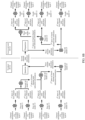
- FIG. 6B further shows a process in which the access network device performs dequantization and decompression on the second channel state indication information by using the second decoder, to obtain four pieces of first channel state indication information.
- the second decoder includes three third AI models, and a 3 rd third AI model to a 1 st AI model are sequentially denoted as a third AI model 23, a third AI model 22, and a third AI model 21. It may be understood that the third AI model 23 matches the second AI model 23, the third AI model 22 matches the second AI model 22, and the third AI model 21 matches the second AI model 21.
- an input of the third AI model 23 includes the second channel state indication information
- an output of the third AI model 23 includes a 2 nd piece of fourth channel state indication information and the 4 th piece of first channel state indication information.
- An input of the third AI model 22 includes the 2 nd piece of fourth channel state indication information
- an output of the third AI model 22 includes the 1 st piece of fourth channel state indication information and the 3 rd piece of first channel state indication information.
- An input of the third AI model 21 includes the 1 st piece of fourth channel state indication information
- an output of the third AI model 21 includes the 1 st piece of first channel state indication information and the 2 nd piece of first channel state indication information.
- an input of the third AI model 22 includes the second channel state indication information, and an output of the third AI model 22 includes the 1 st piece of fourth channel state indication information and the N th piece of first channel state indication information.
- An input of the third AI model 21 includes the 1 st piece of fourth channel state indication information, and an output of the third AI model 21 includes the first N-1 pieces of first channel state indication information in the N pieces of first channel state indication information.
- FIG. 6C further shows a process in which the access network device dequantizes and decompresses the second channel state indication information by using the second decoder, to obtain four pieces of first channel state indication information.
- the second decoder includes two third AI models, and a 2 nd third AI model and a 1 st AI model are sequentially denoted as the third AI model 22 and the third AI model 21. It may be understood that the third AI model 22 matches the second AI model 22, and the third AI model 21 matches the second AI model 21.
- the input of the third AI model 22 includes the second channel state indication information
- the output of the third AI model 22 includes the 1 st piece of fourth channel state indication information and the 4 th piece of first channel state indication information.
- the input of the third AI model 21 includes the 1 st piece of fourth channel state indication information
- the output of the third AI model 21 includes the 1 st piece of first channel state indication information, the 2 nd piece of first channel state indication information, and the 3 rd piece of first channel state indication information.
- K may be 2 or 3, that is, the second decoder may include two third AI models or three third AI models.
- the case in which the second decoder includes two third AI models may be understood with reference to the example in which N is 4.
- the case in which the second decoder includes three third AI models may be understood according to the following content.
- the input of the third AI model 23 includes the second channel state indication information
- the output of the third AI model 23 includes a 5 th piece of first channel state indication information in five pieces of first channel state indication information, the 2 nd piece of fourth channel state indication information, and the 1 st piece of fourth channel state indication information.
- the input of the third AI model 22 includes the 2 nd piece of fourth channel state indication information
- the output of the third AI model 22 includes the 3 rd piece of first channel state indication information and the 4 th piece of first channel state indication information in the five pieces of first channel state indication information.
- the input of the third AI model 21 includes the 1 st piece of fourth channel state indication information
- the output of the third AI model 21 includes the 1 st piece of first channel state indication information and the 2 nd piece of first channel state indication information in the five pieces of first channel state indication information.
- the second decoder is also correspondingly preconfigured as a corresponding structure.
- the structure of the second encoder is preconfigured in Manner 21
- the structure of the second decoder is also preconfigured in Manner 31
- the structure of the second encoder is preconfigured in Manner 22
- the structure of the second decoder is also preconfigured in Manner 32
- the structure of the second decoder is also preconfigured in Manner 33.
- the second decoder corresponds to the quantity of downlink transport layers.
- the terminal device does not need to indicate the value of N, and the access network device may learn of the value of N, so that the access network device may obtain the second decoder with reference to a preconfiguration manner and the quantity N of downlink transport layers.
- the access network device may determine the quantity N of downlink transport layers based on the value of the rank, so that the access network device may obtain the second decoder with reference to a preconfiguration manner and the quantity N of downlink transport layers.
- the access network device may determine a quantity of input ports of the second encoder and a quantity of output ports of the second decoder based on the value of N.
- the access network device may determine a corresponding second AI model based on the value of N.
- the access network device may determine a corresponding third AI model based on the value of N.
- the access network device may determine, based on the value of N, a quantity of second AI models included in the second encoder and a quantity of third AI models included in the second decoder. If the model type and the model parameter of each second AI model are preconfigured, the access network device may determine the second encoder and the second decoder based on the value of N.
- the access network device may determine, based on the value of N, the quantity K of second AI models included in the second encoder. If model types and model parameters of the K second AI models are preconfigured, the access network device may determine the structure of the second encoder based on a value of K, and correspondingly determine, by using the value of K, the second decoder matching the second encoder.
- the access network device may determine the quantity N of downlink transport layers based on the information, so that the access network device may obtain the second decoder with reference to a preconfiguration manner and the quantity N of downlink transport layers.
- the access network device determines the channel information of the N downlink transport layers by using the first decoder and the N pieces of first channel state indication information input into the first decoder.
- the first decoder is a decoder used together with the first encoder described in S502, and implementation of the first decoder may be understood as an inverse process of the first encoder.
- the access network device may determine the first decoder based on the information sent by the terminal device or a related configuration of the first encoder, and then the access network device inputs the N pieces of first channel state indication information determined in S505 into the first decoder, to obtain the channel information of the N downlink transport layers. It may be understood that in an example, in Solution 1, the first decoder has a dequantization function and a decompression function, and processing performed by the access network device on the N pieces of first channel state indication information by using the first decoder includes dequantization and decompression.
- the first decoder may be obtained through training in the foregoing training process.
- the first decoder also has three corresponding structures.
- the following shows three possible structures of the first decoder by using Manner 41 to Manner 43.
- Manner 41 matches the first encoder described in Manner 11
- Manner 42 matches the first encoder described in Manner 12
- Manner 43 matches the first encoder described in Manner 13.
- the first decoder includes one fourth AI model.
- the terminal device may process the N pieces of first channel state indication information by using the one fourth AI model, to restore the channel information of the N downlink transport layers. It may be understood that the access network device inputs the N pieces of first channel state indication information into the one fourth AI model. Correspondingly, an output of the first decoder includes the restored channel information of the N downlink transport layers. Optionally, the access network device may input the N pieces of first channel state indication information in parallel or serial into the one fourth AI model. This is not limited in this disclosure.
- different first decoders may be set for different quantities of downlink transport layers.
- the one fourth AI model included in the first decoder is associated with the value of N, and different values of N are associated with different fourth AI models.
- N the first decoder is denoted as a decoder 21 or a decoder in the AE model 21; or when N is 3, the first decoder is denoted as a decoder 31 or a decoder in the AE model 31.
- Such a design can enhance the AI model application flexibility.
- it is optionally set that a same first decoder or a decoder in a same AE model is correspondingly used for different quantities of downlink transport layers. This design can reduce the AI model storage overheads.
- the first decoder may include N fourth AI models, and an i th fourth AI model in the first decoder is used to process the i th piece of first channel state indication information in the N pieces of first channel state indication information, to obtain the channel information of the i th downlink transport layer in the N downlink transport layers. It may be understood that the N pieces of first channel state indication information are respectively input into the N fourth AI models. An input of the i th fourth AI model in the N fourth AI models includes the i th piece of first channel state indication information in the N pieces of first channel state indication information, and an output of the i th fourth AI model includes the channel information of the i th downlink transport layer.
- the N fourth AI models in the first decoder may be the same.
- model types (for example, used neural networks) of the N fourth AI models are the same, while model parameters are different.
- both model types and model parameters of the N fourth AI models are different. This is not limited in this disclosure.
- the first decoder includes M fourth AI models, and M is an integer greater than 1 and less than N.
- One fourth AI model may be used to process some (one or more pieces of) first channel state indication information in the N pieces of first channel state indication information. Alternatively, it may be described that some first channel state indication information in the N pieces of first channel state indication information may be processed by a same fourth AI model. Some first channel state indication information in the N pieces of first channel state indication information is input in serial or parallel into one of the M fourth AI models.
- the first decoder includes four fourth AI models, that is, a fourth AI model 11 associated with the first AI model 11, a fourth AI model 12 associated with the first AI model 12, a fourth AI model 13 associated with the first AI model 13, and a fourth AI model 14 associated with the first AI model 14.
- An input of the fourth AI model 11 includes the 1 st piece of first channel state indication information
- an output of the fourth AI model 11 includes the channel information of the downlink transport layer 1.
- the first decoder is also correspondingly preconfigured as a corresponding structure.
- the structure of the first encoder is preconfigured in Manner 11, the structure of the first decoder is also preconfigured in Manner 41; if the structure of the first encoder is preconfigured in Manner 12, the structure of the first decoder is also preconfigured in Manner 42; or if the structure of the first encoder is preconfigured in Manner 13, the structure of the first decoder is also preconfigured in Manner 43.
- the first decoder corresponds to the quantity of downlink transport layers.
- the terminal device does not need to indicate the value of N, and the access network device may learn of the value of N, so that the access network device may obtain the first decoder with reference to a preconfiguration manner and the quantity N of downlink transport layers.
- the access network device may determine the quantity N of downlink transport layers based on the value of the rank, so that the access network device may obtain the first decoder with reference to a preconfiguration manner and the quantity N of downlink transport layers.
- the access network device may determine a corresponding fourth AI model based on the value of N.
- the access network device may determine, based on the value of N, a quantity of first AI models included in the first encoder. If a model type and a model parameter of each first AI model are preconfigured, the access network device may obtain the first encoder based on the value of N.
- the access network device may further determine, based on the value of N, a quantity of fourth AI models included in the first decoder. If a model type and a model parameter of each fourth AI model are preconfigured, the access network device may obtain the first decoder based on the value of N.
- the structure of the first encoder is preconfigured in Manner 13
- M is N-2
- the access network device may determine, based on the value of N, the quantity M of first AI models included in the first encoder and the quantity M of fourth AI models included in the first decoder. If model types and model parameters of the M first AI models/fourth AI models are preconfigured, the access network device may obtain the first encoder and the first decoder based on a value of M.
- the access network device may integrate the restored channel information of the N downlink transport layers, to restore the foregoing downlink channel information estimated based on measurement of the downlink reference signal.
- compression is performed twice on the downlink channel information by using a plurality of levels of AI models, so that resources occupied by common information in CSI of a plurality of layers are reduced, and CSI feedback overheads can be reduced.
- FIG. 7 shows a communication method.
- the method mainly includes the following procedure.
- a terminal device determines channel information of N downlink transport layers, where N is a positive integer.
- the terminal device determines N pieces of first channel state indication information by using a first encoder and the channel information of the N downlink transport layers input into the first encoder.
- the terminal device may send the N pieces of first channel state indication information to an access network device.
- the terminal device may perform quantization processing on the N pieces of first channel state indication information, and send the N pieces of first channel state indication information to an access network device.
- the terminal device further performs the following S703 and S704 after performing S702.
- the second encoder has a compression (encoding) function but not a quantization function.
- the terminal device may perform compression processing on the N pieces of first channel state indication information by using the second encoder, to obtain the third channel state indication information.
- An input of the second encoder includes the N pieces of first channel state indication information
- an output of the second encoder includes the third channel state indication information.
- the third channel state indication information obtained in S703 is a compression of the N pieces of first channel state indication information obtained in S702.
- the third channel state indication information may also be understood as a sequence, and a sequence length corresponding to the third channel state indication information is less than a sum of sequence lengths corresponding to the N pieces of first channel state indication information.
- the second encoder in Solution 2 has the compression function but not the quantization function, and processing on the N pieces of first channel state indication information includes compression.
- the sequence corresponding to the third channel state indication information may be specifically a bit sequence.
- the second encoder may be obtained through training in the foregoing training process.
- a structure of the second encoder refer to any one of the following Manner 21-1, Manner 22-1, or Manner 23-1.
- the second encoder includes one second AI model.
- the terminal device may perform compression processing on the N pieces of first channel state indication information by using the one second AI model, to obtain the third channel state indication information. It may be understood that an input of the one second AI model includes the N pieces of first channel state indication information, and an output of the one second AI model includes the third channel state indication information.
- FIG. 8A is a schematic flowchart of encoding.
- FIG. 8A refers to the descriptions of FIG. 6A .
- a difference between FIG. 8A and FIG. 6A lies in that the second encoder does not have the quantization function, and an output of the second encoder is the third channel state indication information.
- the third channel state indication information is unquantized, and second channel state indication information is quantized information.
- the second encoder may include a plurality of second AI models, and a quantity of second AI models in the second encoder is related to the quantity N of downlink transport layers.
- FIG. 8B is a schematic flowchart of encoding.
- the second encoder does not have the quantization function, and an output of the second encoder is the third channel state indication information.
- the third channel state indication information is unquantized, and second channel state indication information is quantized information.
- the second encoder may include K second AI models.
- K is a positive integer greater than 1 and less than N-1.
- K is 2. It may be understood that some first channel state indication information in the N pieces of first channel state indication information is input in parallel into one second artificial intelligence AI model in the K second artificial intelligence AI models.
- FIG. 8C is a schematic flowchart of encoding. For descriptions of FIG. 8C , refer to the descriptions of FIG. 6C .
- a difference between FIG. 8C and FIG. 6C lies in that the second encoder does not have the quantization function, and an output of the second encoder is the third channel state indication information.
- the third channel state indication information is unquantized, and second channel state indication information is quantized information.
- S704 The terminal device performs quantization processing on the third channel state indication information to obtain the second channel state indication information.
- the to-be-quantized amount is the third channel state indication information
- an index output by querying the quantization dictionary is included in quantized information of the third channel state indication information, that is, the second channel state indication information.
- the third channel state indication information is a floating-point number sequence
- the second channel state indication information obtained through quantization may be specifically a bit sequence.
- FIG. 8A , FIG. 8B , and FIG. 8C further show a process in which the terminal device performs quantization processing on the third channel state indication information based on the quantizer, to obtain the second channel state indication information.
- An input of the quantizer includes the third channel state indication information
- an output of the quantizer includes the second channel state indication information.
- the terminal device may also quantize the N pieces of first channel state indication information in S702, so that the N pieces of first channel state indication information used by the terminal device in S703 are quantized information.
- the terminal device may separately perform quantization processing on the N pieces of first channel state indication information in S702 by using N quantizers.
- the N quantizers are in one-to-one correspondence with the N pieces of first channel state indication information.
- the N quantizers may be the same or different.
- the quantizer used by the terminal device may be preconfigured.
- the quantizer is preconfigured through definition by using a protocol, or the terminal device and the access network device negotiate about the quantizer in advance.
- the terminal device may determine the quantizer used by the terminal device, and send, to the access network device, information indicating the quantizer used by the terminal device.
- S705 The terminal device sends the second channel state indication information to the access network device.
- S706 The access network device performs dequantization processing on the second channel state indication information to obtain the third channel state indication information.
- FIG. 8A , FIG. 8B , and FIG. 8C further show a process in which the access network device performs dequantization processing on the second channel state indication information by using a dequantizer, to obtain the third channel state indication information.
- the dequantizer is used together with the quantizer.
- the dequantizer may be understood as performing an inverse operation of the quantizer.
- An input of the dequantizer includes the second channel state indication information, and an output of the dequantizer includes the third channel state indication information.
- the dequantizer is also preconfigured.
- the access network device may determine a matching dequantizer based on the information indicating the quantizer.
- the access network device determines the N pieces of first channel state indication information by using a second decoder and the third channel state indication information input into the second decoder.
- the second decoder is a decoder used together with the second encoder described in S703, and implementation of the second decoder may be understood as an inverse process of the second encoder.
- the access network device may determine the second decoder based on the information sent by the terminal device or a related configuration of the second encoder, and then the access network device inputs the received third channel state indication information into the second decoder, to obtain the N pieces of first channel state indication information. It may be understood that in an example, in Solution 2, the second decoder has only a decompression function, and processing performed by the access network device on the third channel state indication information by using the second decoder includes decompression.
- the second decoder includes one third AI model.
- An input of the second decoder includes the third channel state indication information determined by the access network device in S706, and an output of the one second decoder includes the N pieces of first channel state indication information.
- FIG. 8A further shows a process in which the access network device decompresses the third channel state indication information by using the second decoder, to obtain the N pieces of first channel state indication information.
- the second decoder may include a plurality of third AI models, and a quantity of third AI models in the second decoder is related to the quantity N of downlink transport layers.
- FIG. 8B further shows a process in which the access network device decompresses the third channel state indication information by using the second decoder, to obtain four pieces of first channel state indication information.
- the access network device decompresses the third channel state indication information by using the second decoder, to obtain four pieces of first channel state indication information.
- FIG. 8B A difference between FIG. 8B and FIG. 6B lies only in that the second channel state indication information is decompressed in FIG. 6B .
- the second decoder may include K third AI models.
- K is a positive integer greater than 1 and less than N-1.
- K is 2.
- FIG. 8C further shows a process in which the access network device decompresses the third channel state indication information by using the second decoder, to obtain four pieces of first channel state indication information.
- the access network device decompresses the third channel state indication information by using the second decoder, to obtain four pieces of first channel state indication information.
- FIG. 8C A difference between FIG. 8C and FIG. 6C lies only in that the second channel state indication information is decompressed in FIG. 6C .
- the access network device determines the channel information of the N downlink transport layers by using a first decoder and the N pieces of first channel state indication information input into the first decoder.
- An input of the fourth AI model 12 includes a 2 nd piece of first channel state indication information, and an output of the fourth AI model 12 includes channel information of a downlink transport layer 2.
- An input of the fourth AI model 13 includes a 3 rd piece of first channel state indication information, and an output of the fourth AI model 13 includes channel information of a downlink transport layer 3.
- An input of the fourth AI model 14 includes a 4 th piece of first channel state indication information, and an output of the fourth AI model 14 includes channel information of a downlink transport layer 4.
- the access network device may integrate restored channel information of the N downlink transport layers, to restore foregoing downlink channel information estimated based on measurement of a downlink reference signal.
- compression is performed twice on the downlink channel information by using a plurality of levels of AI models, so that resources occupied by common information in CSI of a plurality of layers are reduced.
- Quantization processing is performed on compressed channel state indication information, so that CSI feedback overheads can be reduced.
- an encoder and a decoder are used together, or a decoder but not an encoder is used.
- the encoder has a quantization function, and the decoder has a dequantization function; the encoder does not have a quantization function, and the decoder does not have a dequantization function; the encoder has a quantization function, and the decoder does not have a dequantization function; or the encoder does not have a quantization function, and the decoder has a dequantization function.
- the encoder does not have a quantization function, and the decoder has a dequantization function.
- the foregoing Solution 1 and Solution 2 may be implemented together.
- the second encoder and the second decoder that are used together the second encoder has the quantization function, and the second decoder does not have the dequantization function.
- S501 to S504 in Solution 1 are performed first, and then S706 to S708 in Solution 2 are performed.
- the second encoder does not have the quantization function, and the second decoder has the dequantization function.
- S701 to S705 in Solution 2 are performed first, and then S505 to S506 in Solution 1 are performed.
- functions of the first encoder and the second encoder in FIG. 5 or FIG. 7 are implemented by a same AI model W1, and/or functions of the first decoder and the second decoder are implemented by a same AI model W2 corresponding to the AI model W1.
- the AI model W1 and the AI model W2 are used and trained together.
- a specific training process is similar to the described joint training of the first encoder, the second encoder, the first decoder, and the second decoder, and details are not described herein again.
- An input of the AI model W1 is channel information of N downlink transport layers, and an output of the AI model W1 is second channel state indication information.
- An input of the AI model W2 is the second channel state indication information, and an output of the AI model W2 is the channel information of the N downlink transport layers.
- a range of a sequence length of the second channel state indication information corresponds to the AI model WI and/or the AI model W2, and/or corresponds to the value of N, that is, the range of the sequence length of the second channel state indication information may indicate the AI model WI and/or the AI model W2, and/or the value of N.
- the access network device may determine to perform decoding processing on the received second channel state indication information by using the AI model W2 matching the AI model W1 used by the terminal device.
- the AI model W1 and the AI model W2 may be trained together for any N, that is, are not dedicated to a specific N.
- a value of N may be included in the channel information of the N downlink transport layers.
- compressed transmission of channel information of a plurality of downlink transport layers may also be implemented.
- the communication apparatus 1000 includes a processing module 1001 and a communication module 1002.
- the communication apparatus 1000 may be a terminal device, or may be a communication apparatus that is used in a terminal device or used together with a terminal device and that can implement a communication method performed on a terminal device side.
- the communication apparatus 1000 may be an access network device, or may be a communication apparatus that is used in an access network device or used together with an access network device and that can implement a communication method performed on an access network device side.
- the communication module may also be referred to as a transceiver module, a transceiver, a transceiver machine, a transceiver apparatus, or the like.
- the processing module may also be referred to as a processor, a processing board, a processing unit, a processing apparatus, or the like.
- the communication module is configured to perform a sending operation and a receiving operation on the terminal device side or the access network device side in the foregoing method.
- a component configured to implement a receiving function in the communication module may be considered as a receiving unit, and a component configured to implement a sending function in the communication module may be considered as a sending unit.
- the communication module includes the receiving unit and the sending unit.
- the processing module 1001 may be configured to implement a processing function of the terminal device in the examples in FIG. 5 to FIG. 9
- the communication module 1002 may be configured to implement receiving and sending functions of the terminal device in the examples in FIG. 5 to FIG. 9 .
- the communication apparatus may be understood with reference to the third aspect and the possible designs in the third aspect in the summary.
- the processing module 1001 may be configured to implement a processing function of the access network device in the examples in FIG. 5 to FIG. 9
- the communication module 1002 may be configured to implement receiving and sending functions of the access network device in the examples in FIG. 5 to FIG. 9
- the communication apparatus may be understood with reference to the fourth aspect and the possible designs in the fourth aspect in the summary.
- the communication module and/or the processing module may be implemented by using a virtual module.
- the processing module may be implemented by using a software functional unit or a virtual apparatus, and the communication module may be implemented by using a software function or a virtual apparatus.
- the processing module or the communication module may be implemented by using a physical apparatus.
- the apparatus is implemented by using a chip/chip circuit
- the communication module may be an input/output circuit and/or a communication interface, and performs an input operation (corresponding to the foregoing receiving operation) and an output operation (corresponding to the foregoing sending operation); and the processing module is an integrated processor, a microprocessor, or an integrated circuit.
- Division into the modules in this disclosure is an example, and is merely division into logical functions. There may be another division manner during actual implementation.
- functional modules in examples of this disclosure may be integrated into one processor, each of the modules may exist alone physically, or two or more modules may be integrated into one module.
- the integrated module may be implemented in a form of hardware, or may be implemented in a form of a software functional module.
- this disclosure further provides a communication apparatus 1100.
- the communication apparatus 1100 may be a chip or a chip system.
- the chip system may include a chip, or may include a chip and another discrete component.
- the communication apparatus 1100 may be configured to implement a function of any network element in the communication system described in the foregoing examples.
- the communication apparatus 1100 may include at least one processor 1110.
- the processor 1110 is coupled to a memory.
- the memory may be located in the apparatus. Alternatively, the memory may be integrated with the processor. Alternatively, the memory may be located outside the apparatus.
- the communication apparatus 1100 may further include at least one memory 1120.
- the memory 1120 stores a computer program, a computer program or instructions, and/or data necessary for implementing any one of the foregoing examples.
- the processor 1110 may execute the computer program stored in the memory 1120, to complete the method in any one of the foregoing examples.
- the communication apparatus 1100 may further include a communication interface 1130, and the communication apparatus 1100 may exchange information with another device through the communication interface 1130.
- the communication interface 1130 may be a transceiver, a circuit, a bus, a module, a pin, or a communication interface of another type.
- the communication interface 1130 in the apparatus 1100 may alternatively be an input/output circuit, and may input information (or referred to as receiving information) and output information (or referred to as sending information).
- the processor is an integrated processor, a microprocessor, an integrated circuit, or a logic circuit. The processor may determine output information based on input information.
- Couplings in this disclosure are indirect couplings or communication connections between apparatuses, units, or modules, and may be electrical, mechanical, or in another form, and are used for information exchange between the apparatuses, the units, and the modules.
- the processor 1110 may operate cooperatively with the memory 1120 and the communication interface 1130.
- a specific connection medium between the processor 1110, the memory 1120, and the communication interface 1130 is not limited in this disclosure.
- the processor 1110, the memory 1120, and the communication interface 1130 are connected to each other through a bus 1140.
- the bus 1140 may be a peripheral component interconnect (peripheral component interconnect, PCI) bus, an extended industry standard architecture (extended industry standard architecture, EISA) bus, or the like.
- PCI peripheral component interconnect
- EISA extended industry standard architecture
- the bus may be classified into an address bus, a data bus, a control bus, and the like. For ease of representation, only one bold line is used to represent the bus in FIG. 11 , but this does not mean that there is only one bus or only one type of bus.
- the processor may be a general-purpose processor, a digital signal processor, an application-specific integrated circuit, a field programmable gate array or another programmable logic device, a discrete gate or a transistor logic device, or a discrete hardware component, and may implement or perform methods, steps, and logical block diagrams that are disclosed in this disclosure.
- the general-purpose processor may be a microprocessor, any conventional processor, or the like. The steps of the methods disclosed with reference to this disclosure may be directly implemented by a hardware processor, or may be implemented by a combination of hardware and a software module in the processor.
- the memory may be a non-volatile memory, for example, a hard disk drive (hard disk drive, HDD) or a solid-state drive (solid-state drive, SSD), or may be a volatile memory (volatile memory), for example, a random access memory (random access memory, RAM).
- the memory is any other medium that can carry or store expected program code in a form of an instruction or a data structure and that can be accessed by a computer, but is not limited thereto.
- the memory in this disclosure may alternatively be a circuit or any other apparatus that can implement a storage function, and is configured to store program instructions and/or data.
- the communication apparatus 1100 may be used in a terminal device.
- the communication apparatus 1100 may be the terminal device, or may be an apparatus that can support the terminal device in implementing functions of the terminal device in any one of the foregoing examples.
- the memory 1120 stores a computer program (or instructions) and/or data for implementing the functions of the terminal device in any one of the foregoing examples.
- the processor 1110 may execute the computer program stored in the memory 1120, to complete the method performed by the terminal device in any one of the foregoing examples.
- the communication interface in the communication apparatus 1100 may be configured to interact with an access network device, and send information to the access network device or receive information from the access network device.
- the communication apparatus 1100 provided in this example may be used in the access network device to complete the method performed by the access network device, or may be used in the terminal device to complete the method performed by the terminal device. Therefore, for technical effects that can be achieved by the communication apparatus 1100, refer to the foregoing method examples. Details are not described herein again.
- this disclosure provides a communication system, including an access network device and a terminal device.
- the access network device and the terminal device can implement the communication methods provided in the examples shown in FIG. 5 to FIG. 9 .
- All or some of the technical solutions provided in this disclosure may be implemented by software, hardware, firmware, or any combination thereof.
- software is used to implement the technical solutions, all or a part of the technical solutions may be implemented in a form of a computer program product.
- the computer program product includes one or more computer instructions.
- the computer may be a general-purpose computer, a dedicated computer, a computer network, a terminal device, an access network device, or another programmable apparatus.
- the computer instructions may be stored in a computer-readable storage medium, or may be transmitted from a computer-readable storage medium to another computer-readable storage medium.
- mutual reference can be made between examples.
- mutual reference can be made between methods and/or terms in method embodiments
- mutual reference can be made between functions and/or terms in apparatus embodiments
- mutual reference can be made between functions and/or terms in apparatus examples and method examples.
Landscapes
- Engineering & Computer Science (AREA)
- Computer Networks & Wireless Communication (AREA)
- Signal Processing (AREA)
- Quality & Reliability (AREA)
- Physics & Mathematics (AREA)
- Mathematical Physics (AREA)
- Compression, Expansion, Code Conversion, And Decoders (AREA)
- Mobile Radio Communication Systems (AREA)
Applications Claiming Priority (2)
| Application Number | Priority Date | Filing Date | Title |
|---|---|---|---|
| CN202210800531.3A CN117411526A (zh) | 2022-07-06 | 2022-07-06 | 一种通信方法及装置 |
| PCT/CN2023/105001 WO2024008004A1 (zh) | 2022-07-06 | 2023-06-30 | 一种通信方法及装置 |
Publications (2)
| Publication Number | Publication Date |
|---|---|
| EP4539351A1 true EP4539351A1 (de) | 2025-04-16 |
| EP4539351A4 EP4539351A4 (de) | 2025-10-08 |
Family
ID=89454790
Family Applications (1)
| Application Number | Title | Priority Date | Filing Date |
|---|---|---|---|
| EP23834771.0A Pending EP4539351A4 (de) | 2022-07-06 | 2023-06-30 | Kommunikationsverfahren und -vorrichtung |
Country Status (4)
| Country | Link |
|---|---|
| US (1) | US20250141525A1 (de) |
| EP (1) | EP4539351A4 (de) |
| CN (1) | CN117411526A (de) |
| WO (1) | WO2024008004A1 (de) |
Families Citing this family (4)
| Publication number | Priority date | Publication date | Assignee | Title |
|---|---|---|---|---|
| US20240275557A1 (en) * | 2023-02-14 | 2024-08-15 | Qualcomm Incorporated | Layer-specific accuracy for channel state feedback |
| WO2025175475A1 (en) * | 2024-02-20 | 2025-08-28 | Nokia Shanghai Bell Co., Ltd. | Model framework |
| CN120729481A (zh) * | 2024-03-30 | 2025-09-30 | 华为技术有限公司 | 通信方法及装置 |
| WO2026039967A1 (zh) * | 2024-08-19 | 2026-02-26 | Oppo广东移动通信有限公司 | Csi反馈方法、第一设备和第二设备 |
Family Cites Families (4)
| Publication number | Priority date | Publication date | Assignee | Title |
|---|---|---|---|---|
| EP3935743A1 (de) * | 2019-03-08 | 2022-01-12 | FRAUNHOFER-GESELLSCHAFT zur Förderung der angewandten Forschung e.V. | Csi-meldung und codebuchstruktur zur auf doppler-delay-codebuch basierenden vorcodierung in einem drahtloskommunikationssystem |
| CN110350958B (zh) * | 2019-06-13 | 2021-03-16 | 东南大学 | 一种基于神经网络的大规模mimo的csi多倍率压缩反馈方法 |
| CN116260494A (zh) * | 2021-12-10 | 2023-06-13 | 中兴通讯股份有限公司 | 反馈、获取及训练方法、终端、基站、电子设备和介质 |
| CN116193504B (zh) * | 2023-04-18 | 2023-07-21 | 南京云程半导体有限公司 | 一种信道状态信息的上报方法、电子设备及存储介质 |
-
2022
- 2022-07-06 CN CN202210800531.3A patent/CN117411526A/zh active Pending
-
2023
- 2023-06-30 WO PCT/CN2023/105001 patent/WO2024008004A1/zh not_active Ceased
- 2023-06-30 EP EP23834771.0A patent/EP4539351A4/de active Pending
-
2025
- 2025-01-03 US US19/009,306 patent/US20250141525A1/en active Pending
Also Published As
| Publication number | Publication date |
|---|---|
| CN117411526A (zh) | 2024-01-16 |
| WO2024008004A1 (zh) | 2024-01-11 |
| EP4539351A4 (de) | 2025-10-08 |
| US20250141525A1 (en) | 2025-05-01 |
Similar Documents
| Publication | Publication Date | Title |
|---|---|---|
| EP4539351A1 (de) | Kommunikationsverfahren und -vorrichtung | |
| EP4391474A1 (de) | Kommunikationsverfahren und -vorrichtung | |
| CN118118133A (zh) | 一种通信方法及装置 | |
| EP4447334A1 (de) | Uplink-vorcodierungsverfahren und -vorrichtung | |
| EP4661464A1 (de) | Kommunikationsverfahren und -vorrichtung | |
| EP4447524A1 (de) | Kommunikationsverfahren und -vorrichtung | |
| EP4529035A1 (de) | Kommunikationsverfahren und -vorrichtung | |
| CN116260552A (zh) | 一种csi发送和接收方法及装置 | |
| WO2024046419A1 (zh) | 一种通信方法及装置 | |
| WO2024169757A1 (zh) | 一种通信的方法和通信装置 | |
| US20250202560A1 (en) | Communication method and apparatus | |
| EP4478619A1 (de) | Kommunikationsverfahren und -vorrichtung | |
| JP2026513338A (ja) | 通信方法及び通信装置 | |
| US20260031882A1 (en) | Compressed information feedback method and apparatus | |
| US20250088258A1 (en) | Model application method and apparatus | |
| CN121770571A (zh) | 通信方法和通信装置 | |
| CN122001423A (zh) | 通信方法和装置 | |
| WO2025161853A1 (zh) | 模型监控方法及装置、系统 | |
| WO2025140663A1 (zh) | 模型数据获取方法及装置、系统 | |
| CN121508770A (zh) | 通信方法和装置 | |
| CN120934711A (zh) | 一种通信方法和通信装置 | |
| KR20250156584A (ko) | 무선 통신 시스템에서, ai 모델에 기반하여 채널 변화를 검출하기 위한 장치 및 방법 | |
| CN121771028A (zh) | 通信方法和通信装置 | |
| CN120785384A (zh) | 一种通信方法及相关装置 | |
| CN119172772A (zh) | 一种通信方法及装置 |
Legal Events
| Date | Code | Title | Description |
|---|---|---|---|
| STAA | Information on the status of an ep patent application or granted ep patent |
Free format text: STATUS: THE INTERNATIONAL PUBLICATION HAS BEEN MADE |
|
| PUAI | Public reference made under article 153(3) epc to a published international application that has entered the european phase |
Free format text: ORIGINAL CODE: 0009012 |
|
| STAA | Information on the status of an ep patent application or granted ep patent |
Free format text: STATUS: REQUEST FOR EXAMINATION WAS MADE |
|
| 17P | Request for examination filed |
Effective date: 20250109 |
|
| AK | Designated contracting states |
Kind code of ref document: A1 Designated state(s): AL AT BE BG CH CY CZ DE DK EE ES FI FR GB GR HR HU IE IS IT LI LT LU LV MC ME MK MT NL NO PL PT RO RS SE SI SK SM TR |
|
| A4 | Supplementary search report drawn up and despatched |
Effective date: 20250905 |
|
| RIC1 | Information provided on ipc code assigned before grant |
Ipc: H04B 7/0413 20170101AFI20250901BHEP Ipc: H04L 1/00 20060101ALI20250901BHEP Ipc: H04B 7/06 20060101ALI20250901BHEP |
|
| DAV | Request for validation of the european patent (deleted) | ||
| DAX | Request for extension of the european patent (deleted) |