EP4539373A1 - Kommunikationsverfahren, endgerätevorrichtung, netzwerkvorrichtung und kommunikationssystem - Google Patents
Kommunikationsverfahren, endgerätevorrichtung, netzwerkvorrichtung und kommunikationssystem Download PDFInfo
- Publication number
- EP4539373A1 EP4539373A1 EP23830011.5A EP23830011A EP4539373A1 EP 4539373 A1 EP4539373 A1 EP 4539373A1 EP 23830011 A EP23830011 A EP 23830011A EP 4539373 A1 EP4539373 A1 EP 4539373A1
- Authority
- EP
- European Patent Office
- Prior art keywords
- pdu
- pdu set
- terminal device
- network device
- indication information
- Prior art date
- Legal status (The legal status is an assumption and is not a legal conclusion. Google has not performed a legal analysis and makes no representation as to the accuracy of the status listed.)
- Pending
Links
Images




Classifications
-
- H—ELECTRICITY
- H04—ELECTRIC COMMUNICATION TECHNIQUE
- H04L—TRANSMISSION OF DIGITAL INFORMATION, e.g. TELEGRAPHIC COMMUNICATION
- H04L1/00—Arrangements for detecting or preventing errors in the information received
- H04L1/12—Arrangements for detecting or preventing errors in the information received by using return channel
- H04L1/16—Arrangements for detecting or preventing errors in the information received by using return channel in which the return channel carries supervisory signals, e.g. repetition request signals
- H04L1/18—Automatic repetition systems, e.g. Van Duuren systems
- H04L1/1829—Arrangements specially adapted for the receiver end
- H04L1/1848—Time-out mechanisms
-
- H—ELECTRICITY
- H04—ELECTRIC COMMUNICATION TECHNIQUE
- H04L—TRANSMISSION OF DIGITAL INFORMATION, e.g. TELEGRAPHIC COMMUNICATION
- H04L1/00—Arrangements for detecting or preventing errors in the information received
- H04L1/12—Arrangements for detecting or preventing errors in the information received by using return channel
- H04L1/16—Arrangements for detecting or preventing errors in the information received by using return channel in which the return channel carries supervisory signals, e.g. repetition request signals
- H04L1/1607—Details of the supervisory signal
- H04L1/1642—Formats specially adapted for sequence numbers
-
- H—ELECTRICITY
- H04—ELECTRIC COMMUNICATION TECHNIQUE
- H04L—TRANSMISSION OF DIGITAL INFORMATION, e.g. TELEGRAPHIC COMMUNICATION
- H04L1/00—Arrangements for detecting or preventing errors in the information received
- H04L1/12—Arrangements for detecting or preventing errors in the information received by using return channel
- H04L1/16—Arrangements for detecting or preventing errors in the information received by using return channel in which the return channel carries supervisory signals, e.g. repetition request signals
- H04L1/18—Automatic repetition systems, e.g. Van Duuren systems
- H04L1/1829—Arrangements specially adapted for the receiver end
- H04L1/1835—Buffer management
Definitions
- Embodiments of this application relate to the communication field, and specifically, to a communication method, a terminal device, a network device, and a communication system.
- Uplink scheduling performed by a network device on a terminal device is based on a scheduling request (scheduling request, SR) and a buffer status report (buffer status report, BSR) that are sent by the terminal device.
- the network device may learn, based on the SR, that the terminal device needs to perform transmission of uplink data, and may learn, based on the BSR, of an amount of data buffered in a buffer of the terminal device.
- a network device After receiving an uplink scheduling request, a network device schedules uplink data by using downlink control information (downlink control information, DCI). After receiving the scheduling DCI, a terminal device uploads the uplink data on a specified time-frequency resource. After receiving the uplink data, the network device does not immediately return an acknowledgment (acknowledgment, ACK) or a negative acknowledgment (negative acknowledgment, NACK) by using a HARQ at a MAC layer, to indicate whether the uplink data is successfully received. Therefore, the terminal device cannot instantly determine whether the uplink data is successfully uploaded. Consequently, the terminal device cannot determine a processing manner of data related to the uplink data. Further, uplink resources are not fully used, and a waste of the uplink resources is caused.
- DCI downlink control information
- NACK negative acknowledgment
- the terminal device considers by default that the uplink data #1 is successfully uploaded. However, actually, the uplink data #1 is not successfully uploaded, and the network device does not indicate to perform retransmission of the uplink data #1 only when a quantity of retransmission times of the uplink data #1 reaches an upper limit.
- the terminal device considers by default that the uplink data #1 is successfully uploaded, so that the terminal device may continue to upload uplink data #2 related to the uplink data #1 (for example, decoding of the uplink data #2 needs to depend on the uplink data #1). In this case, uploading the uplink data #2 by the terminal device causes the waste of the uplink resources.
- this application provides a communication method, so that the terminal device can determine whether the uplink data is successfully uploaded, to avoid the waste of the uplink resources caused by uploading the data when the data does not need to be uploaded.
- the communication method includes: A terminal device reports first indication information to a network device, where the first indication information indicates a second protocol data unit set (Protocol Data Unit set, PDU set) PDU set referenced (which may also be referred to as depended on) by a first PDU set; and the terminal device determines, based on at least one of a timeout status of a timer of the terminal device and a feedback status of the network device for the first indication information, whether the second PDU set is successfully uploaded.
- PDU set Protocol Data Unit set
- the first PDU set includes a PDU set to be sent by the terminal device
- the second PDU set includes a PDU set that has been sent by the terminal device
- the first PDU set references the second PDU set indicates that successful decoding of the first PDU set is premised on successful decoding of the second PDU set.
- the terminal device reports the indication information indicating the second PDU set that has been sent and that is referenced by the to-be-sent first PDU set, and after sending the first indication information, determines, based on at least one of the timeout status (for example, timing duration or whether the started timer expires) of the started timer and the feedback status (for example, delivering information in response to the first indication information) of the network device for the received first indication information, whether the second PDU set is successfully uploaded.
- the terminal device can determine whether the second PDU set is successfully uploaded.
- the terminal device can determine a processing manner of the first PDU set based on the determining result, to avoid a waste of uplink resources caused by uploading the first PDU set when the first PDU set does not need to be uploaded.
- the first indication information includes a media access control control element (media access control control element, MAC CE), and the MAC CE includes a logical channel identifier LCID and an identifier of the second PDU set.
- the LCID indicates a logical channel corresponding to the MAC CE, and the logical channel is for transmission of the identifier of the second PDU set referenced by the first PDU set.
- the method when it is determined that the second PDU set is not successfully uploaded, the method further includes: The terminal device discards the first PDU set.
- the terminal device when determining that the second PDU set is not successfully uploaded, the terminal device can determine that the first PDU set cannot be correctly parsed even if the first PDU set is uploaded. Therefore, the first PDU set does not need to be uploaded. Further, to save buffer space, the first PDU set may be discarded or deleted from a buffer.
- that the terminal device discards the first PDU set includes: After a first timer expires or when a first timer expires, if the first PDU set is buffered in a buffer of the terminal device, the terminal device discards the first PDU set in the buffer.
- the first timer is a discard timer set by the terminal device for the first PDU set
- a start moment of the first timer is a moment (which may also be referred to as a time point (time point)) at which a packet data convergence protocol (packet data convergence protocol, PDCP) entity of the terminal device receives a last bit of a last PDU in the first PDU set
- timing duration of the first timer is less than a frame arrival periodicity
- the frame arrival periodicity indicates an interval between arrival of two adjacent frames at the buffer.
- the PDCP entity of the terminal device may be understood as a transmission entity (which may also be referred to as a transmitting PDCP entity) at a PDCP layer of the terminal device.
- the method when it is determined that the second PDU set is successfully uploaded, the method further includes: The terminal device discards a part of PDUs in the first PDU set; or the terminal device sends the first PDU set.
- the terminal device when the terminal device determines that the second PDU set is successfully uploaded, the terminal device can indirectly learn that a PDU included in the first PDU set can be uploaded.
- a specific upload status needs to be determined based on scheduling of the network device. For example, the network device may successfully schedule only the part of PDUs in the first PDU set. For another example, the network device successfully schedules all PDUs in the first PDU set.
- subsequent processing on the first PDU set may be successfully sending the part of PDUs in the first PDU set or successfully sending all the PDUs in the first PDU set.
- the buffer of the terminal device includes a buffer at a radio link control (radio link control, RLC) layer of the terminal device or a buffer at a packet data convergence protocol (packet data convergence protocol, PDCP) layer of the terminal device.
- RLC radio link control
- PDCP packet data convergence protocol
- the buffer of the terminal device may be buffers at different protocol layers, so that flexibility of the solution is improved.
- that the terminal device determines, based on a timeout status of a timer of the terminal device, that the second PDU set is not successfully uploaded includes: The terminal device starts a second timer when sending the first indication information, and if the second timer expires and the terminal device does not receive scheduling information from the network device, the terminal device determines that the second PDU set is not successfully uploaded.
- the method further includes: When (when) or after (after) receiving the first PDU set generated by an application layer of the terminal device, a protocol layer entity of the terminal device performs header detection on the first PDU set, to determine an identifier of the first PDU set and an identifier of at least one PDU set referenced by the first PDU set.
- a protocol layer of the terminal device encapsulates the identifier of the first PDU set and the identifier of the at least one PDU set into a header of the protocol layer of the first PDU set.
- the first PDU set generated by the application layer includes the identifier of the first PDU set and the identifier of the at least one referenced PDU set.
- a communication method is provided.
- the method may be performed by a network device, or may be performed by a component (for example, a chip or a circuit) of the network device. This is not limited in this application.
- the following uses an example in which the network device performs the method for description.
- the communication method includes: A network device receives first indication information from a terminal device, where the first indication information indicates a second protocol data unit set PDU set referenced by a first PDU set.
- the network device determines not to schedule the first PDU set.
- the first PDU set includes a PDU set to be sent by the terminal device
- the second PDU set includes a PDU set that is referenced by the first PDU set and that has been sent by the terminal device
- the first PDU set references the second PDU set indicates that successful decoding of the first PDU set is premised on the successful decoding of the second PDU set.
- the first indication information refer to the descriptions of the first indication information in the first aspect. Details are not described herein again.
- the network device when the network device determines that the second PDU set is successfully received, the network device schedules the first PDU set.
- that the network device determines that not all PDUs needed for successful decoding of the second PDU set are successfully received includes: The network device determines that the network device does not store an identifier of the second PDU set.
- the method further includes: The network device receives the second PDU set from the terminal device, where the second PDU set includes third indication information.
- the network device determines, based on the third indication information, whether to store the identifier of the second PDU set.
- the third indication information refer to the descriptions of the third indication information in the first aspect. Details are not described herein again.
- the fifth indication information includes at least one of the following: identifiers of a 1 st PDU and a last PDU included in the third PDU set, a total quantity of PDUs included in the third PDU set, a quantity of successfully communicated PDUs needed for the successful decoding of the third PDU set, a ratio of a quantity of successfully communicated PDUs needed for the successful decoding of the third PDU set to a total quantity of PDUs included in the third PDU set, an identifier indicating that a PDU included in the third PDU set belongs to the third PDU set, or a sequence number of a PDU included in the third PDU set in the third PDU set.
- the network device may discard the some received PDUs.
- the terminal device can determine, based on the received fourth indication information, that a part of PDUs are not successfully communicated. For example, the terminal device determines that a PDU #1 is not successfully communicated, and the PDU #1 is a PDU in a PDU set #1. Therefore, it is determined that the terminal device determines that a PDU set that references the PDU set #1 may not need to be uploaded, or another PDU in the PDU set #1 may not need to be uploaded, so that the terminal device discards the PDU set or the PDU that does not need to be uploaded. This saves a buffer and uplink resources of the terminal device.
- the method before the terminal device receives third indication information from the network device, the method further includes: The terminal device sends the third PDU set to the network device, where the third PDU set includes fifth indication information, and the fifth indication information is provided for the network device, to be used as a basis for the network device to determine whether the third PDU set is successfully received.
- the terminal device sends the third PDU set to the network device, where the third PDU set includes fifth indication information, and the fifth indication information is provided for the network device, to be used as a basis for the network device to determine whether the third PDU set is successfully received.
- the fifth indication information refer to the descriptions of the fifth indication information in the third aspect. Details are not described herein again.
- the method further includes: Before or when the third PDU set is buffered into a buffer, the terminal device performs header detection on the third PDU set generated by an application layer, to determine an identifier of the third PDU set and an identifier of at least one PDU set referenced by the third PDU set.
- the terminal device encapsulates the identifier of the third PDU set and the identifier of the at least one PDU set into a header of a protocol layer of the third PDU set.
- the third PDU set generated by the application layer includes the identifier of the third PDU set and the identifier of the at least one PDU set.
- a 1 st PDU or each PDU in the third PDU set includes the identifier of the third PDU set and the identifier of the at least one PDU set, and the successful decoding of the third PDU set is premised on successful decoding of the at least one PDU set.
- the terminal device may learn, through the header detection, of an identifier of a PDU set and an identifier of another PDU set referenced by the PDU set, so that the terminal device learns of a reference relationship between different PDU sets.
- a terminal device configured to perform the method according to any one of the first aspect and the implementations of the first aspect, or any one of the fourth aspect and the implementations of the fourth aspect.
- the terminal device includes a processor and a memory.
- the memory is configured to store a computer program.
- the processor is configured to invoke the computer program from the memory and run the computer program, so that the terminal device performs the method according to any one of the first aspect and the implementations of the first aspect, or any one of the fourth aspect and the implementations of the fourth aspect.
- a network device configured to perform the method according to the second aspect or the third aspect.
- the network device includes a processor and a memory.
- the memory is configured to store a computer program.
- the processor is configured to invoke the computer program from the memory and run the computer program, so that the network device performs the method according to any one of the second aspect and the implementations of the second aspect, or any one of the third aspect and the implementations of the third aspect.
- the communication apparatus may be a chip, a chip system, or a circuit in the terminal device.
- the transceiver unit may be an input/output interface, an interface circuit, an output circuit, an input circuit, a pin, a related circuit, or the like on the chip, the chip system, or the circuit.
- the processing unit may be at least one processor, a processing circuit, a logic circuit, or the like.
- a communication apparatus configured to perform the method according to any one of the second aspect and the implementations of the second aspect, or any one of the third aspect and the implementations of the third aspect.
- the communication apparatus may include units and/or modules, for example, a processing unit and a transceiver unit, configured to perform the method according to any one of the second aspect and the implementations of the second aspect, or any one of the third aspect and the implementations of the third aspect.
- the communication apparatus is a network device.
- the transceiver unit may be a transceiver or an input/output interface
- the processing unit may be at least one processor.
- the transceiver may be a transceiver circuit.
- the input/output interface may be an input/output circuit.
- the transceiver unit may be an input/output interface, an interface circuit, an output circuit, an input circuit, a pin, a related circuit, or the like on the chip, the chip system, or the circuit.
- the processing unit may be at least one processor, a processing circuit, a logic circuit, or the like.
- this application provides a processor, configured to perform the methods according to the foregoing aspects.
- a computer-readable storage medium stores a computer program.
- the communication apparatus is enabled to perform the method according to any one of the implementations of the first aspect to the fourth aspect.
- a computer program product including instructions is provided.
- the computer program product runs on a computer, the computer is enabled to perform the method according to any one of the implementations of the first aspect to the fourth aspect.
- a chip includes a processor and a communication interface, and the processor reads, through the communication interface, instructions stored in a memory, to perform the method according to any one of the implementations of the first aspect to the fourth aspect.
- the chip further includes the memory.
- the memory stores a computer program or the instructions.
- the processor is configured to execute the computer program or the instructions stored in the memory. When the computer program or the instructions are executed, the processor is configured to perform the method according to any one of the implementations of the first aspect to the fourth aspect.
- a communication system including the terminal device in the fifth aspect and the network device in the sixth aspect.
- the technical solutions in embodiments of this application may be applied to various communication systems, for example, a 5th generation (5th generation, 5G) system or new radio (new radio, NR), a long term evolution (long term evolution, LTE) system, an LTE frequency division duplex (frequency division duplex, FDD) system, and an LTE time division duplex (time division duplex, TDD) system.
- 5G 5th generation
- NR new radio
- LTE long term evolution
- LTE frequency division duplex frequency division duplex
- FDD frequency division duplex
- TDD time division duplex
- the technical solutions provided in this application may be further applied to a future communication system, for example, a 6th generation mobile communication system.
- the technical solutions in embodiments of this application may be further applied to a device-to-device (device-to-device, D2D) communication, a vehicle-to-everything (vehicle-to-everything, V2X) communication, a machine-to-machine (machine-to-machine, M2M) communication, a machine type communication (machine type communication, MTC), or an internet of things (internet of things, IoT) communication system, or another communication system.
- D2D device-to-device
- V2X vehicle-to-everything
- V2X vehicle-to-everything
- M2M machine-to-machine
- MTC machine type communication
- IoT internet of things
- the terminal device may alternatively be a terminal device in an IoT system.
- the IoT is an important part in future development of information technologies.
- a main technical feature of the IoT is to connect things to a network by using a communication technology, to implement an intelligent network for human-machine interconnection and thing-thing interconnection.
- an IoT technology may implement massive connections, deep coverage, and terminal power saving by using, for example, a narrowband (narrowband, NB) technology.
- NB narrowband
- the communication system 100 may include at least one network device 101 and at least one of terminal devices 102 to 107.
- the terminal devices 102 to 107 may be mobile or fixed.
- the network device 101 may communicate with one or more of the terminal devices 102 to 107 through a radio link.
- Each network device may provide communication coverage for a particular geographical area, and may communicate with a terminal device located in the coverage area.
- the terminal devices may directly communicate with each other.
- direct communication between the terminal devices may be implemented by using a device-to-device (device-to-device, D2D) technology.
- D2D device-to-device
- direct communication may be performed between terminal devices 105 and 106 and between terminal devices 105 and 107 by using the D2D technology.
- the terminal device 106 and the terminal device 107 may separately or simultaneously communicate with the terminal device 105.
- the terminal devices 105 to 107 may separately communicate with the network device 101.
- the terminal devices 105 to 107 may directly communicate with the network device 101.
- the terminal devices 105 and 106 in the figure may directly communicate with the network device 101.
- the terminal devices 105 to 107 may indirectly communicate with the network device 101.
- the terminal device 107 in FIG. 1 communicates with the network device 101 through the terminal device 105.
- a plurality of antennas may be disposed for each communication device.
- the disposed plurality of antennas may include at least one transmit antenna configured to send a signal and at least one receive antenna configured to receive a signal. Therefore, communication devices in the communication system 100 may communicate with each other by using a multi-antenna technology.
- An interface between the network device and the terminal device may be a Uu interface (or referred to as an air interface). It is clear that in future communication, names of these interfaces may remain unchanged, or may be replaced by other names. This is not limited in this application.
- communication between the network device and the terminal device complies with a specific protocol layer structure.
- Network layering means that work such as sending, forwarding, packaging, or unpacking data of a network node (for example, the network device and the terminal device), and loading or unpacking control information is respectively implemented by different hardware and software modules. In this way, a complex problem of communication and network interconnection can be simplified.
- the protocol layer structure between the network device and the terminal device in embodiments of this application is briefly described with reference to FIG. 2 .
- network layer division of the network device and the terminal device includes an application layer, an RRC layer, an SDAP layer, a PDCP layer, an RLC layer, and a MAC layer.
- a main function of the application layer is to provide a plurality of services, such as a file server, a database service, an email, and another network software service, for application software.
- Functions implemented by the RRC layer include establishing, maintaining, and releasing an RRC connection, and allocating or reconfiguring a radio resource used for the RRC connection.
- One of functions of the SDAP layer is mapping between a quality of service (Quality of Service) flow and a data radio bearer (data radio bearer, DRB).
- the PDCP layer is responsible for compressing and decompressing an IP header, maintaining a PDCP layer sequence number, performing encryption and decryption, and the like.
- the RLC layer mainly provides a radio link control function, and provides services such as segmentation, retransmission control, and on-demand sending for an upper layer.
- Functions of the MAC layer include mapping between logical channels and transport channels, and selecting an appropriate transport format for each transport channel.
- FIG. 2 is merely an example, and does not constitute any limitation on the protection scope of this application.
- FIG. 1 is merely a simplified diagram of an example for ease of understanding.
- the communication system 100 may further include another network device or may further include another terminal device (not shown in FIG. 1 ).
- the communication system 100 may further include a core network device.
- An access network device provides a radio access connection for the terminal device, and may send data to the terminal device or receive data sent by the terminal device.
- the access network device is also connected to the core network device, and may forward, to the core network device, the data received from the terminal device, or receive, from the core network device, the data that needs to be sent to the terminal device.
- Extended reality Extended Reality
- the extended reality includes virtual reality (Virtual Reality, VR), augmented reality (Augmented Reality, AR), mixed reality (Mixed Reality, MR), and the like, and is one of the most attractive applications for a future 5G network.
- An XR application provides a virtual immersive world for a user by providing audio and video signals.
- Video frame transmission is classified into I-frame (I-frame) transmission and P-frame (P-frame) transmission.
- the I-frame may be referred to as an intra frame, is an independent frame that carries all information, and can be decoded independently without reference to another image.
- the P-frame may be referred to as a predicted frame.
- the P-frame is predicted from a P-frame or an I-frame before the P-frame, and the P-frame is compared with the P-frame or the I-frame before the P-frame to obtain difference information or data.
- inter-frame compression is performed by considering a motion characteristic.
- Protocol data unit (Protocol Data Unit, PDU): a specific data frame format indicates that a PDU is created at each layer of a transmission system in a hierarchical network structure.
- the PDU contains information from an upper layer and additional information from an entity at a current layer.
- the PDU is transmitted to a next lower layer.
- Protocol data unit set includes one or more PDUs, and is information about a unit generated by an application layer.
- the information about the unit may refer to a frame (frame) or a slice (slice) in an XR media service.
- the application layer needs to receive all PDUs in a PDU set to use the information about the unit. In some other applications, the application layer can restore a part or all of the information about the unit by receiving only a part of a PDU set.
- all the PDUs in the PDU set are processed as a whole. For example, a frame in a group of pictures (group of pictures, GoP) can be normally decoded only after all frames on which the frame depends are received and decoded. If the dependency between PDU sets is not considered, a randomly discarded data packet in a 5GS affects normal decoding of a subsequently communicated data packet, resulting in transmission of an invalid data packet and a radio waste.
- group of pictures group of pictures
- PDU set sequence number PDU set sequence number, PS-SN
- reference PDU set sequence number reference PDU set sequence number, RPS-SN
- a referenced PDU set may be referred to as a reference PDU set, and a PDU set that references the reference PDU set is referred to as a dependent PDU set.
- New data indicator new data indicator, NDI field and quantity of hybrid automatic repeat request (hybrid automatic repeat request, HARQ) processes: A 1-bit NDI field and a 4-bit HARQ process number in DCI (for example, DCI format 0_0, 0_1, or 0_2) for scheduling uplink data indicate whether a network device is scheduling re-communicated data or scheduling newly communicated data.
- DCI for example, DCI format 0_0, 0_1, or 0_2
- the NDI and the HARQ process number indicate whether the uploaded data is newly communicated or re-communicated. For a same HARQ process number, if an NDI indication value is the same as that in previous scheduling, this scheduling is retransmission of previously scheduled data; or if an NDI indication value is different from that in previous scheduling (a previous NDI indication value is 0, and the current NDI indication value is 1, or vice versa), this scheduling is new transmission. After receiving the NDI indicating new transmission, the terminal device refreshes a buffer of an associated HARQ process by using data that has not been communicated. If receiving the NDI indicating retransmission, the terminal device re-uploads data buffered in a buffer of a corresponding HARQ process.
- Uplink scheduling The network device schedules uplink data of the terminal device based on SR and BSR signaling sent by the terminal device.
- An SR is physical layer signaling.
- the terminal device may upload the SR to the network device by using a dedicated and periodic physical uplink control channel (physical uplink control channel, PUCCH).
- PUCCH physical uplink control channel
- the network device learns that the terminal device needs to perform transmission of the uplink data, and may allocate an uplink resource to the terminal device.
- the network device cannot determine an amount of data that needs to be communicated by the terminal device, and cannot determine a quantity of uplink resources that should be allocated to the terminal device. Therefore, subsequently, the terminal device still needs to send a BSR signal to the network device, to report an amount of data buffered in a buffer on a terminal device side, so as to apply for the uplink resources.
- example or “for example” is used to represent an example, an instance, or an illustration. Any embodiment or design scheme described as “example” or “for example” in this application should not be construed as being more preferred or advantageous than other embodiments or design schemes. To be precise, use of the word like “example” or “for example” is intended to present a relative concept in a specific manner.
- "store” in embodiments of this application may mean storing in one or more memories.
- the one or more memories may be separately disposed, or may be integrated into an encoder or a decoder, a processor, or a communication apparatus.
- some of the one or more memories may be separately disposed, and some of the one or more memories are integrated into the decoder, the processor, or the communication apparatus.
- a type of the memory may be a storage medium in any form. This is not limited in this application.
- control channel may include other physical layer control channels such as a PDCCH and an enhanced physical downlink control channel (enhanced physical downlink control channel, EPDCCH).
- PDCCH physical downlink control channel
- EPDCCH enhanced physical downlink control channel
- the downlink control channel is the physical downlink control channel PDCCH, but this does not constitute a limitation on embodiments of this application.
- the downlink control channel may also be defined as another term or concept, which is applicable to the technical solutions in embodiments of this application.
- the downlink control channel and the PDCCH may be alternately used, and the PDCCH may be considered as an example description of the uplink control channel.
- this application provides a communication method, to determine whether the uplink data is successfully uploaded, and avoid the waste of the uplink resources caused by scheduling the invalid frame.
- the communication method provided in embodiments of this application may be applied to a system in which communication is performed by using a multi-antenna technology, for example, a communication system 100 shown in FIG. 1 .
- the communication system may include at least one network device and at least one terminal device.
- the network device may communicate with the terminal device by using the multi-antenna technology.
- a specific structure of an execution body of the method provided in embodiments of this application is not particularly limited in embodiments shown below, provided that communication can be performed according to the method provided in embodiments of this application by running a program that records code of the method provided in embodiments of this application.
- the method provided in embodiments of this application may be performed by the terminal device or the network device, or may be performed by a functional module that is in the terminal device or the network device and that can invoke a program and execute the program.
- FIG. 3 is a schematic flowchart of a communication method according to this application.
- the method includes the following step: S310: A terminal device sends first indication information to a network device, in other words, the network device receives the first indication information from the terminal device.
- the first indication information indicates a second PDU set referenced (which may also be referred to as depended on) by a first PDU set. That the first PDU set references (which may also be referred to as depends on) the second PDU set may be understood as that successful decoding of the first PDU set is premised on successful decoding of the second PDU set. In other words, on the premise that the second PDU set is successfully decoded (or on the premise that the second PDU set is successfully uploaded), the first PDU set can be possibly successfully decoded.
- the first PDU set is a PDU set to be sent by the terminal device, for example, buffered in a buffer of the terminal device (for example, a PDU set buffered in a buffer at an RLC layer of the terminal device and/or a buffer at a PDCP layer of the terminal device).
- a buffer of the terminal device for example, a PDU set buffered in a buffer at an RLC layer of the terminal device and/or a buffer at a PDCP layer of the terminal device.
- the first indication information can indicate the second PDU set.
- the first indication information includes information that can indicate the second PDU set.
- the first indication information includes an identifier of the second PDU set (for example, a sequence number of the second PDU set).
- the application layer of the terminal device when packaging data of the first PDU set, includes the identifier of the first PDU set and an identifier of at least one PDU set referenced by the first PDU set in a data packet header of a PDU that belongs to the first PDU set (for example, a data packet header of each PDU that belongs to the first PDU set, or only a data packet header of a 1 st PDU in the first PDU set).
- the application layer of the terminal device After generating the first PDU set, the application layer of the terminal device enters an access stratum (access stratum, AS) layer, and performs header detection at a protocol layer (for example, an SDAP layer, the PDCP layer, a NAS layer, or an RRC layer) of the AS layer, to obtain the identifier of the first PDU set and the identifier of the at least one PDU set referenced by the first PDU set, where the second PDU set is one of the at least one PDU set.
- AS access stratum
- a protocol layer for example, an SDAP layer, the PDCP layer, a NAS layer, or an RRC layer
- the second PDU set is a PDU set that has been sent by the terminal device.
- a PDU set referenced by the first PDU set is not sent or is being sent (for example, the PDU set that is referenced by the first PDU set and that is buffered in the buffer at the RLC layer of the terminal device or the buffer at the PDCP layer of the terminal device), and does not need to be indicated by using the first indication information.
- the PDU set referenced by the first PDU set includes a PDU set #1, a PDU set #2, and a PDU set #3. If the PDU set #1 is a PDU set that has been sent by the terminal device, and the PDU set #2 and the PDU set #3 are PDU sets that are not sent by the terminal device, or the PDU set #2 and the PDU set #3 are PDU sets that are being sent by the terminal device, the first indication information only needs to indicate the PDU set #1. The PDU set #2 and the PDU set #3 do not need to be indicated. A reason is that a purpose of sending the first indication information is for the network device to determine whether the sent PDU set #1 is successfully received.
- the sent PDU set referenced by the first PDU set may further include another PDU set other than the second PDU set.
- the first indication information may further indicate the another PDU set referenced by the first PDU set.
- the PDU set referenced by the first PDU set is the second PDU set is used for description.
- the sent PDU sets referenced by the first PDU set may be referred to as the second PDU set.
- the terminal device may report, at a time, information indicating the sent PDU sets referenced by a plurality of PDU sets.
- the terminal device may indicate, at a time by using one piece of indication information, the PDU sets respectively referenced by the plurality of PDU sets in a buffer.
- the first PDU set includes a first PDU set #1, a first PDU set #2, and a first PDU set #3, a second PDU set #1 and a second PDU set #2 that are referenced by the first PDU set #1 have been sent, a second PDU set #3 and a second PDU set #4 that are referenced by the first PDU set #2 have been sent, and a second PDU set #5 and a second PDU set #6 that are referenced by the first PDU set #3 have been sent.
- the first indication information may indicate the second PDU set #1, the second PDU set #2, the second PDU set #3, the second PDU set #4, the second PDU set #5, and the second PDU set #6.
- a case in which the second PDU set is referenced by the first PDU set is mainly considered, and for a PDU set that belongs to an independent frame (for example, a PDU set that does not reference another PDU set may be referred to as an independent PDU set), if there is no PDU set to be referenced, no PDU set to be referenced needs to be reported by using the first indication information.
- the uplink resource may be sent to the network device together with a buffer status report (buffer status report, BSR) MAC CE.
- buffer status report buffer status report
- the terminal device may request to allocate an uplink resource for transmission of the first indication information.
- How the terminal device sends the first indication information to the network device is not limited in this embodiment.
- the network device may compare the identifier of the second PDU set with the identifier of the at least one locally stored PDU set, and determine, based on a comparison result, whether the first PDU set needs to be scheduled.
- a method procedure shown in FIG. 3 further includes the following step: S320: The network device determines whether to schedule the first PDU set.
- the network device determines not to schedule the first PDU set.
- the network device may send scheduling information (for example, DCI signaling) to the terminal device through a PDCCH channel.
- scheduling information for example, DCI signaling
- the second PDU set includes third indication information
- the third indication information is provided for the network device, so that the network device determines, based on the third indication information, whether the second PDU set is successfully received.
- the third indication information may be referred to as integrity indication information.
- the third indication information includes at least one of the following: identifiers of a 1 st PDU and a last PDU included in the second PDU set, a total quantity of PDUs included in the second PDU set, a quantity of successfully communicated PDUs needed for the successful decoding of the second PDU set, a ratio of a quantity of successfully communicated PDUs needed for the successful decoding of the second PDU set to a total quantity of PDUs included in the second PDU set, an identifier indicating that a PDU included in the second PDU set belongs to the second PDU set, or a sequence number of a PDU included in the second PDU set in the second PDU set.
- a function of the third indication information may be implemented in different manners.
- the application layer of the terminal device When packaging data of the second PDU set, the application layer of the terminal device includes the following data in a data packet header of a PDU that belongs to the second PDU set (for example, a data packet header of each PDU that belongs to the second PDU set, or only a data packet header of the 1 st PDU in the second PDU set): a sequence number (sequence number, SN) of the second PDU set and a sequence number of a PDU set on which the second PDU set depends.
- a data packet header of a PDU that belongs to the second PDU set for example, a data packet header of each PDU that belongs to the second PDU set, or only a data packet header of the 1 st PDU in the second PDU set
- a sequence number (sequence number, SN) of the second PDU set and a sequence number of a PDU set on which the second PDU set depends.
- the application layer of the terminal device generates the second PDU set, and the 1 st PDU or each PDU in the second PDU set includes the identifier of the second PDU set and an identifier of at least one PDU set referenced by the second PDU set.
- the terminal device enters the AS layer, performs header detection at a protocol layer (for example, the SDAP layer or the PDCP layer) of the AS layer, to obtain the identifier of the second PDU set and the identifier of the first PDU set referenced by the second PDU set, and forwards the two types of identifiers to a header of the SDAP layer or the PDCP layer of the second PDU set.
- a protocol layer for example, the SDAP layer or the PDCP layer
- the third indication information may be understood as including the total quantity of PDUs included in the second PDU set and the identifier indicating that the PDU included in the second PDU set belongs to the second PDU set.
- the terminal device provides a minimum value of a quantity of PDUs needed for successful transmission of the second PDU set and the identifier indicating that the PDU included in the second PDU set belongs to the second PDU set.
- the third indication information may be understood as including the quantity of PDUs needed for successful transmission of the second PDU set and the identifier indicating that the PDU included in the second PDU set belongs to the second PDU set.
- the foregoing merely uses an example in which the second PDU set including the third indication information is generated to describe how the terminal device generates the PDU set that includes the information for integrity detection in this embodiment. This does not constitute any limitation on the protection scope of this application.
- the terminal device generates the PDU set for another PDU set other than the second PDU set, for a process in which the terminal device generates the PDU set, refer to a procedure in which the terminal device generates the second PDU set. Details are not described herein again.
- the network device After receiving the PDU included in the second PDU set, the network device can determine, based on the third indication information in the second PDU set, whether to completely receive the second PDU set, and determine, based on a determining result, whether to store the identifier of the second PDU set.
- the method procedure shown in FIG. 3 further includes the following step: S312: The network device determines whether to store the identifier of the second PDU set.
- the network device after receiving data sent by the terminal device, the network device needs to perform PDU set integrity detection on the received data, and record an SN of the completely received PDU set.
- PDU set integrity detection For ease of description, an example in which the network device performs integrity detection on the second PDU set is used for description.
- a procedure in which the network device performs integrity detection is similar, and details are not described again.
- a process in which the network device performs integrity detection on the second PDU set is as follows: As described above, after performing header detection at the protocol layer (for example, the SDAP or the PDCP) of the AS of the terminal device, the terminal device forwards the identifier of the detected second PDU set and the identifier of the PDU set referenced by the second PDU set to a header of a data packet at a protocol layer related to the second PDU set. Correspondingly, after receiving the data of the terminal device, the network device also performs integrity detection on the PDU set at a corresponding protocol layer.
- the protocol layer for example, the SDAP or the PDCP
- the network device performs integrity detection on the second PDU set at an SDAP layer.
- the network device performs integrity detection on the second PDU set at a PDCP layer.
- the network device determines, by using the stored identifier of the PDU set, whether the second PDU set referenced by the first PDU set in step S320 is successfully uploaded. If the identifier of the second PDU set reported by using the first indication information is one of identifiers that are of PDU sets and that are stored by the network device, it indicates that the corresponding second PDU set is successfully uploaded; or if the identifier of the second PDU set reported by using the first indication information is not one of identifiers that are of PDU sets and that are stored by the network device, it indicates that the second PDU set is not successfully uploaded.
- the terminal device determines, based on a timeout status of a local first timer, whether the second PDU set is successfully uploaded.
- the first timer is a discard timer set by the terminal device for the first PDU set
- a start moment of the first timer is a moment at which a PDCP entity of the terminal device receives the first PDU set.
- timing duration of the first timer is less than a frame arrival periodicity
- the frame arrival periodicity in this embodiment indicates an interval between arrival of two adjacent frames at the buffer of the terminal device.
- the PDCP entity of the terminal device may be understood as a transmission entity (for example, a transmitting PDCP entity) at the PDCP layer of the terminal device.
- setting of the first timer and the frame arrival periodicity is not limited in this embodiment. For details, refer to descriptions in a current conventional technology.
- the timeout status of the existing timer is reused, to determine whether the second PDU set is successfully uploaded.
- the network device determines that the PDU set #0 is successfully uploaded (for example, the network device determines that the PDU set in the frame #0 has been successfully uploaded), the network device determines to schedule the PDU set #1 in the buffer of the terminal device, and the network device delivers scheduling information (for example, DCI) to schedule the PDU set #1.
- scheduling information for example, DCI
- the timing duration of the first timer is less than or equal to the frame arrival periodicity.
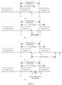
- the first timer expires before a PDU set included in a next frame enters the buffer at the RLC/PDCP layer of the terminal device (for example, at a moment t3 shown in (a) in FIG. 4 ).
- the network device determines that the PDU set #0 is not successfully uploaded, the network device does not need to explicitly notify the terminal device that the PDU set #0 is not successfully received, and the terminal device can determine, based on the timeout status of the timer of the terminal device (for example, the first timer expires, or the timing duration of the first timer is less than the frame arrival periodicity), that the PDU set #0 is not successfully received. Therefore, it is determined that the PDU set #1 does not need to be uploaded, and the PDU set #1 is discarded to save local buffer space.
- the terminal device determines, based on a timeout status of a local second timer, whether the second PDU set is successfully uploaded.
- the second timer is a timer started when the terminal device sends the first indication information
- a start moment of the second timer is a moment at which the terminal device sends the first indication information (in other words, a moment at which the terminal device completes sending the first indication information).
- an end moment of the second timer is before a second frame arrives at the buffer of the terminal device, where the second frame is a next frame of a first frame, and the first frame includes the first PDU set.
- a PDU set to be sent by the terminal device is a PDU set #1
- the PDU set #1 is a PDU set included in a frame #1.
- the PDU set #1 enters a buffer (buffer) at the RLC layer of the terminal device at a moment t1, and the terminal device starts the first timer (for example, starts a discard timer (discardTimer)) at the moment t1.
- the first timer indicates to discard the PDU set #1 if DCI for scheduling the PDU set #1 is not received before the first timer expires.
- the terminal device before submitting the PDU set #1 to the MAC layer for packet assembly, the terminal device triggers reporting of a dependency MAC CE (for example, reporting of the first indication information at a moment t2 after the moment t1), and starts the second timer (for example, a dropping packet timer (droppingPacketTimer)) at a moment at which the dependency MAC CE is reported.
- the dependency MAC CE indicates a PDU set #0 on which the PDU set #1 depends, the PDU set #0 is a reported PDU set, and the PDU set #0 is a PDU set included in a frame #0.
- the terminal device If the terminal device receives, during running of the droppingPacketTimer, DCI that is for scheduling uplink data and that is sent by the network device, the terminal device stops the running of the droppingPacketTimer. For example, the network device determines that the PDU set #0 is successfully uploaded, and may schedule the PDU set #1 by using the DCI. The terminal device determines that the PDU set #0 is successfully uploaded and terminates the droppingPacketTimer.
- the terminal device If the terminal device receives, during running of the droppingPacketTimer, DCI that is sent by the network device and that is for scheduling retransmission of the dependency MAC CE, the terminal device restarts the droppingPacketTimer after performing retransmission of the dependency MAC CE. For example, if the network device does not successfully receive the dependency MAC CE, the network device may indicate the terminal device to perform retransmission of the dependency MAC CE. Processing of the retransmission of the dependency MAC CE is similar to that of the initial transmission of the dependency MAC CE, and details are not described again.
- the timing duration of the first timer is greater than the frame arrival periodicity.
- the first timer expires after a PDU set included in a next frame enters the buffer at the RLC/PDCP layer of the terminal device (for example, at a moment t3 shown in (b) in FIG. 4 ).
- an end moment of the second timer is after the second frame arrives at the buffer of the terminal device, and a new PDU set (for example, a PDU set in a frame #2) arrives at the buffer during running of the second timer, the terminal device does not send a scheduling request (scheduling request, SR) for the new PDU set and the first indication information (for example, a dependency MAC CE for the new PDU set).
- SR scheduling request
- the first indication information for example, a dependency MAC CE for the new PDU set.
- an SR of a new PDU set and the first indication information are sent.
- the terminal device determines, based on a feedback status of the network device for the first indication information, whether the second PDU set is successfully uploaded.
- the feedback status of the network device for the first indication information may be whether the network device delivers second indication information for the first indication information, to indicate that the second PDU set is not successfully uploaded.
- that the terminal device determines, based on a feedback status of the network device for the first indication information, whether the second PDU set is successfully uploaded includes: The terminal device receives the second indication information from the network device, where the second indication information indicates that the second PDU set is not successfully uploaded.
- that the second indication information indicates that the second PDU set is not successfully uploaded includes: The second indication information indicates that a part of PDUs included in the second PDU set are not successfully uploaded or no PDUs included in the second PDU set are successfully uploaded; or the second indication information indicates that a quantity of successfully uploaded PDUs in the second PDU set is less than a first threshold.
- the timing duration of the first timer is greater than the frame arrival periodicity, to avoid a case in which UE discards a PDU set #1 in a frame #1 after a discardTimer of the frame #1 expires, when a PDU set in a frame #2 is scheduled, the PDU set #1 in the frame #1 is inevitably scheduled first, causing a waste of resources.
- the frame #2 does not depend on the frame #1.
- the network device may schedule the PDU set included in the frame #2.
- the network device schedules the PDU set included in the frame #2, if a buffer of the UE still buffers the PDU set #1 in the frame #1, the terminal device sends the PDU set #1 through transmission of an uplink resource of the PDU set included in the frame #2, causing a waste of resources. Therefore, in this implementation, the network device needs to deliver the second indication information, to indicate the terminal device to discard the PDU set #1 in the frame #1.
- the network device if the network device detects that some of depended-on PDU sets reported by the dependency MAC CE are successfully uploaded and the other some PDU sets are not successfully uploaded, the network device delivers second indication information to indicate, to the terminal device, identifiers of PDU sets that are not successfully uploaded, where the PDU sets that are not successfully uploaded include the PDU set #0.
- the terminal device determines, based on the feedback status of the network device for the first indication information, that the second PDU set is not successfully uploaded is described in detail with reference to (d) in FIG. 4 .
- a PDU set to be sent by the terminal device is a PDU set #1
- the PDU set #1 is a PDU set included in a frame #1.
- the PDU set #1 enters a buffer (buffer) at the PDCP layer of the terminal device at a moment t1, and the terminal device starts the first timer (for example, starts a discard timer (discardTimer)) at the moment t1.
- the first timer indicates to discard the PDU set #1 if DCI for scheduling the PDU set #1 is not received before the first timer expires.
- the terminal device before submitting the PDU set #1 to the MAC layer for packet assembly, triggers reporting of a dependency MAC CE (for example, reporting of the first indication information at a moment t2 after the moment t1), and the dependency MAC CE indicates a PDU set #0 on which the PDU set #1 depends.
- the PDU set #0 is a reported PDU set
- the PDU set #0 is a PDU set included in a frame #0.
- the network device determines that the PDU set #0 is not successfully uploaded (for example, the PDU set in the frame #0 is not successfully uploaded), the network device determines not to schedule the PDU set #1 in the buffer of the terminal device, and the network device determines that the timing duration of the first timer is greater than the frame arrival periodicity.
- the network device determines that the timing duration of the first timer is greater than the frame arrival periodicity.
- the network device determines not to schedule the PDU set #1, and notifies, by using the second indication information, the terminal device to discard the PDU set #1 in the buffer (for example, the second indication information is sent at a moment t5 shown in (d) in FIG. 4 ).
- the terminal device before submitting the PDU set #1 to the MAC layer for packet assembly, triggers reporting of a dependency MAC CE (for example, reporting of the first indication information at a moment t2 after the moment t1), and the dependency MAC CE indicates a PDU set #0 and a PDU set #0_1 on which the PDU set #1 depends.
- the PDU set #0 and the PDU set #0_1 are reported PDU sets, and the PDU set #0 and the PDU set #0_1 are PDU sets included in a frame #0.
- the network device determines that the PDU set #0 is not successfully uploaded (for example, the PDU set in the frame #0 is not successfully uploaded) and the PDU set #0_1 is successfully uploaded, and the network device notifies, by using the second indication information (for example, the second indication information is sent at a moment t5 shown in (d) in FIG. 4 ), the terminal device that the PDU set #0 is not successfully uploaded.
- the terminal device determines that the PDU set #0 is not successfully uploaded, and determines that the PDU set #1 depends on the PDU set #0. In this case, the PDU set #1 is deleted from the buffer.
- the example shown in (d) in FIG. 4 is similar to the example shown in (a) in FIG. 4 .
- a difference lies in that the frame #2 does not depend on the frame #1, and the network device may schedule the PDU set in the frame #2. If the UE discards the PDU set #1 in the frame #1 after the discardTimer of the frame #1 expires, the UE first schedules the PDU set in the frame #1 when scheduling the PDU set in the frame #2, causing a waste of resources. Therefore, the network device needs to additionally deliver the second indication information in the example shown in (d) in FIG. 4 , to indicate the UE to discard the PDU set #1 in the frame #1.
- the second indication information may be a MAC CE, a PDCP report, or an SDAP report, and a format and a protocol layer of the second indication information are not limited.
- the uplink data is the PDU set is used for description.
- This embodiment of this application is also applicable to other uplink data having a dependency relationship.
- the terminal device may alternatively notify, by using the first indication information, the network device that the first uplink data depends on the second uplink data.
- the terminal device does not need to schedule the first uplink data.
- the first PDU set may be replaced with a general description "first uplink data”
- the second PDU set may be replaced with a general description "second uplink data”
- the dependency relationship between the uplink data may be understood as a strong correlation between the first uplink data and the second uplink data. If the second uplink data is not successfully uploaded, it is meaningless even if the first uplink data is successfully uploaded.
- the terminal device reports the indication information indicating the second PDU set that has been sent and that is referenced by the to-be-sent first PDU set, and after sending the first indication information, determines, based on the at least one of the timeout status (for example, the timing duration or whether the started timer expires) of the started timer and the feedback status (for example, delivering the information in response to the first indication information) of the network device for the received first indication information, whether the second PDU set is successfully uploaded.
- the terminal device may learn whether the second PDU set is successfully uploaded.
- the terminal device can determine, based on a result indicating whether the second PDU set is successfully uploaded, processing on the first PDU set. For example, the second PDU set is not successfully uploaded, and the terminal device determines that the first PDU set does not need to be uploaded. Because the successful decoding of the first PDU set is premised on the successful decoding of the second PDU set, when the second PDU set is not successfully uploaded, the first PDU set cannot be correctly decoded even if the first PDU set is uploaded, and the terminal device may discard the first PDU set.
- This application further provides a communication method.
- a network device delivers fourth indication information to indicate whether a PDU is successfully received, so that a terminal device determines whether uplink data is successfully uploaded.
- the network device sends fourth indication information to a terminal device, in other words, the terminal device receives the fourth indication information from the network device.
- the fourth indication information indicates a PDU that is successfully received by the network device and/or a PDU that is not successfully received by the network device.
- That the network device determines whether a third PDU set is successfully received includes: The network device determines whether all PDUs included in the third PDU set are successfully received, and/or whether PDU data of the third PDU set that is successfully received by the network device exceeds a first threshold, where the first threshold is predefined.
- the fourth indication information may be referred to as a PDCP status report.
- the PDCP status report is submitted to an RLC layer and/or a MAC layer of the network device for transmission to the terminal device.
- the network device when the first condition is that the fourth indication information is the periodically sent information and the moment of sending the fourth indication information arrives, the network device periodically sends the fourth indication information.
- the network device detects an uplink PDU, records a successfully received PDU and an unsuccessfully received PDU, and periodically notifies, by using the fourth indication information, the terminal device of the successfully received PDU and/or the unsuccessfully received PDU.
- a periodicity of periodically sending the fourth indication information is preset (for example, the fourth indication information is delivered every 10 minutes, and a start moment of the periodic sending may be a moment at which a 1 st PDU is received).
- the network device when the first condition is that the network device receives the trigger information from the terminal device, the network device receives the trigger information from the terminal device, where the trigger information indicates the network device to deliver fourth indication information indicating a successfully received PDU and/or an unsuccessfully received PDU.
- the network device receives the trigger information of the terminal device, determines the successfully received PDU and the unsuccessfully received PDU before the trigger information is received, and notifies, by using the fourth indication information, the terminal device of the successfully received PDU and/or the unsuccessfully received PDU.
- the fifth indication information may be referred to as integrity indication information.
- the network device determines, based on the fifth indication information, whether the third PDU set is successfully received. For example, the network device determines, based on the fifth indication information, whether all PDUs included in the third PDU set are successfully received. Alternatively, for another example, the network device determines, based on the fifth indication information, whether a quantity of successfully received PDUs in the third PDU set exceeds a first threshold.
- the fifth indication information includes at least one of the following: identifiers of a 1 st PDU and a last PDU included in the third PDU set, a total quantity of PDUs included in the third PDU set, a quantity of successfully communicated PDUs needed for successful decoding of the third PDU set, a ratio of a quantity of successfully communicated PDUs needed for successful decoding of the third PDU set to a total quantity of PDUs included in the third PDU set, an identifier indicating that a PDU included in the third PDU set belongs to the third PDU set, or a sequence number of a PDU included in the third PDU set in the third PDU set.
- the terminal device may include the fifth indication information for integrity detection in the third PDU set.
- the terminal device may include the fifth indication information for integrity detection in the third PDU set.
- the terminal device learns of an identifier of the detected third PDU set and an identifier of the PDU set referenced by the third PDU set.
- the terminal device can determine, based on the identifier of the third PDU set and the identifier of the PDU set referenced by the third PDU set, the PDU set referenced by the third PDU set, and forward the identifier of the third PDU set and the identifier of the PDU set referenced by the third PDU set to a header of a data packet at a protocol layer related to the third PDU set.
- the network device does not need to learn of the PDU set referenced by the third PDU set.
- the third PDU set sent by the terminal device carries information for integrity detection, and may not carry information indicating the PDU set referenced by the third PDU set.
- the network device After receiving the third PDU set uploaded by the terminal device, the network device performs integrity detection on the third PDU set.
- the integrity detection For a specific procedure of the integrity detection, refer to the procedure in which the network device performs integrity detection on the second PDU set in the embodiment shown in FIG. 3 . Details are not described herein again.
- the terminal device can determine, based on the fourth indication information, a data packet that has been successfully communicated and a data packet that fails to be communicated, and can discard a first PDU based on a dependency relationship between a PDU set to which a PDU that fails to be communicated belongs and another PDU set.
- a method procedure shown in FIG. 5 further includes the following step: S530: The terminal device discards the first PDU.
- the fourth PDU set is a PDU set that references the third PDU set
- the fifth PDU set is a PDU set that references the third PDU set and/or the fourth PDU set
- that the fourth PDU set references the third PDU set indicates that successful decoding of the fourth PDU set is premised on successful decoding of the third PDU set
- that the fifth PDU set references the third PDU set and/or the fourth PDU set indicates that successful decoding of the fifth PDU set is premised on the successful decoding of the third PDU set and/or the fourth PDU set.
- sequence numbers of the foregoing processes do not mean execution sequences.
- the execution sequences of the processes should be determined based on functions and internal logic of the processes, and should not be construed as any limitation on the implementation processes in embodiments of this application.
- the foregoing units may independently exist, or may be completely or partially integrated.
- FIG. 7 is a diagram of a structure of a terminal device according to this application.
- the terminal device 700 may be applied to the system shown in FIG. 1 .
- FIG. 7 shows only main components of the terminal device.
- the terminal device 700 includes a processor, a memory, a control circuit, an antenna, and an input/output apparatus.
- the processor is configured to control the antenna and the input/output apparatus to send or receive a signal.
- the memory is configured to store a computer program.
- the processor is configured to invoke the computer program from the memory and run the computer program, to perform a corresponding procedure and/or operation performed by the terminal device in the communication method provided in this application. Details are not described herein.
- the processing unit 830 is configured to: when determining that the second PDU set is not successfully received, determine, for a network device, not to schedule the first PDU set.
- the receiving unit 810 and the processing unit 830 are configured to determine fourth indication information, where the fourth indication information indicates a PDU that is successfully received by the network device and/or a PDU that is not successfully received by the network device.
- the sending unit 820 is configured to send, for the apparatus 800, the fourth indication information to the terminal device when a first condition is satisfied.
- the apparatus 800 corresponds to the network device in the method embodiments.
- the apparatus 800 may be the network device in the method embodiments, or a chip or a functional module inside the network device in the method embodiments.
- Corresponding units of the apparatus 800 are configured to perform corresponding steps performed by the network device in the method embodiments shown in FIG. 3 and FIG. 5 .
- the processing unit 830 in the apparatus 800 is configured to perform corresponding steps related to processing in the network device in the method embodiments, for example, perform steps S312 and S320 in FIG. 3 , or perform step S510 in FIG. 5 .
- the sending unit 820 in the apparatus 800 is configured to perform a sending-related step of the network device, for example, step S520 in FIG. 5 .
- the receiving unit 810 in the apparatus 800 is configured to perform receiving steps of the network device in the method embodiments, for example, perform steps S311 and S310 in FIG. 3 .
- the apparatus 800 may further include a storage unit, configured to store data and/or signaling.
- the processing unit 830, the sending unit 820, and the receiving unit 810 may interact with or be coupled to the storage unit, for example, read or invoke the data and/or signaling in the storage unit, so that the method in the foregoing embodiments is performed.
- the foregoing units may independently exist, or may be completely or partially integrated.
- the network device 900 may include a central unit (central unit, CU), a distributed unit (distributed unit, DU), and an active antenna unit (active antenna unit, AAU).
- a central unit central unit, CU
- distributed unit distributed unit
- active antenna unit active antenna unit
- AAU active antenna unit
- RRU remote radio unit
- BBUs baseband units
- a non-real-time part of the original BBU is split and redefined as the CU, which is responsible for processing a non-real-time protocol and service.
- Some physical layer processing functions of the BBU are combined with the original RRU and a passive antenna into the AAU.
- the remaining functions of the BBU are redefined as the DU, which is responsible for processing a physical layer protocol and a real-time service.
- the CU and the DU are distinguished based on real-time performance of processed content, and the AAU is a combination of the RRU and the antenna.
- the CU, DU, and AAU may be separated or integrated. Therefore, there are a plurality of network deployment forms.
- a possible deployment form is consistent with that of a conventional 4G access network device, and the CU and the DU are deployed on same hardware.
- FIG. 9 is merely an example, and does not limit the protection scope of this application.
- the deployment form may alternatively be that the DU is deployed in a 5G BBU equipment room, the CU is deployed in a centralized manner or the DU is deployed in a centralized manner, the CU is centralized at a higher level, or the like.
- the AAU 901 may implement a transceiver function, and is referred to as a transceiver unit.
- the transceiver unit may also be referred to as a transceiver machine, a transceiver circuit, a transceiver, or the like, and may include at least one antenna 909 and a radio frequency unit 9010.
- the transceiver unit may include a receiving unit and a sending unit.
- the receiving unit may correspond to a receiver (which may also be referred to as a receiver machine or a receiver circuit), and the sending unit may correspond to a transmitter (which may also be referred to as a transmitter machine or a transmitter circuit).
- the CU and the DU 902 may implement an internal processing function, and are referred to as a processing unit.
- the processing unit may control the access network device or the like, and may be referred to as a controller.
- the AAU 901, the CU, and the DU 902 may be physically disposed together, or may be physically disposed separately.
- the access network device is not limited to the form shown in FIG. 9 , and may alternatively be in another form.
- the access network device includes a BBU and an ARU, or includes a BBU and an AAU, or may be CPE, or may be in another form. This is not limited in this application.
- This application further provides a computer-readable storage medium.
- the computer-readable storage medium stores instructions, and when the instructions are run on a computer, the computer is enabled to perform the steps performed by the terminal device or the network device in the methods shown in FIG. 3 and FIG. 5 .
- the disclosed system, apparatus, and method may be implemented in other manners.
- the described apparatus embodiment is merely an example.
- division into the units is merely logical function division and may be another division in actual implementation.
- a plurality of units or components may be combined or integrated into another system, or some features may be ignored or not performed.
- the displayed or discussed mutual couplings or direct couplings or communication connections may be implemented by using some interfaces.
- the indirect couplings or communication connections between the apparatuses or units may be implemented in electronic, mechanical, or other forms.
- the technical solutions of this application essentially, or the part contributing to a conventional technology, or some of the technical solutions may be implemented in a form of a software product.
- the computer software product is stored in a storage medium, and includes several instructions for instructing a computer device (which may be a personal computer, a server, a network device, or the like) to perform all or some of the steps of the methods described in embodiments of this application.
- the foregoing storage medium includes any medium that can store program code, such as a USB flash drive, a removable hard disk, a read-only memory (read-only memory, ROM), a random access memory (random access memory, RAM), a magnetic disk, or an optical disc.
- a and/or B indicate the following cases: Only A exists, both A and B exist, and only B exists.
- the character / in this specification represents or. In this application, at least one represents one and at least two (including two).
Landscapes
- Engineering & Computer Science (AREA)
- Computer Networks & Wireless Communication (AREA)
- Signal Processing (AREA)
- Mobile Radio Communication Systems (AREA)
Applications Claiming Priority (3)
| Application Number | Priority Date | Filing Date | Title |
|---|---|---|---|
| CN202210745443 | 2022-06-27 | ||
| CN202210872898.6A CN117375775A (zh) | 2022-06-27 | 2022-07-21 | 通信方法、终端设备、网络设备及通信系统 |
| PCT/CN2023/100756 WO2024001831A1 (zh) | 2022-06-27 | 2023-06-16 | 通信方法、终端设备、网络设备及通信系统 |
Publications (2)
| Publication Number | Publication Date |
|---|---|
| EP4539373A1 true EP4539373A1 (de) | 2025-04-16 |
| EP4539373A4 EP4539373A4 (de) | 2025-10-15 |
Family
ID=89383207
Family Applications (1)
| Application Number | Title | Priority Date | Filing Date |
|---|---|---|---|
| EP23830011.5A Pending EP4539373A4 (de) | 2022-06-27 | 2023-06-16 | Kommunikationsverfahren, endgerätevorrichtung, netzwerkvorrichtung und kommunikationssystem |
Country Status (2)
| Country | Link |
|---|---|
| EP (1) | EP4539373A4 (de) |
| WO (1) | WO2024001831A1 (de) |
Families Citing this family (1)
| Publication number | Priority date | Publication date | Assignee | Title |
|---|---|---|---|---|
| US20250380186A1 (en) * | 2024-06-07 | 2025-12-11 | Interdigital Patent Holdings, Inc. | Methods, architectures, apparatuses and systems for evaluation of successful transmissions |
Family Cites Families (4)
| Publication number | Priority date | Publication date | Assignee | Title |
|---|---|---|---|---|
| WO2018071050A1 (en) * | 2016-10-14 | 2018-04-19 | Intel Corporation | RETRANSMISSION PROCEDURES FOR FIFTH GENERATION (5G) NEW RADIO (NR) THINGS SIDELINK (tSL) COMMUNICATION |
| US11432188B2 (en) * | 2018-05-18 | 2022-08-30 | Qualcomm Incorporated | Indicating medium access control (MAC)-control element (CE) information |
| WO2020172762A1 (en) * | 2019-02-25 | 2020-09-03 | Huawei Technologies Co., Ltd. | Pscell activation with early data-forwarding for dual connectivity based handover |
| EP4186191A4 (de) * | 2020-07-24 | 2024-10-09 | Qualcomm Incorporated | Ratenlose codierung auf schicht 2 protokollschicht |
-
2023
- 2023-06-16 EP EP23830011.5A patent/EP4539373A4/de active Pending
- 2023-06-16 WO PCT/CN2023/100756 patent/WO2024001831A1/zh not_active Ceased
Also Published As
| Publication number | Publication date |
|---|---|
| EP4539373A4 (de) | 2025-10-15 |
| WO2024001831A1 (zh) | 2024-01-04 |
Similar Documents
| Publication | Publication Date | Title |
|---|---|---|
| US20250380184A1 (en) | Communication Method and Apparatus | |
| US20240314637A1 (en) | Data transmission method and communication apparatus | |
| CN104247543B (zh) | 数据块传输的处理时间相关控制 | |
| EP4175356A1 (de) | Drahtloskommunikationsverfahren, endgerätevorrichtung und netzwerkvorrichtung | |
| CN110089060B (zh) | 无线装置及其中的方法、网络节点及其中的方法以及介质 | |
| US20250056319A1 (en) | Communication method and apparatus | |
| CN116671222A (zh) | 用于接收数据的方法与装置和用于发送数据的方法与装置 | |
| US20230115181A1 (en) | Data transmission method and apparatus | |
| WO2023216986A1 (zh) | 缓存状态报告bsr指示方法和装置 | |
| CN117119599A (zh) | 缓存状态报告bsr指示方法和装置 | |
| EP4539373A1 (de) | Kommunikationsverfahren, endgerätevorrichtung, netzwerkvorrichtung und kommunikationssystem | |
| US20250227244A1 (en) | Communication method and apparatus | |
| CN110999455B (zh) | 一种通信方法及相关设备 | |
| CN116325953A (zh) | 配置方法和装置 | |
| CN113383591A (zh) | 一种通信方法及装置 | |
| EP4583616A1 (de) | Kommunikationsverfahren, netzwerkvorrichtung und endgerätevorrichtung | |
| CN117375775A (zh) | 通信方法、终端设备、网络设备及通信系统 | |
| EP3864903B1 (de) | Vorrichtung, verfahren und computerprogramm | |
| WO2025194621A1 (en) | Method, apparatus and system for data transmission | |
| US20240163045A1 (en) | Wireless communication method, terminal device, and network device | |
| WO2025211346A1 (en) | Reader device, communication device, and method | |
| US20240381177A1 (en) | Wireless communication method and apparatus | |
| US20250055605A1 (en) | Communication control method | |
| WO2025140298A1 (zh) | 运用于双连接dc场景下的通信方法和通信装置 | |
| WO2023108413A1 (en) | Method and apparatus of reporting buffer status |
Legal Events
| Date | Code | Title | Description |
|---|---|---|---|
| STAA | Information on the status of an ep patent application or granted ep patent |
Free format text: STATUS: THE INTERNATIONAL PUBLICATION HAS BEEN MADE |
|
| PUAI | Public reference made under article 153(3) epc to a published international application that has entered the european phase |
Free format text: ORIGINAL CODE: 0009012 |
|
| STAA | Information on the status of an ep patent application or granted ep patent |
Free format text: STATUS: REQUEST FOR EXAMINATION WAS MADE |
|
| 17P | Request for examination filed |
Effective date: 20250107 |
|
| AK | Designated contracting states |
Kind code of ref document: A1 Designated state(s): AL AT BE BG CH CY CZ DE DK EE ES FI FR GB GR HR HU IE IS IT LI LT LU LV MC ME MK MT NL NO PL PT RO RS SE SI SK SM TR |
|
| REG | Reference to a national code |
Ref country code: DE Ref legal event code: R079 Free format text: PREVIOUS MAIN CLASS: H04L0001186700 Ipc: H04L0001182900 |
|
| DAV | Request for validation of the european patent (deleted) | ||
| DAX | Request for extension of the european patent (deleted) | ||
| A4 | Supplementary search report drawn up and despatched |
Effective date: 20250916 |
|
| RIC1 | Information provided on ipc code assigned before grant |
Ipc: H04L 1/1829 20230101AFI20250910BHEP Ipc: H04L 1/1607 20230101ALI20250910BHEP |