EP4539467A2 - Kodierungsverfahren und zugehörige vorrichtung, und dekodierungsverfahren und zugehörige vorrichtung - Google Patents
Kodierungsverfahren und zugehörige vorrichtung, und dekodierungsverfahren und zugehörige vorrichtung Download PDFInfo
- Publication number
- EP4539467A2 EP4539467A2 EP25160638.0A EP25160638A EP4539467A2 EP 4539467 A2 EP4539467 A2 EP 4539467A2 EP 25160638 A EP25160638 A EP 25160638A EP 4539467 A2 EP4539467 A2 EP 4539467A2
- Authority
- EP
- European Patent Office
- Prior art keywords
- motion vector
- coding unit
- information
- umve
- current block
- Prior art date
- Legal status (The legal status is an assumption and is not a legal conclusion. Google has not performed a legal analysis and makes no representation as to the accuracy of the status listed.)
- Pending
Links
Images











Classifications
-
- H—ELECTRICITY
- H04—ELECTRIC COMMUNICATION TECHNIQUE
- H04N—PICTORIAL COMMUNICATION, e.g. TELEVISION
- H04N19/00—Methods or arrangements for coding, decoding, compressing or decompressing digital video signals
- H04N19/50—Methods or arrangements for coding, decoding, compressing or decompressing digital video signals using predictive coding
- H04N19/503—Methods or arrangements for coding, decoding, compressing or decompressing digital video signals using predictive coding involving temporal prediction
- H04N19/51—Motion estimation or motion compensation
- H04N19/573—Motion compensation with multiple frame prediction using two or more reference frames in a given prediction direction
-
- H—ELECTRICITY
- H04—ELECTRIC COMMUNICATION TECHNIQUE
- H04N—PICTORIAL COMMUNICATION, e.g. TELEVISION
- H04N19/00—Methods or arrangements for coding, decoding, compressing or decompressing digital video signals
- H04N19/50—Methods or arrangements for coding, decoding, compressing or decompressing digital video signals using predictive coding
- H04N19/503—Methods or arrangements for coding, decoding, compressing or decompressing digital video signals using predictive coding involving temporal prediction
- H04N19/51—Motion estimation or motion compensation
- H04N19/513—Processing of motion vectors
- H04N19/517—Processing of motion vectors by encoding
- H04N19/52—Processing of motion vectors by encoding by predictive encoding
-
- H—ELECTRICITY
- H04—ELECTRIC COMMUNICATION TECHNIQUE
- H04N—PICTORIAL COMMUNICATION, e.g. TELEVISION
- H04N19/00—Methods or arrangements for coding, decoding, compressing or decompressing digital video signals
- H04N19/50—Methods or arrangements for coding, decoding, compressing or decompressing digital video signals using predictive coding
- H04N19/503—Methods or arrangements for coding, decoding, compressing or decompressing digital video signals using predictive coding involving temporal prediction
- H04N19/51—Motion estimation or motion compensation
- H04N19/513—Processing of motion vectors
-
- H—ELECTRICITY
- H04—ELECTRIC COMMUNICATION TECHNIQUE
- H04N—PICTORIAL COMMUNICATION, e.g. TELEVISION
- H04N19/00—Methods or arrangements for coding, decoding, compressing or decompressing digital video signals
- H04N19/10—Methods or arrangements for coding, decoding, compressing or decompressing digital video signals using adaptive coding
- H04N19/102—Methods or arrangements for coding, decoding, compressing or decompressing digital video signals using adaptive coding characterised by the element, parameter or selection affected or controlled by the adaptive coding
- H04N19/103—Selection of coding mode or of prediction mode
-
- H—ELECTRICITY
- H04—ELECTRIC COMMUNICATION TECHNIQUE
- H04N—PICTORIAL COMMUNICATION, e.g. TELEVISION
- H04N19/00—Methods or arrangements for coding, decoding, compressing or decompressing digital video signals
- H04N19/10—Methods or arrangements for coding, decoding, compressing or decompressing digital video signals using adaptive coding
- H04N19/102—Methods or arrangements for coding, decoding, compressing or decompressing digital video signals using adaptive coding characterised by the element, parameter or selection affected or controlled by the adaptive coding
- H04N19/103—Selection of coding mode or of prediction mode
- H04N19/105—Selection of the reference unit for prediction within a chosen coding or prediction mode, e.g. adaptive choice of position and number of pixels used for prediction
-
- H—ELECTRICITY
- H04—ELECTRIC COMMUNICATION TECHNIQUE
- H04N—PICTORIAL COMMUNICATION, e.g. TELEVISION
- H04N19/00—Methods or arrangements for coding, decoding, compressing or decompressing digital video signals
- H04N19/10—Methods or arrangements for coding, decoding, compressing or decompressing digital video signals using adaptive coding
- H04N19/102—Methods or arrangements for coding, decoding, compressing or decompressing digital video signals using adaptive coding characterised by the element, parameter or selection affected or controlled by the adaptive coding
- H04N19/103—Selection of coding mode or of prediction mode
- H04N19/109—Selection of coding mode or of prediction mode among a plurality of temporal predictive coding modes
-
- H—ELECTRICITY
- H04—ELECTRIC COMMUNICATION TECHNIQUE
- H04N—PICTORIAL COMMUNICATION, e.g. TELEVISION
- H04N19/00—Methods or arrangements for coding, decoding, compressing or decompressing digital video signals
- H04N19/10—Methods or arrangements for coding, decoding, compressing or decompressing digital video signals using adaptive coding
- H04N19/134—Methods or arrangements for coding, decoding, compressing or decompressing digital video signals using adaptive coding characterised by the element, parameter or criterion affecting or controlling the adaptive coding
- H04N19/136—Incoming video signal characteristics or properties
- H04N19/137—Motion inside a coding unit, e.g. average field, frame or block difference
- H04N19/139—Analysis of motion vectors, e.g. their magnitude, direction, variance or reliability
-
- H—ELECTRICITY
- H04—ELECTRIC COMMUNICATION TECHNIQUE
- H04N—PICTORIAL COMMUNICATION, e.g. TELEVISION
- H04N19/00—Methods or arrangements for coding, decoding, compressing or decompressing digital video signals
- H04N19/10—Methods or arrangements for coding, decoding, compressing or decompressing digital video signals using adaptive coding
- H04N19/134—Methods or arrangements for coding, decoding, compressing or decompressing digital video signals using adaptive coding characterised by the element, parameter or criterion affecting or controlling the adaptive coding
- H04N19/157—Assigned coding mode, i.e. the coding mode being predefined or preselected to be further used for selection of another element or parameter
- H04N19/159—Prediction type, e.g. intra-frame, inter-frame or bidirectional frame prediction
-
- H—ELECTRICITY
- H04—ELECTRIC COMMUNICATION TECHNIQUE
- H04N—PICTORIAL COMMUNICATION, e.g. TELEVISION
- H04N19/00—Methods or arrangements for coding, decoding, compressing or decompressing digital video signals
- H04N19/10—Methods or arrangements for coding, decoding, compressing or decompressing digital video signals using adaptive coding
- H04N19/169—Methods or arrangements for coding, decoding, compressing or decompressing digital video signals using adaptive coding characterised by the coding unit, i.e. the structural portion or semantic portion of the video signal being the object or the subject of the adaptive coding
- H04N19/17—Methods or arrangements for coding, decoding, compressing or decompressing digital video signals using adaptive coding characterised by the coding unit, i.e. the structural portion or semantic portion of the video signal being the object or the subject of the adaptive coding the unit being an image region, e.g. an object
- H04N19/176—Methods or arrangements for coding, decoding, compressing or decompressing digital video signals using adaptive coding characterised by the coding unit, i.e. the structural portion or semantic portion of the video signal being the object or the subject of the adaptive coding the unit being an image region, e.g. an object the region being a block, e.g. a macroblock
-
- H—ELECTRICITY
- H04—ELECTRIC COMMUNICATION TECHNIQUE
- H04N—PICTORIAL COMMUNICATION, e.g. TELEVISION
- H04N19/00—Methods or arrangements for coding, decoding, compressing or decompressing digital video signals
- H04N19/10—Methods or arrangements for coding, decoding, compressing or decompressing digital video signals using adaptive coding
- H04N19/169—Methods or arrangements for coding, decoding, compressing or decompressing digital video signals using adaptive coding characterised by the coding unit, i.e. the structural portion or semantic portion of the video signal being the object or the subject of the adaptive coding
- H04N19/184—Methods or arrangements for coding, decoding, compressing or decompressing digital video signals using adaptive coding characterised by the coding unit, i.e. the structural portion or semantic portion of the video signal being the object or the subject of the adaptive coding the unit being bits, e.g. of the compressed video stream
-
- H—ELECTRICITY
- H04—ELECTRIC COMMUNICATION TECHNIQUE
- H04N—PICTORIAL COMMUNICATION, e.g. TELEVISION
- H04N19/00—Methods or arrangements for coding, decoding, compressing or decompressing digital video signals
- H04N19/50—Methods or arrangements for coding, decoding, compressing or decompressing digital video signals using predictive coding
- H04N19/503—Methods or arrangements for coding, decoding, compressing or decompressing digital video signals using predictive coding involving temporal prediction
- H04N19/51—Motion estimation or motion compensation
- H04N19/513—Processing of motion vectors
- H04N19/521—Processing of motion vectors for estimating the reliability of the determined motion vectors or motion vector field, e.g. for smoothing the motion vector field or for correcting motion vectors
-
- H—ELECTRICITY
- H04—ELECTRIC COMMUNICATION TECHNIQUE
- H04N—PICTORIAL COMMUNICATION, e.g. TELEVISION
- H04N19/00—Methods or arrangements for coding, decoding, compressing or decompressing digital video signals
- H04N19/70—Methods or arrangements for coding, decoding, compressing or decompressing digital video signals characterised by syntax aspects related to video coding, e.g. related to compression standards
Definitions
- the present disclosure relates to a video encoding method and a video decoding method, and more particularly, to a method of efficiently encoding and decoding information about a motion vector.
- a prediction method is determined in consideration of a size of residual data and encoding information.
- data units split from a picture have various sizes, and as a size of a data unit increases, the likelihood of the accuracy of prediction decreasing increases whereas encoding information decreases. Accordingly, a size of a block is determined in accordance with characteristics of the picture.
- prediction methods include intra prediction and inter prediction.
- Intra prediction is a method of predicting pixels of a block from neighboring pixels around the block.
- Inter prediction is a method of predicting pixels by referring to pixels of another picture referenced by a picture including the block. Accordingly, spatial redundancy is removed in intra prediction, and temporal redundancy is removed in inter prediction.
- a " ⁇ unit” may include, by way of example, components such as software components, object-oriented software components, class components, and task components, processes, functions, attributes, procedures, subroutines, segments of program code, drivers, firmware, microcode, circuitry, data, databases, data structures, tables, arrays, and variables.
- components such as software components, object-oriented software components, class components, and task components, processes, functions, attributes, procedures, subroutines, segments of program code, drivers, firmware, microcode, circuitry, data, databases, data structures, tables, arrays, and variables.
- current block refers to one of a coding unit, a prediction unit, and a transform unit which are currently encoded or decoded.
- a "current coding unit”, a “current prediction unit”, and a “current transform unit” may be used when other types of blocks such as a prediction unit and a transform unit need to be distinguished from one another.
- the term “lower block” refers to a data unit split from the "current block”.
- the term “upper block” refers to a data unit including the "current block”.
- a coding unit having a certain size may be split by using a specific splitting method. For example, when a size of a coding unit is 256x265, the coding unit may be set to be split into only four square units whose width and height are half those of the coding unit.
- a finally split coding unit may be predicted by using intra prediction or inter prediction.
- Intra prediction is a method of predicting samples of a prediction unit by using reference samples around the prediction unit.
- Inter prediction is a method of predicting samples of a prediction unit by obtaining reference samples from a reference picture referenced by a current picture.
- the split information extracted by the decoder 170 is split information of a tree structure determined by the image encoding device 100 to generate a minimum coding error. Therefore, the image decoding device 150 may reconstruct an image by decoding data according to a decoding method that generates the minimum coding error.
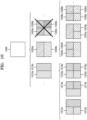
- the image decoding device 150 may determine to split or not to split a square first coding unit 400 into coding units based on at least one of the block shape information and the split shape information. According to an embodiment, when the split shape information indicates to split the first coding unit 400 in a horizontal direction, the image decoding device 150 may determine a second coding unit 410 by splitting the first coding unit 400 in a horizontal direction.
- a first coding unit, a second coding unit, and a third coding unit used according to an embodiment are terms used to understand a relation before and after splitting a coding unit. For example, the second coding unit may be determined by splitting the first coding unit, and the third coding unit may be determined by splitting the second coding unit. It will be understood that a relationship among the first coding unit, the second coding unit, and the third coding unit applies to the following descriptions.
- the restrictions on the third coding unit 420c at the center location are not limited to the above-described examples, and may include various restrictions for decoding the third coding unit 420c at the center location differently from the other third coding units 420b and 420d.
- the image decoding device 150 may determine the coding unit 520b of the center location by determining the locations of the coding units 520a, 520b, and 520c based on information indicating locations of certain samples included in the coding units 520a, 520b, and 520c.
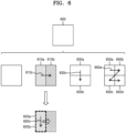
- the image decoding device 150 may determine the coding unit 520b at the center location by determining the locations of the coding units 520a, 520b, and 520c based on information indicating locations of top left samples 530a, 530b, and 530c of the coding units 520a, 520b, and 520c.
- the information indicating the locations of the top left samples 530a, 530b, and 530c, which are respectively included in the coding units 520a, 520b, and 520c, respectively may include information indicating widths or heights of the coding units 520a, 520b, and 520c included in the current coding unit 500, and the widths or heights may correspond to information indicating differences between the coordinates of the coding units 520a, 520b, and 520c in the picture.
- the image decoding device 150 may determine the coding unit 520b at the center location by directly using the information about the locations or coordinates of the coding units 520a, 520b, and 520c in the picture, or by using the information about the widths or heights of the coding units, which correspond to difference values between the coordinates.
- information indicating the location of the top left sample 530a of the upper coding unit 520a may include coordinates (xa, ya)
- information indicating the location of the top left sample 530b of the middle coding unit 520b may include coordinates (xb, yb)
- information indicating the location of the top left sample 530c of the lower coding unit 520c may include coordinates (xc, yc).
- the image decoding device 150 may determine the middle coding unit 520b by using the coordinates of the top left samples 530a, 530b, and 530c which are included in the coding units 520a, 520b, and 520c, respectively.
- the coordinates indicating the locations of the top left samples 530a, 530b, and 530c may include coordinates indicating absolute locations in the picture, or may use coordinates (dxb, dyb) indicating a relative location of the top left sample 530b of the middle coding unit 520b and coordinates (dxc, dyc) indicating a relative location of the top left sample 530c of the lower coding unit 520c, with reference to the location of the top left sample 530a of the upper coding unit 520a.
- a method of determining a coding unit at a certain location by using coordinates of a sample included in the coding unit as information indicating a location of the sample is not limited to the above-described method, and may include various arithmetic methods capable of using the coordinates of the sample.
- the above-described method, performed by the image decoding device 150, of determining a coding unit having a size different from the size of the other coding units merely corresponds to an example of determining a coding unit at a certain location by using sizes of coding units, which are determined based on coordinates of samples, and thus various methods of determining a coding unit at a certain location by comparing sizes of coding units, which are determined based on coordinates of certain samples, may be used.
- locations of samples considered to determine locations of coding units are not limited to the above-described top left locations, and information about arbitrary locations of samples included in the coding units may be used.
- the image decoding device 150 may select a coding unit at a certain location from among an odd number of coding units determined by splitting a current coding unit, considering a shape of the current coding unit. For example, when the current coding unit has a non-square shape, a width of which is longer than a height, the image decoding device 150 may determine the coding unit at the certain location in a horizontal direction. That is, the image decoding device 150 may determine one of coding units at different locations in a horizontal direction and may put a restriction on the coding unit. When the current coding unit has a non-square shape, a height of which is longer than a width, the image decoding device 150 may determine the coding unit at the certain location in a vertical direction. That is, the image decoding device 150 may determine one of coding units at different locations in a vertical direction and may put a restriction on the coding unit.
- certain information about a coding unit at a certain location may be used in a splitting operation to determine the coding unit at the certain location from among the plurality of coding units.
- the image decoding device 150 may use at least one of block shape information and split shape information, which is stored in a sample included in a coding unit at a center location, in a splitting operation to determine the coding unit at the center location from among the plurality of coding units determined by splitting the current coding unit.
- the image decoding device 150 may determine one of samples adjacent to a boundary for splitting a long side of the current coding unit in half, as the sample from which the certain information may be obtained.
- a coding unit may be recursively split based on at least one of the block shape information and the split shape information, which is obtained from the sample at the certain location in each coding unit.
- the image decoding device 150 may determine to process the second coding units 650a to 650d, which are determined by splitting the first coding unit 600 in vertical and horizontal directions, in a certain order for processing coding units in a row and then processing coding units in a next row (e.g., in a raster scan order or a Z-scan order 650e).
- FIG. 7 illustrates a process, performed by the image decoding device 150, of determining that a current coding unit is to be split into an odd number of coding units when the coding units are not processable in a certain order according to an embodiment.
- the image decoding device 150 may determine whether the third coding units 720a and 720b, and 720c, 720d, and 720e included in the first coding unit 700 satisfy the condition for processing in the certain order, and the condition relates to whether at least one of a width and height of the second coding units 710a and 710b is split in half along a boundary of the third coding units 720a and 720b, and 720c, 720d, and 720e.
- the image decoding device 150 may put a certain restriction on a coding unit at a certain location among the split coding units, and the restriction or the certain location has been described above through various embodiments and thus detailed descriptions thereof will not be provided here.
- the image decoding device 150 may determine whether the second coding units 810a, 810b, 810c, 820a, 820b, and 820c included in the first coding unit 800 satisfy a condition for processing in a certain order, and the condition relates to whether at least one of a width and height of the first coding unit 800 is split in half along a boundary of the second coding units 810a, 810b, 810c, 820a, 820b, and 820c.
- the image decoding device 150 may decide disconnection of a scan order, and may determine that the first coding unit 800 is split into an odd number of coding units based on a result of the decision. According to an embodiment, when a coding unit is split into an odd number of coding units, the image decoding device 150 may put a certain restriction on a coding unit at a certain location from among the split coding units, and the restriction or the certain location has been described above through various embodiments and thus detailed descriptions thereof will not be provided here.
- the image decoding device 150 may determine square third coding units 1022a and 1022b by splitting the upper second coding unit 1020a in a vertical direction, and may determine square third coding units 1024a and 1024b by splitting the lower second coding unit 1020b in a vertical direction. Furthermore, the image decoding device 150 may determine square third coding units 1026a, 1026b, 1026c, and 1026d by splitting both the upper and lower second coding units 1020a and 1020b in a vertical direction. In this case, coding units having the same shape as the four square second coding units 1030a, 1030b, 1030c, and 1030d split from the first coding unit 1000 may be determined.
- the image decoding device 150 may split a first coding unit 1100 based on block shape information and split shape information.
- the image decoding device 150 may determine second coding units 1110a, 1110b, 1120a, 1120b, etc. by splitting the first coding unit 1100.
- the non-square second coding units 1110a, 1110b, 1120a, and 1120b determined by splitting the first coding unit 1100 in only a horizontal direction or vertical direction may be independently split based on the block shape information and the split shape information of each coding unit.
- the image decoding device 150 may determine the third coding units 1126a, 1126b, 1126c, and 1126d by splitting the second coding units 1120a and 1120b generated by splitting the first coding unit 1100 in a horizontal direction, in a vertical direction, and may process the third coding units 1126a, 1126b, 1126c, and 1126d in a processing order 1127 for initially processing the third coding units 1126a and 1126b, which are included in the upper second coding unit 1120a, in a horizontal direction and then processing the third coding unit 1126c and 1126d, which are included in the lower second coding unit 1120b, in a horizontal direction.
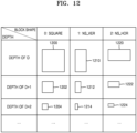
- the image decoding device 150 may determine a second coding unit 1202, a third coding unit 1204, etc. of deeper depths by splitting a square first coding unit 1200 based on block shape information indicating a square shape (e.g., the block shape information may be expressed as '0: SQUARE').
- block shape information indicating a square shape
- the second coding unit 1202 determined by splitting a width and height of the first coding unit 1200 in 1/2 ⁇ 1 may have a size of N ⁇ N.
- the third coding unit 1204 determined by splitting a width and height of the second coding unit 1202 in 1/2 may have a size of N/2 ⁇ N/2.
- a width and height of the third coding unit 1204 are 1/22 times those of the first coding unit 1200.
- a depth of the first coding unit 1200 is D
- a depth of the second coding unit 1202 the width and height of which are 1/21 times those of the first coding unit 1200, may be D+1
- a depth of the second coding units 1306a, 1306b, 1306c, and 1306d may be D+1 which is deeper than the depth D of the first coding unit 1300 by 1.
- the image decoding device 150 may determine PIDs for identifying split coding units, based on a size ratio between the coding units when an odd number of split coding units do not have equal sizes.
- the coding unit 1314b of a center location among the odd number of split coding units 1314a, 1314b, and 1314c may have a width which is equal to that of the other coding units 1314a and 1314c and a height which is two times that of the other coding units 1314a and 1314c. That is, in this case, the coding unit 1314b at the center location may include two of the other coding unit 1314a or 1314c.
- the image decoding device 150 may previously determine a minimum size allowed for the reference data units included in the current picture. Accordingly, the image decoding device 150 may determine various reference data units having sizes equal to or greater than the minimum size, and may determine one or more coding units by using the split shape information and block shape information with reference to the determined reference data units.
- the image decoding device 150 may use a square reference coding unit 1400 or a non-square reference coding unit 1402.
- the shape and size of reference coding units may be determined based on various data units capable of including one or more reference coding units (e.g., sequences, pictures, slices, slice segments, largest coding units, or the like).
- the image decoding device 150 may determine at least one of the size and shape of reference coding units included in a data unit serving as a unit for obtaining the PID, by selecting the previously determined at least one of the size and shape of reference coding units based on the PID.
- the receiver 160 of the image decoding device 150 may obtain the processing block size information from the bitstream according to each specific data unit.
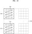
- the processing block size information may be obtained from the bitstream in a data unit such as an image, sequence, picture, slice, or slice segment. That is, the receiver 160 may obtain the processing block size information from the bitstream according to each of the various data units, the image decoding device 150 may determine the size of one or more processing blocks, which are split from the picture, by using the obtained processing block size information, and the size of the processing blocks may be integer times that of the reference coding units.
- the image decoding device 150 may determine the processing blocks 1502 and 1512, which are included in the picture 1500, based on the size of processing blocks, and may determine a determination order of one or more reference coding units included in the processing blocks 1502 and 1512. According to an embodiment, determination of reference coding units may include determination of the size of the reference coding units.
- the image decoding device 150 may obtain, from the bitstream, the determination order information of reference coding units according to each specific data unit.
- the receiver 160 may obtain the determination order information of reference coding units from the bitstream according to each data unit such as an image, sequence, picture, slice, slice segment, or processing block. Because the determination order information of reference coding units indicates an order for determining reference coding units in a processing block, the determination order information may be obtained with respect to each specific data unit including an integer number of processing blocks.
- FIGS. 1 through 15 A method of splitting an image into largest coding units and splitting a largest coding unit into coding units having a hierarchical tree structure has been described with reference to FIGS. 1 through 15 .
- An ultimate motion vector expression (UMVE) mode for deriving a motion vector for inter prediction will be described with reference to FIGS. 16 through 28 .
- a base motion vector 1600 obtained from UMVE candidates of a current block is (5, -4).
- the base motion vector 1600 may be corrected according to a correction distance 1602 and a correction direction 1604.
- FIG. 17 is a block diagram of a video decoding device 1700 for performing decoding according to a UMVE mode.
- the video decoding device 1700 includes an upper parameter determiner 1710, a coding mode determiner 1720, and a decoder 1730.
- the upper parameter determiner 1710, the coding mode determiner 1720, and the decoder 1730 are separate elements in FIG. 17 , according to an embodiment, the upper parameter determiner 1710, the coding mode determiner 1720, and the decoder 1730 may be implemented as one element.
- the upper parameter determiner 1710, the coding mode determiner 1720, and the decoder 1730 are elements located in one device in FIG. 17 , devices responsible for functions of the upper parameter determiner 1710, the coding mode determiner 1720, and the decoder 1730 do not need to be physically adjacent to one another. Accordingly, according to an embodiment, the upper parameter determiner 1710, the coding mode determiner 1720, and the decoder 1730 may be distributed.
- the upper parameter determiner 1710, the coding mode determiner 1720, and the decoder 1730 may be implemented by using one processor according to an embodiment. Also, the upper parameter determiner 1710, the coding mode determiner 1720, and the decoder 1730 may be implemented by using a plurality of processors according to an embodiment.
- the UMVE enabled flag When the UMVE enabled flag is 1, the UMVE enabled flag may be interpreted as allowing the UMVE mode for the upper data unit. In contrast, when the UMVE enabled flag is 0, the UMVE enabled flag may be interpreted as not allowing the UMVE mode for the upper data unit. According to an embodiment, the meaning of the UMVE enabled flag may be interpreted in the opposite way.
- the upper parameter determiner 1710 may obtain correction distance candidate number information indicating the number of correction distance candidates allowed for the upper data unit from the bitstream.
- the decoder 1730 determines as many correction distance candidates as the number indicated by the correction distance candidate number information.
- the UMVE candidate number information may indicate a difference between a minimum UMVE candidate number and a UMVE candidate number used in the upper data unit. For example, when the minimum UMVE candidate number is 4 and the UMVE candidate number used in the upper data unit is 5, the UMVE candidate number information may indicate 1.
- the correction distance candidate number information and the correction direction candidate number information may also indicate a difference between a minimum number and a candidate number used in the upper data unit, like the UMVE candidate number information.
- the temporal distance between the current picture and the reference picture may be determined according to one or more threshold values. For example, when the number of threshold values is 3, the minimum value of the correction distance candidates may be determined by comparing the temporal distance between the current picture and the reference picture with three threshold values.
- the upper parameter determiner 1710 may determine the minimum value of the correction distance candidates of the upper data unit according to the temporal distance between the current picture and the reference picture and a correction distance candidate minimum value of the correction distance range information. In detail, because the correction distance candidate minimum value of the correction distance range information changes according to the temporal distance between the current picture and the reference picture, the minimum value of the correction distance candidates of the upper data unit may be determined.
- the decoder 1730 may change a prediction direction of the current block. For example, when change of the prediction direction is allowed, even if the prediction direction of the UMVE candidate is list 0 uni-prediction, the prediction direction of the current block may be determined to be list 1 uni-prediction or bi-prediction.
- the upper parameter determiner 1710 may obtain main prediction direction information of the upper data unit from the bitstream.
- the main prediction direction information indicates whether there is a main prediction direction of the upper data unit. Also, when there is a main prediction direction of the upper data unit, the main prediction direction information indicates the main prediction direction of the upper data unit.
- the main prediction direction of the upper data unit is set, blocks which are included in the upper data unit and to which the UMVE mode is applied are predicted according to the main prediction direction. For example, when the main prediction direction is determined to be bi-prediction, blocks to which the UMVE mode is applied may be bi-predicted. Accordingly, even when the prediction direction of the UMVE candidate is uni-prediction, the prediction direction of the current block may be determined to be bi-prediction.
- the coding mode determiner 1720 determines whether the UMVE mode is applied to the current block.
- the coding mode determiner 1720 may obtain a UMVE flag indicating whether the UMVE mode is applied to the current block from the bitstream. For example, when the UMVE flag indicates that the UMVE mode is applied to the current block, the coding mode determiner 1720 may determine that the prediction mode of the current block is the UMVE mode. In contrast, when the UMVE flag indicates that the UMVE mode is not applied to the current block, the coding mode determiner 1720 does not determine that the prediction mode of the current block is the UMVE mode.
- the coding mode determiner 1720 may determine that another intra prediction mode is to be applied to the current block.
- the other intra prediction mode may include a DMVD mode, a DMVR mode, a merge mode, an OBMC mode, an IC mode, and an affine mode.
- the decoder 1730 may determine the base motion vector of the current block from the UMVE candidates.
- the decoder 1730 may determine the UMVE candidate list according to the UMVE candidate list construction method according to the UMVE candidate list construction information.
- the number of the UMVE candidates included in the UMVE candidate list may be determined according to the UMVE candidate number information.
- the decoder 1730 may obtain a UMVE index indicating UMVE candidates including the reference picture and the base motion vector of the current block from the UMVE candidate list from the bitstream. The decoder 1730 may determine the reference picture and the base motion vector of the current block according to the UMVE index.
- the decoder 1730 may determine the correction distance and the correction direction for correction of the base motion vector.
- the base motion vector is corrected for the accuracy of prediction in the UMVE mode. Accordingly, in order to determine a correction motion vector for correction of the base motion vector, the decoder 1730 determines a correction distance indicating a size of the correction motion vector and a correction direction indicating a direction of the correction motion vector.
- the decoder 1730 may determine correction direction candidates according to the correction direction candidate number information of the upper data unit.
- the decoder 1730 determines the correction direction from a certain number of correction direction candidates.
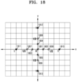
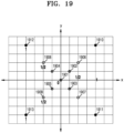
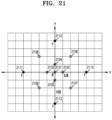
- FIGS. 18 through 21 are diagrams for describing a process of determining a motion vector of a current block in a UMVE mode.
- coordinates of a base motion vector are set to (base_x, base_y).
- a correction motion vector according to a correction distance and a correction direction of a UMVE mode is described based on (base_x, base_y).
- the decoder 1730 may determine motion vector candidates having a diamond distribution based on the base motion vector.
- the decoder 1730 may determine motion vector candidates (base_x+1/2, base_y) 1806, (base_x-1/2, base_y) 1807, (base_x, base_y+1/2) 1808, and (base_x, base_y-1/2) 1809 at a 1/2 pixel distance from the base motion vector (base_x, base_y) 1801 as a second candidate group.
- the decoder 1730 may determine motion vector candidates (base_x+1, base_y) 1810, (base_x-1, base_y) 1811, (base_x, base_y+1) 1812, and (base_x, base_y-1) 1813 at a 1 pixel distance from the base motion vector (base_x, base_y) 1801 as a third candidate group.
- the decoder 1730 may select one from among the first candidate group through the third candidate group according to a correction distance.
- the decoder 1730 may determine one motion vector candidate from among candidate groups according to the correction direction as a motion vector of a current block.
- the decoder 1730 may determine each group by using different numbers of motion vector candidates. Although an interval between pixels is a 1/4 pixel distance, for convenience, component values of vector candidates are scaled four times.
- the decoder 1730 may determine eight motion vector candidates (base_x+1/2, base_y) 2010, (base_x-1/2, base_y) 2011, (base_x, base_y+1/2) 2012, (base_x, base_y-1/2) 2013, (base_x+1/2, base_y+1/2) 2014, (base_x+1/2, base_y-1/2) 2015, (base_x-1/2, base_y+1/2) 2016, and (base_x-1/2, base_y-1/2) 2017 at a 1/2 pixel distance from the base motion vector as a second candidate group.
- correction directions of a base motion vector of list 0 and a base motion vector of list 1 are determined to be the same.
- a correction direction of the base motion vector of list 0 is determined to be opposite to a correction direction of the base motion vector of list 1.
- the correction distance and the correction direction used for correction of the base motion vector of list 0 may be changed in consideration of a distance between the current picture and the reference picture of list 0 and a distance between the current picture and the reference picture of list 1.
- the changed correction distance and the changed correction direction may be applied to the base motion vector of list 1.
- the correction distance and the correction direction indicated by the correction distance information and the correction direction information may be applied to the base motion vector of list 1, and the changed correction distance and the changed correction direction may be applied to the base motion vector of list 0.
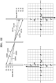
- FIG. 22 illustrates a method of correcting two base motion vectors according to bi-prediction according to an embodiment.
- a base motion vector 2202 of list 0 is (0, -1).
- a base motion vector 2212 of list 1 is (0, 2).
- the motion vector 2214 of list 1 is determined to be (0, 3) whose y component is greater by 1 from that of the base motion vector 2212 of list 1.
- a motion vector 2206 of list 0 is determined to be (0, -3), and a motion vector 2216 of list 1 is determined to be (0, 4). Also, when the correction distance of the base motion vector 2202 of list 0 is 4, a motion vector 2208 of list 0 is determined to be (0, -5) and a motion vector 2218 of list 1 is determined to be (0, 6).
- the decoder 1730 may obtain prediction direction information from a bitstream and may change a prediction direction of a current block according to the prediction direction information.
- the prediction direction information may indicate whether to change the prediction direction.
- the prediction direction information does not indicate change of the prediction direction, the current block is predicted according to a prediction direction of a UMVE candidate.
- the prediction direction information indicates change of the prediction direction, the current block is predicted according to a prediction direction different from that of the UMVE candidate.
- the prediction direction information may indicate a changed prediction direction.
- the prediction direction information may indicate one of list 1 uni-prediction and bi-prediction. Accordingly, the prediction direction information may indicate whether the prediction direction changes and the changed prediction direction.
- the prediction direction information may be set to 10 or 11.
- the prediction direction information may be set to 10.
- the prediction direction information may be set to 11.
- the prediction direction information may be set to 0.
- the decoder 1730 may change a motion vector of the UMVE candidate according to the changed prediction direction. For example, when the prediction direction of the UMVE candidate is list 0 uni-prediction and the prediction direction of the current block is list 1 uni-prediction, a motion vector of list 0 is corrected to be suitable for prediction according to the reference picture of list 1.
- the motion vector of list 0 may be modified by being scaled according to a ratio between a temporal distance between the current picture and the reference picture of list 0 and a temporal distance between the current picture and the reference picture of list 1.
- a motion vector of list 1 may be determined to be (4, 3).
- the ratio between the temporal distances is 2:-1, that is, when the reference picture of list 1 and the reference picture of list 0 are located in different directions from the current picture, the motion vector of list 1 may be determined to be (-4, -3).
- the motion vector of list 0 may be obtained from the motion vector of list 1.
- the reference picture of list 0 may be determined to be a picture located at a specific order of list 0.
- the motion vector and the reference picture of list 0 and the motion vector and the reference picture of list 1 may all be used for prediction of the current block.
- the current block is predicted by using only the motion vector and the reference picture of list 0 from among the motion vector and the reference picture of list 0 and the motion vector and the reference picture of list 1.
- the prediction direction before change is bi-prediction and the changed prediction direction is list 1 uni-prediction
- the current block is predicted by using only the motion vector and the reference picture of list 1 from among the motion vector and the reference picture of list 0 and the motion vector and the reference picture of list 1.
- the decoder 1730 may change the prediction direction of the current block according to the prediction direction information.
- the prediction direction information indicates the prediction direction of the current block from among the main prediction direction and two auxiliary prediction directions.
- the prediction direction information indicates the main prediction direction
- the current block is predicted according to the main prediction direction.
- the prediction direction information indicates an auxiliary prediction direction
- the current block is predicted according to the prediction direction indicated by the prediction direction information from among the two auxiliary prediction directions.
- the decoder 1730 may correct a corrected base motion vector once more. Accordingly, the decoder 1730 may obtain additional correction distance information and additional correction direction information from a bitstream. The decoder 1730 may correct the base motion vector once more based on an additional correction distance determined according to the additional correction distance information and an addition correction direction determined according to the additional correction direction information.
- the decoder 1730 may obtain the additional correction distance information and the additional correction direction information.
- the additional correction distance and the additional correction direction respectively indicated by the additional correction distance information and the additional correction direction information may be limited according to the correction distance and the correction direction. For example, the additional correction distance may be determined to be less than the correction distance. Alternatively, the additional correction direction may be determined to be different from the correction direction.
- the decoder 1730 may reconstruct the current block based on a motion vector and a reference picture of the current block.
- the prediction direction of the current block is list 0 uni-prediction or list 1 uni-prediction
- the decoder 1730 may predict the current block by using one motion vector and one reference picture.
- the prediction direction of the current block is bi-prediction
- the decoder 1730 may predict the current block by using the motion vector and the reference picture of list 0 and the motion vector and the reference picture of list 1.
- the decoder 1730 may reconstruct the current block according to a prediction result of the current block.
- the decoder 1730 may reconstruct the current block according to a residual block of the current block and a prediction block.
- the residual block of the current block indicates a difference value between the prediction block and a reconstruction block of the current block.
- UMVE candidate number information of UMVE candidates decoded by the video decoding device 1700 may be binarized according to fixed length coding or truncated unary coding.
- Functions of the upper parameter determiner 1710, the coding mode determiner 1720, and the decoder 1730 may be performed by the decoder 170 of FIG. 1B .
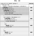
- the inter mode tool may be used in the skip mode.
- a umve mode, an affine mode, and a merge mode may be used in the skip mode.
- cu_skip_flag[ x0 ][ y0 ] indicating whether the sip mode is applied to the current block is obtained.
- cu_skip_umve[ x0 ][ y0 ] indicating whether the inter mode tool of the current block is the umve mode is obtained.
- whether a mode is applied is determined in an order of the umve mode, the affine mode, and the merge mode.
- one of ordinary skill in the art may easily change a type of the inter mode tool used in the skip mode.
- one of ordinary skill in the art may change a determination order of the inter mode tool used in the skip mode.
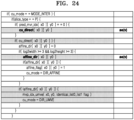
- FIG. 24 illustrates a method of selecting an inter mode tool of a current block in a direct mode, when a slice type of a current slice including the current block is P-type.
- the direct mode some pieces of encoding information required to determine a motion vector of the current block are skipped. Accordingly, because encoding information required to determine the motion vector of the current block is reduced, coding efficiency may be improved.
- whether a mode is applied is determined in an order of the affine mode and the umve mode.
- one of ordinary skill in the art may easily change a type of the inter mode tool used in the direct mode.
- one of ordinary skill in the art may change a determination order of the inter mode tool used in the direct mode.
- FIG. 25 illustrates a method of selecting an inter mode tool of a current block in a direct mode, when a slice type of a current slice including the current block is B-type.
- a umve mode, an affine mode, and a merge mode may be used.
- cu_direct[ x0 ][ y0 ] indicating whether the direct mode is applied to the current block is obtained.
- cu_direct_umve[ x0 ][ y0 ] indicating whether the inter mode tool of the current block is the umve mode is obtained.
- FIG. 26 is a flowchart of a decoding method according to a UMVE mode of the video decoding device 1700 of FIG. 17 .
- Whether a UMVE mode is allowed for an upper data unit including a current block may be determined according to a UMVE enabled flag obtained from a bitstream.
- Correction direction candidate number information indicating the number of correction direction candidates may be obtained from the bitstream.
- Prediction direction change permission information of the plurality of blocks of the upper data unit may be obtained from the bitstream.
- Main prediction direction information indicating a main prediction direction of the upper data unit may be obtained from the bitstream.
- the number of correction distance candidates of the current block indicated by the correction distance candidate number information may be determined. Correction distance candidates may be determined based on a correction distance range indicated by the correction distance range information. Also, when the correction distance change information indicates that a correction distance of a base motion vector adaptively changes according to a distance between a current picture and a reference picture of the current block, the correction distance range may change according to the distance between the current picture and the reference picture of the current block.
- a correction distance and a correction direction for correction of the base motion vector are determined.
- the correction distance of the base motion vector may be determined from among the correction distance candidates according to the correction distance information obtained from the bitstream.
- the correction direction of the base motion vector may be determined from among the correction direction candidates according to the correction direction information obtained from the bitstream.
- the current block is reconstructed based on the motion vector of the current block.
- the encoding parameter determiner 2710, the motion vector determiner 2720, the encoding information determiner 2730, and the output unit 2740 may be implemented by using one processor according to an embodiment. Also, the encoding parameter determiner 2710, the motion vector determiner 2720, the encoding information determiner 2730, and the output unit 2740 may be implemented by using a plurality of processors according to an embodiment.
- the motion vector determiner 2720 determines a motion vector of the current block.
- the motion vector determiner 2720 may obtain a plurality of motion vectors from neighboring blocks around the current block.
- the motion vector determiner 2720 may determine the motion vector of the current block by scanning surroundings of the plurality of motion vectors.
- the motion vector determiner 2720 may determine an optimal motion vector as the motion vector of the current block according to rate-distortion optimization.
- the encoding information determiner 2730 determines whether the UMVE mode is applied to the current block according to the motion vector.
- the encoding information determiner 2730 may determine whether the motion vector of the current block determined by the motion vector determiner 2720 may be derived by using the UMVE mode.
- the encoding information determiner 2730 may determine to apply the UMVE mode to the current block.
- a minimum error between the motion vector of the current block and the motion vector according to the UMVE mode is equal to or less than a threshold value, the encoding information determiner 2730 may determine to apply the UMVE mode to the current block.
- the encoding information determiner 2730 determines a base motion vector of the current block and a correction distance and a correction direction for correction of the base motion vector according to the motion vector of the current block.
- the encoding information determiner 2730 may determine the correction distance and the correction direction according to a difference between the motion vector of the current block and the base motion vector of the current block.
- FIG. 28 illustrates a flowchart of an encoding method according to a UMVE mode of the video encoding device 2700 of FIG. 27 .
- a UMVE mode is allowed for an upper data unit including a current block. It may be determined whether the UMVE mode is allowed according to a frequency of using the UMVE mode in the upper data unit. Alternatively, it may be determined whether the UMVE mode is allowed according to characteristics of an image.
- a bitstream including information about the UMVE mode of the current block is output.
- the embodiments of the present disclosure may be implemented as a computer-executable program, and may be implemented in a general-purpose digital computer that operates the program using a computer-readable recording medium.
Landscapes
- Engineering & Computer Science (AREA)
- Multimedia (AREA)
- Signal Processing (AREA)
- Compression Or Coding Systems Of Tv Signals (AREA)
- Physics & Mathematics (AREA)
- Discrete Mathematics (AREA)
- General Physics & Mathematics (AREA)
Applications Claiming Priority (3)
| Application Number | Priority Date | Filing Date | Title |
|---|---|---|---|
| US201862636459P | 2018-02-28 | 2018-02-28 | |
| EP18907926.2A EP3761640A4 (de) | 2018-02-28 | 2018-07-13 | Kodierungsverfahren und zugehörige vorrichtung, und dekodierungsverfahren und zugehörige vorrichtung |
| PCT/KR2018/007973 WO2019168244A1 (ko) | 2018-02-28 | 2018-07-13 | 부호화 방법 및 그 장치, 복호화 방법 및 그 장치 |
Related Parent Applications (1)
| Application Number | Title | Priority Date | Filing Date |
|---|---|---|---|
| EP18907926.2A Division EP3761640A4 (de) | 2018-02-28 | 2018-07-13 | Kodierungsverfahren und zugehörige vorrichtung, und dekodierungsverfahren und zugehörige vorrichtung |
Publications (2)
| Publication Number | Publication Date |
|---|---|
| EP4539467A2 true EP4539467A2 (de) | 2025-04-16 |
| EP4539467A3 EP4539467A3 (de) | 2025-06-18 |
Family
ID=67806372
Family Applications (2)
| Application Number | Title | Priority Date | Filing Date |
|---|---|---|---|
| EP18907926.2A Ceased EP3761640A4 (de) | 2018-02-28 | 2018-07-13 | Kodierungsverfahren und zugehörige vorrichtung, und dekodierungsverfahren und zugehörige vorrichtung |
| EP25160638.0A Pending EP4539467A3 (de) | 2018-02-28 | 2018-07-13 | Kodierungsverfahren und zugehörige vorrichtung, und dekodierungsverfahren und zugehörige vorrichtung |
Family Applications Before (1)
| Application Number | Title | Priority Date | Filing Date |
|---|---|---|---|
| EP18907926.2A Ceased EP3761640A4 (de) | 2018-02-28 | 2018-07-13 | Kodierungsverfahren und zugehörige vorrichtung, und dekodierungsverfahren und zugehörige vorrichtung |
Country Status (7)
| Country | Link |
|---|---|
| US (5) | US11095903B2 (de) |
| EP (2) | EP3761640A4 (de) |
| JP (5) | JP7041277B2 (de) |
| KR (4) | KR102551363B1 (de) |
| CN (6) | CN114205619B (de) |
| PH (1) | PH12020500602A1 (de) |
| WO (1) | WO2019168244A1 (de) |
Families Citing this family (23)
| Publication number | Priority date | Publication date | Assignee | Title |
|---|---|---|---|---|
| KR20260038965A (ko) | 2017-09-12 | 2026-03-19 | 삼성전자주식회사 | 움직임 정보의 부호화 및 복호화 방법, 및 움직임 정보의 부호화 및 복호화 장치 |
| WO2020017423A1 (en) * | 2018-07-17 | 2020-01-23 | Panasonic Intellectual Property Corporation Of America | Motion vector prediction for video coding |
| EP3826305A4 (de) | 2018-07-18 | 2021-08-18 | Panasonic Intellectual Property Corporation of America | Codierungsvorrichtung, decodierungsvorrichtung, codierungsverfahren und decodierungsverfahren |
| JP7290713B2 (ja) * | 2018-08-28 | 2023-06-13 | 鴻穎創新有限公司 | ビデオデータをコーディングする装置及び方法 |
| WO2020084461A1 (en) * | 2018-10-22 | 2020-04-30 | Beijing Bytedance Network Technology Co., Ltd. | Restrictions on decoder side motion vector derivation based on coding information |
| CN111083489B (zh) | 2018-10-22 | 2024-05-14 | 北京字节跳动网络技术有限公司 | 多次迭代运动矢量细化 |
| CN112913241B (zh) | 2018-10-22 | 2024-03-26 | 北京字节跳动网络技术有限公司 | 解码器侧运动矢量推导的限制 |
| CN111083484B (zh) | 2018-10-22 | 2024-06-28 | 北京字节跳动网络技术有限公司 | 基于子块的预测 |
| CN112868238B (zh) * | 2018-10-23 | 2023-04-21 | 北京字节跳动网络技术有限公司 | 局部照明补偿和帧间预测编解码之间的并置 |
| JP7391958B2 (ja) * | 2018-11-08 | 2023-12-05 | オッポ広東移動通信有限公司 | ビデオ信号符号化/復号方法及び前記方法に用いられる機器 |
| CN111436227B (zh) | 2018-11-12 | 2024-03-29 | 北京字节跳动网络技术有限公司 | 在视频处理中使用组合帧间-帧内预测 |
| CN118200598A (zh) * | 2018-11-14 | 2024-06-14 | Sk电信有限公司 | 帧间预测方法和发送比特流的方法 |
| KR102906061B1 (ko) * | 2018-11-14 | 2025-12-31 | 에스케이텔레콤 주식회사 | 인터 예측 방법 및 이를 이용한 영상 복호화 장치 |
| WO2020103852A1 (en) | 2018-11-20 | 2020-05-28 | Beijing Bytedance Network Technology Co., Ltd. | Difference calculation based on patial position |
| WO2020103877A1 (en) | 2018-11-20 | 2020-05-28 | Beijing Bytedance Network Technology Co., Ltd. | Coding and decoding of video coding modes |
| WO2020122224A1 (ja) * | 2018-12-13 | 2020-06-18 | 株式会社Jvcケンウッド | 画像復号装置、画像復号方法、及び画像復号プログラム |
| JP6933235B2 (ja) * | 2018-12-13 | 2021-09-08 | 株式会社Jvcケンウッド | 画像復号装置、画像復号方法、及び画像復号プログラム |
| CN119676442A (zh) * | 2018-12-29 | 2025-03-21 | 华为技术有限公司 | 帧间预测方法、装置以及相应的编码器和解码器 |
| KR102635518B1 (ko) | 2019-03-06 | 2024-02-07 | 베이징 바이트댄스 네트워크 테크놀로지 컴퍼니, 리미티드 | 변환된 단예측 후보의 사용 |
| CN120568044A (zh) * | 2019-03-07 | 2025-08-29 | 数字洞察力有限公司 | 图像编码/解码方法和传输比特流的方法 |
| JP7307192B2 (ja) | 2019-04-02 | 2023-07-11 | 北京字節跳動網絡技術有限公司 | デコーダ側の動きベクトルの導出 |
| JP7409802B2 (ja) * | 2019-08-22 | 2024-01-09 | シャープ株式会社 | 動画像復号装置および動画像符号化装置 |
| US12363306B2 (en) * | 2022-05-13 | 2025-07-15 | Qualcomm Incorporated | MMVD merge mode with asymmetric motion vector difference |
Family Cites Families (49)
| Publication number | Priority date | Publication date | Assignee | Title |
|---|---|---|---|---|
| US8824548B2 (en) * | 2006-03-21 | 2014-09-02 | Mitsubishi Electric Research Laboratories, Inc. | Object detecting with 1D range sensors |
| JP4592656B2 (ja) * | 2006-08-17 | 2010-12-01 | 富士通セミコンダクター株式会社 | 動き予測処理装置、画像符号化装置および画像復号化装置 |
| EP2061007A1 (de) | 2006-08-24 | 2009-05-20 | Mitsubishi Electric Corporation | Bewegungsvektor-detektionseinrichtung |
| JP4027398B1 (ja) * | 2006-08-24 | 2007-12-26 | 三菱電機株式会社 | 動きベクトル検出装置 |
| KR20080066522A (ko) | 2007-01-11 | 2008-07-16 | 삼성전자주식회사 | 다시점 영상의 부호화, 복호화 방법 및 장치 |
| JP2009081781A (ja) * | 2007-09-27 | 2009-04-16 | Panasonic Corp | 動き補償装置及び動き補償方法 |
| JP2009182657A (ja) * | 2008-01-30 | 2009-08-13 | Kyocera Corp | 撮像装置における動画撮像データのブレ検出方法とブレ補正装置 |
| JP2009251883A (ja) * | 2008-04-04 | 2009-10-29 | Namco Bandai Games Inc | 画像生成システム、プログラム及び情報記憶媒体 |
| JP2010200147A (ja) * | 2009-02-26 | 2010-09-09 | Mitsubishi Electric Corp | 動き補償予測装置及び画像符号化装置 |
| KR101847072B1 (ko) * | 2010-04-05 | 2018-04-09 | 삼성전자주식회사 | 영상 부호화 방법 및 장치, 비디오 복호화 방법 및 장치 |
| US8976873B2 (en) * | 2010-11-24 | 2015-03-10 | Stmicroelectronics S.R.L. | Apparatus and method for performing error concealment of inter-coded video frames |
| CN107071460B (zh) * | 2010-12-14 | 2020-03-06 | M&K控股株式会社 | 用于编码运动画面的设备 |
| US9609349B2 (en) | 2010-12-14 | 2017-03-28 | M & K Holdings Inc. | Apparatus for decoding a moving picture |
| CN102685504B (zh) * | 2011-03-10 | 2015-08-19 | 华为技术有限公司 | 视频图像的编解码方法、编码装置、解码装置及其系统 |
| JP5362129B2 (ja) * | 2011-06-24 | 2013-12-11 | パナソニック株式会社 | 画像符号化方法および画像符号化装置 |
| JP5786498B2 (ja) * | 2011-06-30 | 2015-09-30 | 株式会社Jvcケンウッド | 画像符号化装置、画像符号化方法及び画像符号化プログラム |
| PL2728869T3 (pl) | 2011-06-30 | 2022-02-28 | Sun Patent Trust | Sposób dekodowania obrazów |
| US20130070855A1 (en) * | 2011-09-17 | 2013-03-21 | Qualcomm Incorporated | Hybrid motion vector coding modes for video coding |
| JP2013077987A (ja) | 2011-09-30 | 2013-04-25 | Sony Corp | プロジェクタ装置及び映像表示方法 |
| JP2013085096A (ja) | 2011-10-07 | 2013-05-09 | Sony Corp | 画像処理装置および方法 |
| JP5701733B2 (ja) | 2011-10-13 | 2015-04-15 | 株式会社東芝 | 画像処理装置、画像処理システムおよび画像処理方法 |
| JP5821542B2 (ja) | 2011-11-07 | 2015-11-24 | 富士通株式会社 | 動画像符号化装置、および動画像復号装置 |
| JP5895469B2 (ja) * | 2011-11-18 | 2016-03-30 | 富士通株式会社 | 動画像符号化装置、および動画像復号装置 |
| KR101960761B1 (ko) | 2011-11-24 | 2019-03-22 | 에스케이텔레콤 주식회사 | 모션 벡터의 예측 부호화/복호화 방법 및 장치 |
| WO2013077659A1 (ko) * | 2011-11-24 | 2013-05-30 | 에스케이텔레콤 주식회사 | 모션 벡터의 예측 부호화/복호화 방법 및 장치 |
| BR112014016922B1 (pt) * | 2012-01-18 | 2023-01-31 | JVC Kenwood Corporation | Dispositivo e método de codificação de representação em movimento e dispositivo e método de decodificação de representação em movimento |
| JP2014027448A (ja) | 2012-07-26 | 2014-02-06 | Sony Corp | 情報処理装置、情報処理方法、及びプログラム |
| PL400344A1 (pl) * | 2012-08-13 | 2014-02-17 | Politechnika Poznanska | Sposób wyznaczania predyktora wektora ruchu |
| US9485515B2 (en) * | 2013-08-23 | 2016-11-01 | Google Inc. | Video coding using reference motion vectors |
| KR20150095679A (ko) * | 2012-11-13 | 2015-08-21 | 엘지전자 주식회사 | 비디오 신호 처리 방법 및 장치 |
| JP5942818B2 (ja) * | 2012-11-28 | 2016-06-29 | 株式会社Jvcケンウッド | 動画像符号化装置、動画像符号化方法、及び動画像符号化プログラム |
| JP6151909B2 (ja) * | 2012-12-12 | 2017-06-21 | キヤノン株式会社 | 動画像符号化装置、方法およびプログラム |
| JP5983430B2 (ja) * | 2013-01-25 | 2016-08-31 | 富士通株式会社 | 動画像符号化装置、動画像符号化方法及び動画像復号装置ならびに動画像復号方法 |
| JP2015076781A (ja) * | 2013-10-10 | 2015-04-20 | 三菱電機株式会社 | 画像符号化装置、画像復号装置、画像符号化方法及び画像復号方法 |
| JP6192507B2 (ja) * | 2013-11-20 | 2017-09-06 | キヤノン株式会社 | 画像処理装置、その制御方法、および制御プログラム、並びに撮像装置 |
| CN106031170B (zh) * | 2014-04-01 | 2019-04-26 | 联发科技股份有限公司 | 运动信息编码的方法 |
| ES3009551T3 (en) * | 2014-10-31 | 2025-03-27 | Samsung Electronics Co Ltd | Video decoding method using high-precision motion vector encoding |
| ES3063951T3 (en) * | 2014-10-31 | 2026-04-21 | Samsung Electronics Co Ltd | Device for decoding motion vector |
| KR102248172B1 (ko) * | 2015-03-16 | 2021-05-04 | 한양대학교 산학협력단 | 영상 분석을 이용한 비디오 부호화/복호화 방법 및 장치 |
| WO2016175550A1 (ko) | 2015-04-27 | 2016-11-03 | 엘지전자 주식회사 | 비디오 신호의 처리 방법 및 이를 위한 장치 |
| WO2017039117A1 (ko) * | 2015-08-30 | 2017-03-09 | 엘지전자(주) | 영상의 부호화/복호화 방법 및 이를 위한 장치 |
| US10397600B1 (en) | 2016-01-29 | 2019-08-27 | Google Llc | Dynamic reference motion vector coding mode |
| WO2017131908A1 (en) * | 2016-01-29 | 2017-08-03 | Google Inc. | Dynamic reference motion vector coding mode |
| EP3264769A1 (de) * | 2016-06-30 | 2018-01-03 | Thomson Licensing | Verfahren und vorrichtung zur videocodierung mit automatischer verfeinerung von bewegungsinformationen |
| CN107645663B (zh) * | 2016-07-20 | 2021-01-08 | 阿里巴巴集团控股有限公司 | 一种运动估计搜索范围的确定方法以及装置 |
| CN109997363B (zh) * | 2016-11-28 | 2023-12-05 | 英迪股份有限公司 | 图像编码/解码方法和装置以及存储有比特流的记录介质 |
| EP3343925A1 (de) * | 2017-01-03 | 2018-07-04 | Thomson Licensing | Verfahren und vorrichtung zur codierung und decodierung von bewegungsinformationen |
| CN117395394A (zh) * | 2017-03-22 | 2024-01-12 | 韩国电子通信研究院 | 使用参考块的预测方法和装置 |
| US11212547B2 (en) | 2017-09-19 | 2021-12-28 | Samsung Electronics Co., Ltd. | Method for encoding and decoding motion information, and apparatus for encoding and decoding motion information |
-
2018
- 2018-07-13 CN CN202210053418.3A patent/CN114205619B/zh active Active
- 2018-07-13 CN CN201880090461.9A patent/CN111788829B/zh active Active
- 2018-07-13 KR KR1020227003781A patent/KR102551363B1/ko active Active
- 2018-07-13 EP EP18907926.2A patent/EP3761640A4/de not_active Ceased
- 2018-07-13 JP JP2020543270A patent/JP7041277B2/ja active Active
- 2018-07-13 KR KR1020217005096A patent/KR102551362B1/ko active Active
- 2018-07-13 CN CN202210053129.3A patent/CN114205617B/zh active Active
- 2018-07-13 WO PCT/KR2018/007973 patent/WO2019168244A1/ko not_active Ceased
- 2018-07-13 CN CN202210053631.4A patent/CN114205621B/zh active Active
- 2018-07-13 KR KR1020207012078A patent/KR102220474B1/ko active Active
- 2018-07-13 EP EP25160638.0A patent/EP4539467A3/de active Pending
- 2018-07-13 CN CN202210053612.1A patent/CN114205620B/zh active Active
- 2018-07-13 KR KR1020237022174A patent/KR20230104771A/ko active Pending
- 2018-07-13 CN CN202210053358.5A patent/CN114205618B/zh active Active
-
2020
- 2020-07-13 PH PH12020500602A patent/PH12020500602A1/en unknown
- 2020-08-03 US US16/983,242 patent/US11095903B2/en active Active
-
2021
- 2021-08-13 US US17/402,084 patent/US11611762B2/en active Active
-
2022
- 2022-03-10 JP JP2022037060A patent/JP7288111B2/ja active Active
-
2023
- 2023-02-06 US US18/165,126 patent/US11825100B2/en active Active
- 2023-05-25 JP JP2023085992A patent/JP7590091B2/ja active Active
- 2023-09-05 US US18/461,271 patent/US12225208B2/en active Active
-
2024
- 2024-11-12 JP JP2024197058A patent/JP7731492B2/ja active Active
- 2024-12-31 US US19/007,276 patent/US20250142086A1/en active Pending
-
2025
- 2025-08-19 JP JP2025136066A patent/JP2025159150A/ja active Pending
Also Published As
Similar Documents
| Publication | Publication Date | Title |
|---|---|---|
| EP4539467A2 (de) | Kodierungsverfahren und zugehörige vorrichtung, und dekodierungsverfahren und zugehörige vorrichtung | |
| KR102824981B1 (ko) | 부호화 방법 및 그 장치, 복호화 방법 및 그 장치 | |
| EP3793193A2 (de) | Kodierungsverfahren und zugehörige vorrichtung, und dekodierungsverfahren und zugehörige vorrichtung | |
| EP4307668A2 (de) | Verfahren und vorrichtungen zur codierung und decodierung von video nach der codierungsreihenfolge | |
| KR20200133327A (ko) | 부호화 방법 및 그 장치, 복호화 방법 및 그 장치 | |
| KR20170136411A (ko) | 부호화 순서 부호화 방법 및 그 장치, 복호화 방법 및 그 장치 | |
| KR102484387B1 (ko) | 부호화 방법 및 그 장치, 복호화 방법 및 그 장치 | |
| EP3913915A1 (de) | Kodierungsverfahren und zugehörige vorrichtung, und dekodierungsverfahren und zugehörige vorrichtung | |
| KR20200120605A (ko) | 부호화 방법 및 그 장치, 복호화 방법 및 그 장치 |
Legal Events
| Date | Code | Title | Description |
|---|---|---|---|
| PUAI | Public reference made under article 153(3) epc to a published international application that has entered the european phase |
Free format text: ORIGINAL CODE: 0009012 |
|
| STAA | Information on the status of an ep patent application or granted ep patent |
Free format text: STATUS: REQUEST FOR EXAMINATION WAS MADE |
|
| 17P | Request for examination filed |
Effective date: 20250227 |
|
| AC | Divisional application: reference to earlier application |
Ref document number: 3761640 Country of ref document: EP Kind code of ref document: P |
|
| AK | Designated contracting states |
Kind code of ref document: A2 Designated state(s): AL AT BE BG CH CY CZ DE DK EE ES FI FR GB GR HR HU IE IS IT LI LT LU LV MC MK MT NL NO PL PT RO RS SE SI SK SM TR |
|
| REG | Reference to a national code |
Ref country code: DE Ref legal event code: R079 Free format text: PREVIOUS MAIN CLASS: H04N0019700000 Ipc: H04N0019520000 |
|
| PUAL | Search report despatched |
Free format text: ORIGINAL CODE: 0009013 |
|
| AK | Designated contracting states |
Kind code of ref document: A3 Designated state(s): AL AT BE BG CH CY CZ DE DK EE ES FI FR GB GR HR HU IE IS IT LI LT LU LV MC MK MT NL NO PL PT RO RS SE SI SK SM TR |
|
| RIC1 | Information provided on ipc code assigned before grant |
Ipc: H04N 19/70 20140101ALI20250515BHEP Ipc: H04N 19/52 20140101AFI20250515BHEP |