EP4539513A2 - Système et procédé d'analyse de fraude en temps réel de données de communication - Google Patents
Système et procédé d'analyse de fraude en temps réel de données de communication Download PDFInfo
- Publication number
- EP4539513A2 EP4539513A2 EP25159649.0A EP25159649A EP4539513A2 EP 4539513 A2 EP4539513 A2 EP 4539513A2 EP 25159649 A EP25159649 A EP 25159649A EP 4539513 A2 EP4539513 A2 EP 4539513A2
- Authority
- EP
- European Patent Office
- Prior art keywords
- message
- network
- call
- communications
- communications data
- Prior art date
- Legal status (The legal status is an assumption and is not a legal conclusion. Google has not performed a legal analysis and makes no representation as to the accuracy of the status listed.)
- Pending
Links
Images



Classifications
-
- H—ELECTRICITY
- H04—ELECTRIC COMMUNICATION TECHNIQUE
- H04W—WIRELESS COMMUNICATION NETWORKS
- H04W12/00—Security arrangements; Authentication; Protecting privacy or anonymity
- H04W12/12—Detection or prevention of fraud
-
- G—PHYSICS
- G06—COMPUTING OR CALCULATING; COUNTING
- G06F—ELECTRIC DIGITAL DATA PROCESSING
- G06F21/00—Security arrangements for protecting computers, components thereof, programs or data against unauthorised activity
- G06F21/50—Monitoring users, programs or devices to maintain the integrity of platforms, e.g. of processors, firmware or operating systems
-
- H—ELECTRICITY
- H04—ELECTRIC COMMUNICATION TECHNIQUE
- H04L—TRANSMISSION OF DIGITAL INFORMATION, e.g. TELEGRAPHIC COMMUNICATION
- H04L63/00—Network architectures or network communication protocols for network security
- H04L63/10—Network architectures or network communication protocols for network security for controlling access to devices or network resources
- H04L63/101—Access control lists [ACL]
-
- H—ELECTRICITY
- H04—ELECTRIC COMMUNICATION TECHNIQUE
- H04L—TRANSMISSION OF DIGITAL INFORMATION, e.g. TELEGRAPHIC COMMUNICATION
- H04L63/00—Network architectures or network communication protocols for network security
- H04L63/14—Network architectures or network communication protocols for network security for detecting or protecting against malicious traffic
- H04L63/1408—Network architectures or network communication protocols for network security for detecting or protecting against malicious traffic by monitoring network traffic
-
- H—ELECTRICITY
- H04—ELECTRIC COMMUNICATION TECHNIQUE
- H04L—TRANSMISSION OF DIGITAL INFORMATION, e.g. TELEGRAPHIC COMMUNICATION
- H04L63/00—Network architectures or network communication protocols for network security
- H04L63/14—Network architectures or network communication protocols for network security for detecting or protecting against malicious traffic
- H04L63/1441—Countermeasures against malicious traffic
-
- H—ELECTRICITY
- H04—ELECTRIC COMMUNICATION TECHNIQUE
- H04M—TELEPHONIC COMMUNICATION
- H04M1/00—Substation equipment, e.g. for use by subscribers
- H04M1/66—Substation equipment, e.g. for use by subscribers with means for preventing unauthorised or fraudulent calling
- H04M1/663—Preventing unauthorised calls to a telephone set
-
- H—ELECTRICITY
- H04—ELECTRIC COMMUNICATION TECHNIQUE
- H04M—TELEPHONIC COMMUNICATION
- H04M15/00—Arrangements for metering, time-control or time indication ; Metering, charging or billing arrangements for voice wireline or wireless communications, e.g. VoIP
- H04M15/47—Fraud detection or prevention means
-
- H—ELECTRICITY
- H04—ELECTRIC COMMUNICATION TECHNIQUE
- H04M—TELEPHONIC COMMUNICATION
- H04M15/00—Arrangements for metering, time-control or time indication ; Metering, charging or billing arrangements for voice wireline or wireless communications, e.g. VoIP
- H04M15/56—Arrangements for metering, time-control or time indication ; Metering, charging or billing arrangements for voice wireline or wireless communications, e.g. VoIP for VoIP communications
-
- H—ELECTRICITY
- H04—ELECTRIC COMMUNICATION TECHNIQUE
- H04M—TELEPHONIC COMMUNICATION
- H04M15/00—Arrangements for metering, time-control or time indication ; Metering, charging or billing arrangements for voice wireline or wireless communications, e.g. VoIP
- H04M15/59—Arrangements for metering, time-control or time indication ; Metering, charging or billing arrangements for voice wireline or wireless communications, e.g. VoIP based on real time
-
- H—ELECTRICITY
- H04—ELECTRIC COMMUNICATION TECHNIQUE
- H04M—TELEPHONIC COMMUNICATION
- H04M15/00—Arrangements for metering, time-control or time indication ; Metering, charging or billing arrangements for voice wireline or wireless communications, e.g. VoIP
- H04M15/80—Rating or billing plans; Tariff determination aspects
- H04M15/8044—Least cost routing
-
- H—ELECTRICITY
- H04—ELECTRIC COMMUNICATION TECHNIQUE
- H04M—TELEPHONIC COMMUNICATION
- H04M3/00—Automatic or semi-automatic exchanges
- H04M3/42—Systems providing special services or facilities to subscribers
- H04M3/42025—Calling or Called party identification service
- H04M3/42034—Calling party identification service
- H04M3/42059—Making use of the calling party identifier
-
- H—ELECTRICITY
- H04—ELECTRIC COMMUNICATION TECHNIQUE
- H04M—TELEPHONIC COMMUNICATION
- H04M3/00—Automatic or semi-automatic exchanges
- H04M3/42—Systems providing special services or facilities to subscribers
- H04M3/42025—Calling or Called party identification service
- H04M3/42085—Called party identification service
- H04M3/42102—Making use of the called party identifier
-
- H—ELECTRICITY
- H04—ELECTRIC COMMUNICATION TECHNIQUE
- H04M—TELEPHONIC COMMUNICATION
- H04M3/00—Automatic or semi-automatic exchanges
- H04M3/42—Systems providing special services or facilities to subscribers
- H04M3/436—Arrangements for screening incoming calls, i.e. evaluating the characteristics of a call before deciding whether to answer it
-
- H—ELECTRICITY
- H04—ELECTRIC COMMUNICATION TECHNIQUE
- H04M—TELEPHONIC COMMUNICATION
- H04M7/00—Arrangements for interconnection between switching centres
- H04M7/006—Networks other than PSTN/ISDN providing telephone service, e.g. Voice over Internet Protocol (VoIP), including next generation networks with a packet-switched transport layer
- H04M7/0078—Security; Fraud detection; Fraud prevention
-
- H—ELECTRICITY
- H04—ELECTRIC COMMUNICATION TECHNIQUE
- H04W—WIRELESS COMMUNICATION NETWORKS
- H04W4/00—Services specially adapted for wireless communication networks; Facilities therefor
- H04W4/12—Messaging; Mailboxes; Announcements
- H04W4/14—Short messaging services, e.g. short message services [SMS] or unstructured supplementary service data [USSD]
-
- H—ELECTRICITY
- H04—ELECTRIC COMMUNICATION TECHNIQUE
- H04W—WIRELESS COMMUNICATION NETWORKS
- H04W4/00—Services specially adapted for wireless communication networks; Facilities therefor
- H04W4/24—Accounting or billing
-
- H—ELECTRICITY
- H04—ELECTRIC COMMUNICATION TECHNIQUE
- H04M—TELEPHONIC COMMUNICATION
- H04M2203/00—Aspects of automatic or semi-automatic exchanges
- H04M2203/60—Aspects of automatic or semi-automatic exchanges related to security aspects in telephonic communication systems
- H04M2203/6027—Fraud preventions
Definitions
- a real time analysis system analyzes communications data to detect and block fraudulent communications.
- the real time analysis system may automatically block fraudulent communication data and non-fraudulent communications data in real time.
- the real time analysis system may automatically generate and transmit blocking messages for fraudulent communications and non-fraudulent communications during a communications initiation or set up process.
- the real time analysis system analyzes calls for fraud in real time.
- a telecommunications service provider's real time analysis system analyzes call termination requests and detects potentially fraudulent calls.
- the real time analysis system may automatically block potentially fraudulent calls and non-fraudulent calls in real time.
- the real time analysis system may automatically block potentially fraudulent calls and non-fraudulent calls during a call initiation or set up process.
- the real time analysis system enables efficient correction of false positives.
- a false positive is a call that was incorrectly identified as potentially fraudulent and blocked, but in reality should not have been blocked.
- the real time analysis system enables false positives to be identified and corrected such that the real time analysis system does not continue to inappropriately block such a call in the future, as well as calls with similar attributes in the future.
- the telecommunications service provider's network and equipment is not within the natural call termination path for an analyzed call (e.g., the telecommunications service provider's network and equipment would not normally be used to route a call to its final destination).
- the telecommunications service provider's network and equipment associated with the real time analysis system is configured to send a "reject call" message back to a telecommunication network that originally routed the call to the real time analysis system for analysis when the real time analysis system determines that the call should be blocked.
- the telecommunications service provider's network and equipment associated with the real time analysis system is configured to send a "reject call" message back to a telecommunication network that originally routed the call to the real time analysis system for analysis.
- the telecommunications service provider's network and equipment associated with the real time analysis system is configured to send a "reject call" message regardless of whether or not the call should be blocked.
- the real time analysis system can be implemented in a telecommunications network (PSTN or VoIP), the invention is applicable to call analysis in any network over which calls are routed.
- PSTN public switched telephone network
- VoIP telecommunications network
- the PSTN is a circuit switched network. That is, the PSTN assigns a dedicated communication line or resource to a user with which to complete the telephone call, and the user can utilize the assigned resource of the PSTN in any chosen manner. It is understood that the user is paying for the use of the dedicated resource of the PSTN. While the circuit switched approach of the PSTN system is not necessarily the most efficient system in terms of call traffic, it is relatively easy to ensure that information destined for a particular user is delivered.
- the Internet is a packet switched network in which communication is accomplished by breaking transmitted data into "packets" and interleaving the packets to best utilize the bandwidth available at any given time on the Internet.
- packets When the packets reach their intended destination, they must be reassembled into the originally transmitted data. Loss of packets, and thus data, occurs frequently in such a network, and the ability of the network to successfully transmit information from one point in the network to another determines the quality of the network.
- a system of gateways located at various endpoints on the Internet can facilitate VoIP telephony by permitting the gateways to act as protocol bridges between the PSTN and the Internet.
- a VoIP service provider may operate a VoIP network which can route/terminate a VoIP call that traverses both PSTN networks and packet switched networks like the Internet.
- the originator of a call may use a standard telephone connected to a first PSTN to dial a telephone number of another person on a second PSTN.
- a trunk line of the first PSTN connects to an originator gateway (telephony switch or server) that connects the first PSTN to a packet switched network, such as the Internet.
- the initiator gateway may send its position in the network along with the telephone number of the call recipient (within the second PSTN) to a route server, which determines which of many other gateways should be used to complete the call to the telephone number in the second PSTN and transmits this information to the initiator gateway.
- a call connection is then established between the originator gateway and a terminator gateway serving the second PSTN, which may involve routing the call through several intermediate servers on the Internet.
- the terminator gateway completes the call to the called party by connecting to the second PSTN.
- connection of a call between users on PSTNs is just provided as an example. Those skilled in the art will appreciate that the users need not necessarily communicate via a PSTN. In general, a call will be considered as originating with a caller of one telephony service provider and being destined to a call recipient (regardless of the type of connection to the customer or the recipient).
- the telephony service provider typically generates revenue, at least in part, by buying and reselling call completion services (also known as termination services). That is, when an originator gateway in the United States, for example, needs to complete a call to Luxembourg, for example, the originator gateway will send that call through a particular terminating gateway that can terminate the call to an end point at the final destination in Switzerland.
- the telephony service provider associated with the originating gateway will pay the terminating gateway operator a fee, for example, fifty cents per minute, for such termination services.
- the VoIP service provider may charge the originating service provider (associated with the originator gateway) fifty-five cents per minute for such termination services to Luxembourg.
- the fivecent difference in this example is the VoIP service provider's profit.
- a VoIP service provider may perform, in a loose sense, a matching service that matches those seeking to send calls to specific destinations, with those seeking to earn money by terminating (completing) such calls in those destinations.
- the contractual relationships required however, are typically between the various carriers that operate the originating and terminating gateways, and the VoIP service provider.
- a VoIP service provider contracts for termination services with a particular terminating gateway operator.
- An operator of an originating gateway also contracts with the VoIP service provider to send/terminate call traffic to appropriate destinations for the operator of the originating gateway. If the originating gateway sends the VoIP service provider a call to terminate with the terminating gateway, but the operator of the originating gateway does not pay the VoIP service provider for such call termination services, the VoIP service provider will still be contractually bound to pay the terminating gateway operator for terminating the call. This potentially results in a loss of revenue for the VoIP service provider. This often happens in the case of fraud or hacking. For example, if someone hacks into the local network connected to an originating gateway, the hacker can cause the originating gateway to send fraudulent calls to the VoIP service provider.
- the VoIP service provider may send the fraudulent calls to a terminating gateway operator to terminate ( e.g ., complete) the fraudulent calls.
- the operator of the originating gateway may not pay for those calls, while the VoIP service provider may have contracted with the terminating gateway operator to pay for calls that the terminating gateway operator terminates to a destination (including fraudulent calls). Hence, a loss of revenue to the VoIP service provider may result.
- an originating gateway operator may be a small carrier without a sophisticated security system. It is thus often possible for a malicious source to breach a system and relay malicious traffic to the VolP service provider, which appears to be legitimate customer traffic, without the customer ( i.e., the originating gateway operator) even being aware.
- the VolP service provider is ultimately responsible to remunerate the downstream service providers, and often the defrauded customer is too small to assume the financial losses, or is not contractually or legally responsible.
- the VoIP service provider could be any suitable telecommunication service provider that routes or terminates calls.
- CDR call detail records
- Another problem is that the fraud that results in loss to the VoIP service provider is often fraud committed against one of the carriers' networks, not directly against the VoIP service provider. Hence, it is difficult for the VoIP service provider to manage the fraud, even though the resulting loss may largely be borne by the VoIP service provider.
- the VoIP service provider must play a delicate balancing act between catching enough fraudulent call traffic and allowing legitimate call traffic to be terminated. For example, allowing legitimate traffic from to flow between customers and destinations even when the call volume increases. And even being exposed to significant financial losses if the VoIP service provider does not properly and quickly react to situations that do, in fact, involve fraudulent traffic from trusted customers.
- the VoIP service provider may also desire to sell real time fraud monitoring service to other telecom carriers without terminating a call for such other carriers.
- the VoIP service provider may also desire to sell a real time fraud monitoring services to other telecom carriers by utilizing existing telecommunications infrastructure equipment.
- Fig. 1 is a diagrammatic view of one embodiment of a network system adapted to perform real time analysis of voice calls and to minimize fraudulent calls.
- End point 10 is a device that enables a user to transmit and receive data, such as making and receiving telephone calls.
- End point 10 may include a telephone terminal, handset, cell phone, computer, smart phone, etc. Other suitable devices are described below.
- End point 10 is in communication with at least carrier network 15.
- Carrier network 15 may be a PSTN or an IP network that enables end point 10 to make and receive calls.
- Carrier network 15 includes at least one network element 20 that can transmit and receive telephone calls from devices such as end point 10 and other network elements (from within the carrier network 15 or outside of carrier network 15).
- carrier network 15 may include any number of network elements necessary to operate a carrier network.
- Network element 20 may be a telephony switch or telephony gateway or other suitable network device or server (as is further described below). Network element 20 may be configured to transmit and receive telephone calls over either the PSTN or an IP network (e.g ., for VoIP calls), or both. As shown in Fig. 1 , carrier network 15 may be in communication with many other networks such as carrier network 25, carrier network 65, network 45, and carrier network 50. It should be appreciated that carrier network 15 may communicate with any suitable number of other networks and devices.
- carrier network 25 includes several network elements.
- Carrier network 25 includes at least one network element 30 that can transmit and receive telephone calls.
- carrier network 25 may include any number of network elements necessary to operate a carrier network.
- Network element 30 may be a telephony switch or telephony gateway or other suitable network device or server (as is further described below).
- Network element 30 may be configured to transmit and receive telephone calls over either the PSTN (e.g., for TDM calls) or an IP network (e.g. , for VoIP calls), or both.
- Network element 30 may include an SMS or MMS server or other messaging service that permits end points (e.g., 10, 60, 62, 75) to communicate with asynchronous communications.
- Network element 30 may be a stand alone messaging server.
- carrier network 15 may determine that calls from end point 60 destined for end point 10 are not fraudulent.
- end point 60 may be associated with a satellite office of a company associated with end point 10. Thus, despite the concern about the call from end point 60 originating from a high cost destination, the call should be completed.
- Carrier network 15 may transmit a message to network element 40 (or the network element performing the real time analysis in carrier network 25) to indicate that the whitelist should include an entry for calls originating from end point 60 and destined for end point 10 and should not be flagged as fraudulent.
- network element 40 may modify the whitelist to add additional entries based on applying a similar rational to other similar calls.
- network element 40 may identify that the phone number associated with end point 60 is associated with a block of phone numbers assigned to the same company. Thus, network element 40 may update its whitelist automatically such that calls from the identified block of phone numbers destined for end point 10 should not be blocked in the future. It should be appreciated if network element 40 is provided reasons for modifying the whitelist, network element 40 may be configured to apply these reasons to other calls to prevent other future calls from being improperly blocked. These improperly blocked calls are considered false positives.
- network element 40 may not receive any reason why end point 60 should be included on the whitelist.
- Carrier network 15 may transmit a message to network element 40 (or the network element performing the real time analysis in carrier network 25) to indicate that the call originating from end point 60 and destined for end point 10 should not have been flagged as fraudulent.
- network element 40 may store the message from carrier network 15, but not take further action. If another end point 62 on carrier network 50 attempts to call end point 10, network element 40 may again determine that such a call should be flagged as fraudulent and blocked for the same or similar reasons as the call from end point 60 to end point 10 was blocked.
- Carrier network 15 may transmit a message to network element 40 to indicate that that the call originating from end point 62 and destined for end point 10 should not have been flagged as fraudulent. In one embodiment, network element 40 may store the message from carrier network 15, but not take further action.
- network element 40 may determine that both phone numbers associated with end points 60 and 62 are from the same area code (e.g., where phone numbers include a country code + an area code + a line number). As the area code is a subset of the county code in an example phone number, network element 40 may determine that the shared subset attribute of the area code combined with the message indicating that such calls should not be flagged means that calls from end points 60 and 62 to end point 10 should not be blocked. In one embodiment, network element 40 may update the whitelist to permit calls from end points 60 and 62 to end point 10 to be completed.
- area code e.g., where phone numbers include a country code + an area code + a line number
- network element 40 may determine that calls from the same area code shared by end points 60 and 62 should be added to the whitelist as a result of receiving a message that both calls should not be flagged as fraudulent (e.g ., calls from the same country code and area code). In some embodiments, a network element 40 must receive a certain threshold quantity of messages indicating that calls should not be flagged where such calls also have at least one common attribute or subset attribute before network element 40 updates the whitelist to permit such calls.
- network element 40 may determine that both phone numbers associated with end points 60 and 62 are assigned to a company that is named the same or similar to the company assigned the phone number associated with end point 10. In another embodiment, network element 40 may determine that both phone numbers associated with end points 60 and 62 are from the same block of numbers ( e.g ., the last 4 digits or some other suitable number of n digits of both phone numbers are from the block of phone numbers assigned to a single company).
- network element 40 has modified its whitelist to remove the flag on calls from end point 60 to end point 10.
- end point 60 attempts to call end point 10 again.
- the call is routed in the same manner as described above.
- network element 40 determines that an entry in the whitelist provides a reason to remove the flag on the call from end point 60
- network element 40 determines that the call from end point 60 should be allowed.
- network element 40 may again transmit a rejection message to network element 35.
- Network element 35 may transmit the rejection message to network element 30.
- Network element 30 may generate and transmit a rejection message to network element 20 of carrier network 15.
- the rejection message may be in the form of a standard Session Initiation Protocol (SIP) rejection message used between telephony switches.
- SIP Session Initiation Protocol
- the SIP rejection message may be in a predefined format that carrier network 15 and carrier network 25 agreed upon to indicate that the call is a normal call and should not be blocked. It should be appreciated that the SIP rejection message may be in a form that would not normally convey to the recipient telephony switch that the call is normal and should be allowed. It should also be appreciated that the rejection message may be in the form of rejection "cause codes" for ITU or SS7 compliant systems.
- carrier network 15 may determine that such a rejection message from network element 30 actually means that carrier network 25 determined that the call should be allowed to proceed/terminated to the intended destination. Upon receiving such a rejection from carrier network 25, carrier network 20 may terminate/route the call to the intended destination of end point 10. Thus, end point 60 and end point 10 would be allowed to hold a voice call.
- all such calls result in a rejection of the call by the carrier network associated with the real time analysis system regardless of whether the call should be completed or the call is flagged as potentially fraudulent.
- the carrier network would normally attempt to route/terminate a call.
- carrier network 15 may utilize the real time analysis system of carrier network 25 to analyze whether to complete calls coming from carrier network 65 (such as from end point 75) to end point 60 (or some other destination on carrier network 50). The same blacklist and whitelist analysis could be performed for the call.
- Carrier network 25 may issue the same call rejection messages to carrier network 15 (which may indicate either that carrier network 15 should terminate the call or block the call) regardless of whether carrier network 25 will route or terminate the call to carrier network 50 for carrier network 15 (which carrier network 25 could if requested, as shown in Fig. 1 ). It should be appreciated that carrier network 50, 65, and any other communications provider (not shown) may use the real time analysis system.
- a carrier network providing the real time analysis system may also route/terminate calls that have been analyzed by the real time analysis system.
- the system to reject all calls transmitted to carrier network 25 for real time fraud is still employed.
- carrier network 25 provides the appropriate rejection notice as discussed above, then the carrier network receiving the rejection may decide to send the analyzed call back to carrier network 25 for termination.
- the above analysis can be applied to other forms of electronic communication, such as, but not limited to the messaging scenarios discussed herein.
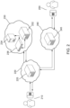
- Fig 2 is a diagrammatic view of one embodiment of a network system adapted to analyze communication data in real time.
- End point 210 is a device that enables a user to transmit and receive communications data, such as making and receiving telephone calls, sending and receiving messages, holding interactive multimedia conference calls, or some combination of the forgoing.
- End point 210 may include a telephone terminal, handset, cell phone, computer, smart phone, etc. Other suitable devices are described below.
- End point 210 is in communication with at least carrier network 220.
- Carrier network 220 may be a PSTN or an IP network that enables end point 210 to make and receive calls, send and receive messages, or other forms of communication.
- Carrier network 220 includes at least one network element 225 that can transmit and receive communications from devices such as end point 210 and other network elements (from within the carrier network 220 or outside of carrier network 220).
- network 230 includes several network elements.
- Network 230 includes at least one network element 232 that can transmit and receive telephone calls.
- network 230 may include any number of network elements 232 and other network elements necessary to operate a carrier network.
- Network element 232 may be a telephony switch or telephony gateway or other suitable network device or server (as is further described below).
- Network element 232 may be configured to transmit and receive telephone calls over either the PSTN (e.g., for TDM calls) or an IP network (e.g., for VoIP calls), or both.
- Network element 232 may include an SMS or MMS server or other messaging service that permits end points ( e.g ., 210, 250, etc.) to communicate with synchronous or asynchronous communications.
- Network element 232 may be a stand-alone messaging server. Where multiple network elements 232 are present in network 230, network elements 232 may be any suitable combinations of telephony or messaging switches, gateways, servers, etc. As shown in Fig. 2 , network 230 may be in communication with another network such as carrier network 220. It should be appreciated that network 230 may communicate with any suitable number of other networks and devices (not shown). While also not shown, network 230 may also be configured to communication with any number of end points (e.g., to receive or terminate calls or send and receive messages to and from these end points).
- end points e.g., to receive or terminate calls or send and receive messages to and from these end points.
- networks 220, 230, 240 may be in communication via any suitable type of network such as a PSTN network or an IP network such as the Internet.
- a PSTN network or an IP network such as the Internet.
- IP network such as the Internet.
- the limited number of networks and end points shown in Fig. 2 are merely to simplify illustration of how the real time analysis system works and in no way limit the quantity of networks and end points that can work with the real time analysis system.
- the number of networks and end points that can take advantage of the real time analysis system is limited only to the computing resources available relative to the quantity of specifically configured servers and connections devoted to the real time analysis.
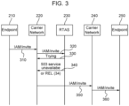
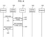
- Fig. 4 does not show all of the call setup and tear down signaling between end point 210 and end point 250. However, these aspects follow the standards used for SS7 and VoIP systems and should be apparent to one of ordinary skill in the art.
- the RTAS 230 may perform real time analysis on the message 520, as discussed above (e.g., apply an analysis of attributes associated with the message similar analyzing the attributes associated with a call), to determine whether or not fraud is detected in connection with the message from end point 210.
- RTAS 230 determined that the message from end point 210 was not fraudulent (using the methods described above).
- RTAS 230 send a rejection message 530 back to carrier network 220.
- the rejection message 530 may be in the form of a Resp Status: P_APPN (0x65) or some other suitable rejection message.
- Fig. 6 is a diagrammatic view of a message signaling flow of one embodiment of a network system that rejects a message and blocks the message from being sent to its intended destination.
- An illegitimate message sender associated with end point 210 attempts to send a message to a recipient associated with end point 250.
- the end point 210 sends a message 610 to carrier network 220.
- the type of message depends on the type of message, network, and equipment used by the callee at end point 210 and carrier network 220.
- the message 610 may be in the form of an SMS, MMS, or other suitable message.
- the message 610 may be received at a network element 225 of carrier network 220.
- carrier network 220 may be configured to send a message 620 to RTAS 230 for fraud detection processing by the real time analysis system.
- the message 620 may include a Submit or Deliver SM message.
- the RTAS 230 may perform real time analysis on the message 620, as discussed above, to determine whether or not fraud is detected in connection with the message from end point 210. In this embodiment, RTAS 230 determined that the message 620 from end point 210 is fraudulent (using the methods described above). Because the RTAS 230 determined that the message from end point 210 is fraudulent or associated with fraud, RTAS 230 sends a rejection message 630 back to carrier network 220.
- the rejection message 630 may be in the form of a Resp Status: P_APPN (0x66) or some other suitable rejection message.
- carrier network 220 Upon receiving the rejection message 630 from RTAS 230, carrier network 220 determines that the rejection message is actually associated with a determination that the message from end point 210 is fraudulent and should be blocked from being sent to the intended destination. Thus, carrier network 220 sends a rejection message 640 to end point 210.
- the rejection message 640 may be in the form of a Resp Status: P_APPN (0x66) or some other suitable rejection message.
- Fig. 6 does not show all of the message transmissions between end point 210 and the other network elements. However, these aspects follow the standards used for message transmission based on the type of messaging system used and should be apparent to one of ordinary skill in the art.
- RTAS real time analysis system
- network operators generally must pay other network operators to send communications traffic to networks and end points run by the other network operators. If fraudulent communications data traffic is sent to another network to reach the intended destination of the communications traffic, the sending network may be required to pay for the communications data traffic whether it was legitimate or not.
- communications traffic was reviewed after the communications were already completed. Data identifying that particular communications traffic was fraudulent was not detected until weeks or months after the fraudulent communications traffic was sent to another network and the costs for the fraudulent traffic were already incurred.
- RTAS architecture is cheaper and more efficient than preexisting systems.
- network operators create less records of communications traffic.
- communications data traffic is sent (and completed) to the intended destination, records of the communication are generated and stored. These records may be used, as noted above, for billing/invoicing and auditing purposes.
- fraudulent traffic is blocked, less records of the communication data traffic are generated because there is less communications data traffic.
- Communications data results in extremely large quantities of records.
- By reducing the amount of records generated less system server resources are used to create the records and less server and memory resources are used to store the records.
- this also reduces the amount of analysis that must be performed on the generated records.
- a reduction in the amount of analysis required results in less processor and memory intensive operations.
- a reduction in the amount of analysis required also results fewer disputes with other network operators over fees owed for communications data traffic passed to the other network operators to handle.
- RTAS architecture Another reason that the RTAS architecture is cheaper and more efficient than preexisting systems is that less network resources are used when fraudulent communications data traffic is blocked in real time. For example, if a fraudulent communications data is sent to an intended destination, many different system resources are used on one or more networks to deliver the communication data. Many communication devices will be used to transmit the communications data, which requires unnecessary use of processors, memory, and power. Physical ports of the telecommunication devices and network bandwidth are also used to unnecessarily deliver the communications data. All of the above are generally limited resources. When these limited resources are heavily used, network operators are forced to add additional capacity in terms of additional communications devices and bandwidth. If the network operators do not add additional resources in a timely manner, the existing communication devices may drop portions of the communications data or cause the communication devices to even fail. The RTAS architecture prevents unnecessary use of limited resources and prevents the need to purchase additional resources to meet a false demand generated by fraudulent communications data traffic.
- the RTAS architecture discussed herein works with existing communications and telephony systems to leverage/recycle certain communications or telecom principals and processes for new purposes.
- the RTAS architecture allows the fraud detection to be placed in the path of a communications transmission and analyze the communications transmission for fraud before the communications transmission incurs substantial costs.
- the RTAS architecture uses and repurposes rejection messages to communicate a determination of fraud or no fraud, whether or not a communications transmission is determined to be fraudulent.
- RTAS architecture described herein to perform real time analysis on communication data transmissions results in technological improvements over existing systems for a cheaper, more efficient, and more secure system.
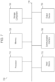
- Fig. 7 is a diagram of example components of computing devices 700 which may be used to implement various computer devices of the network system adapted to analyze communications data in real time described herein.
- computer devices 700 may be used to describe devices such as network elements 30, 35, 40 in carrier network 25 and network elements 232, 234, and 236 of RTAS 230 as well as other devices described herein.
- computing devices may be used to implement the systems and methods described in this document, as either a client or as a server or plurality of servers.
- Computing devices are intended to represent various forms of digital computers, such as laptops, desktops, workstations, personal digital assistants, servers, blade servers, mainframes, and other appropriate computers.
- Other computing devices may include various forms of mobile devices, such as personal digital assistants, cellular telephones, smartphones, and other similar computing devices.
- the components shown here, their connections and relationships, and their functions, are meant to be examples only, and are not meant to limit embodiments of the inventions described and/or claimed in this document.
- the processor may be implemented as a chipset of chips that include separate and multiple analog and digital processors. Additionally, the processor may be implemented using any of several architectures. For example, the processor may be an x86 processor, RISC (Reduced Instruction Set Computers) processor. The processor may coordinate with the other components of the device, such as control of user interfaces, applications run by the device, and wireless communication. Multiple processors or processors with multiple cores may also be used.
- the processor may communicate with a user through a control interface and display interface coupled to a display.
- the display may be, for example, an LED (Liquid Crystal Display) display, or other appropriate display technology.
- the display interface may comprise suitable circuitry for driving the display to present graphical and other information to a user.
- the control interface may receive commands from a user and convert them for submission to the processor.
- an external interface may be provided in communication with processor to enable near field communication with other devices.
- An external interface may provide, for example, for wireless and/or wired communication. Multiple interfaces may also be used
- the memory 720 may store information within the computing device.
- the memory is a volatile memory unit or units.
- the memory is a non-volatile memory unit or units.
- the memory may also be another form of computer-readable medium, such as a magnetic or optical disk.
- the storage device 730 is capable of providing mass storage for the computing device.
- the storage device may contain a computer-readable medium, such as a hard disk device, an optical disk device, or a tape device, a flash memory or other solid state memory device, or an array of devices, including devices in a storage area network or other configurations.
- the storage device may be anyone of the foregoing and be located remotely, such as in a cloud infrastructure.
- a computer program product can be tangibly embodied in an information carrier.
- the computer program product may also contain instructions that, when executed, perform one or more methods, such as those described above.
- the information carrier is a computer or machine readable medium, such as the memory 720, the storage device 730, or memory on processor 710.
- the computing system can include clients and servers.
- a client and server are generally remote from each other and typically interact through a communication network.
- the relationship of client and server arises through computer programs running on the respective computers and having a client-server relationship to each other.
Landscapes
- Engineering & Computer Science (AREA)
- Signal Processing (AREA)
- Computer Security & Cryptography (AREA)
- Computer Networks & Wireless Communication (AREA)
- General Engineering & Computer Science (AREA)
- Computer Hardware Design (AREA)
- Computing Systems (AREA)
- Software Systems (AREA)
- Theoretical Computer Science (AREA)
- Physics & Mathematics (AREA)
- General Physics & Mathematics (AREA)
- Business, Economics & Management (AREA)
- Accounting & Taxation (AREA)
- Telephonic Communication Services (AREA)
- Data Exchanges In Wide-Area Networks (AREA)
Applications Claiming Priority (3)
| Application Number | Priority Date | Filing Date | Title |
|---|---|---|---|
| US201662320627P | 2016-04-11 | 2016-04-11 | |
| PCT/US2017/026799 WO2017180512A1 (fr) | 2016-04-11 | 2017-04-10 | Système et procédé d'analyse de fraude en temps réel sur des données de communications |
| EP17782916.5A EP3443487B1 (fr) | 2016-04-11 | 2017-04-10 | Système et procédé d'analyse de fraude en temps réel sur des données de communications |
Related Parent Applications (2)
| Application Number | Title | Priority Date | Filing Date |
|---|---|---|---|
| EP17782916.5A Division EP3443487B1 (fr) | 2016-04-11 | 2017-04-10 | Système et procédé d'analyse de fraude en temps réel sur des données de communications |
| EP17782916.5A Division-Into EP3443487B1 (fr) | 2016-04-11 | 2017-04-10 | Système et procédé d'analyse de fraude en temps réel sur des données de communications |
Publications (2)
| Publication Number | Publication Date |
|---|---|
| EP4539513A2 true EP4539513A2 (fr) | 2025-04-16 |
| EP4539513A3 EP4539513A3 (fr) | 2025-06-25 |
Family
ID=60042656
Family Applications (2)
| Application Number | Title | Priority Date | Filing Date |
|---|---|---|---|
| EP17782916.5A Active EP3443487B1 (fr) | 2016-04-11 | 2017-04-10 | Système et procédé d'analyse de fraude en temps réel sur des données de communications |
| EP25159649.0A Pending EP4539513A3 (fr) | 2016-04-11 | 2017-04-10 | Système et procédé d'analyse de fraude en temps réel de données de communication |
Family Applications Before (1)
| Application Number | Title | Priority Date | Filing Date |
|---|---|---|---|
| EP17782916.5A Active EP3443487B1 (fr) | 2016-04-11 | 2017-04-10 | Système et procédé d'analyse de fraude en temps réel sur des données de communications |
Country Status (5)
| Country | Link |
|---|---|
| US (4) | US10548016B2 (fr) |
| EP (2) | EP3443487B1 (fr) |
| AU (1) | AU2017249170B2 (fr) |
| SG (1) | SG11201808725VA (fr) |
| WO (1) | WO2017180512A1 (fr) |
Families Citing this family (10)
| Publication number | Priority date | Publication date | Assignee | Title |
|---|---|---|---|---|
| EP3443487B1 (fr) * | 2016-04-11 | 2025-04-09 | Tata Communications (America) Inc. | Système et procédé d'analyse de fraude en temps réel sur des données de communications |
| US11381612B2 (en) * | 2018-06-08 | 2022-07-05 | T-Mobile Usa, Inc. | Voice over long-term evolution (VoLTE) call normalization and alert policy system |
| TR201820331A2 (tr) * | 2018-12-25 | 2019-01-21 | Turkcell Teknoloji Arastirma Ve Gelistirme Anonim Sirketi | İki̇nci̇ bi̇r numara üzeri̇nden çağri başlatilmasini ve alinmasini sağlayan bi̇r si̇stem |
| US10757252B1 (en) | 2019-06-25 | 2020-08-25 | Youmail, Inc. | Identifying, screening, and blocking of calls from problematic telecommunications carriers and number blocks |
| EP3817351A1 (fr) * | 2019-10-28 | 2021-05-05 | Sigos Bvba | Système permettant d'effectuer une analyse et de bloquer des identités d'abonnés frauduleuses dans un réseau de communication |
| FR3116688B1 (fr) | 2020-11-24 | 2023-11-03 | Araxxe | Procede et systeme de lutte contre la fraude telephonique aux appels-pieges |
| US11689542B2 (en) | 2021-07-07 | 2023-06-27 | International Business Machines Corporation | Detecting, verifying, and preventing unauthorized use of a voice over internet protocol service |
| CN114501462A (zh) * | 2022-02-10 | 2022-05-13 | 上海闻泰信息技术有限公司 | 诈骗来电识别方法、装置、电子设备及存储介质 |
| US12549599B2 (en) | 2023-06-29 | 2026-02-10 | Bank Of America Corporation | System and method for intercepting and classifying suspicious text messages between user devices |
| US12437066B2 (en) | 2023-06-29 | 2025-10-07 | Bank Of America Corporation | System and method for classifying suspicious text messages received by a user device |
Citations (1)
| Publication number | Priority date | Publication date | Assignee | Title |
|---|---|---|---|---|
| US6404864B1 (en) | 1999-06-05 | 2002-06-11 | Itxc Corp | Article comprising a distributed call monitoring, evaluation and routing system and method therefor |
Family Cites Families (8)
| Publication number | Priority date | Publication date | Assignee | Title |
|---|---|---|---|---|
| US7756930B2 (en) * | 2004-05-28 | 2010-07-13 | Ironport Systems, Inc. | Techniques for determining the reputation of a message sender |
| US7155243B2 (en) | 2004-06-15 | 2006-12-26 | Tekelec | Methods, systems, and computer program products for content-based screening of messaging service messages |
| US7773667B2 (en) * | 2005-07-14 | 2010-08-10 | Agere Systems Inc. | Pseudo asynchronous serializer deserializer (SERDES) testing |
| US20070143422A1 (en) | 2005-12-21 | 2007-06-21 | Yigang Cai | Phonebook use to filter unwanted telecommunications calls and messages |
| US8194581B1 (en) | 2008-11-04 | 2012-06-05 | Cellco Partnership | Account holder notification for an infracting mobile station or mobile directory number (MDN) |
| US8588744B2 (en) * | 2008-11-26 | 2013-11-19 | Ringcentral, Inc. | Fraud prevention techniques |
| US9060057B1 (en) * | 2013-03-07 | 2015-06-16 | Serdar Artun Danis | Systems and methods for caller ID authentication, spoof detection and list based call handling |
| EP3443487B1 (fr) * | 2016-04-11 | 2025-04-09 | Tata Communications (America) Inc. | Système et procédé d'analyse de fraude en temps réel sur des données de communications |
-
2017
- 2017-04-10 EP EP17782916.5A patent/EP3443487B1/fr active Active
- 2017-04-10 US US16/090,720 patent/US10548016B2/en active Active
- 2017-04-10 EP EP25159649.0A patent/EP4539513A3/fr active Pending
- 2017-04-10 SG SG11201808725VA patent/SG11201808725VA/en unknown
- 2017-04-10 WO PCT/US2017/026799 patent/WO2017180512A1/fr not_active Ceased
- 2017-04-10 AU AU2017249170A patent/AU2017249170B2/en active Active
-
2019
- 2019-11-06 US US16/676,185 patent/US10993115B2/en active Active
- 2019-11-07 US US16/677,447 patent/US10873860B2/en active Active
-
2021
- 2021-04-26 US US17/240,454 patent/US11395147B2/en active Active
Patent Citations (1)
| Publication number | Priority date | Publication date | Assignee | Title |
|---|---|---|---|---|
| US6404864B1 (en) | 1999-06-05 | 2002-06-11 | Itxc Corp | Article comprising a distributed call monitoring, evaluation and routing system and method therefor |
Also Published As
| Publication number | Publication date |
|---|---|
| AU2017249170B2 (en) | 2022-02-17 |
| US11395147B2 (en) | 2022-07-19 |
| WO2017180512A1 (fr) | 2017-10-19 |
| US20200077270A1 (en) | 2020-03-05 |
| SG11201808725VA (en) | 2018-11-29 |
| US10548016B2 (en) | 2020-01-28 |
| EP3443487A4 (fr) | 2019-11-20 |
| US20210250768A1 (en) | 2021-08-12 |
| EP3443487A1 (fr) | 2019-02-20 |
| CA3019833A1 (fr) | 2017-10-19 |
| US20190124516A1 (en) | 2019-04-25 |
| US10873860B2 (en) | 2020-12-22 |
| US10993115B2 (en) | 2021-04-27 |
| EP4539513A3 (fr) | 2025-06-25 |
| US20200077271A1 (en) | 2020-03-05 |
| EP3443487B1 (fr) | 2025-04-09 |
| AU2017249170A1 (en) | 2018-11-01 |
Similar Documents
| Publication | Publication Date | Title |
|---|---|---|
| US11395147B2 (en) | System and method for real time fraud analysis of communications data | |
| US11171864B2 (en) | Determining a time to permit a communications session to be conducted | |
| US11190638B2 (en) | Detection and prevention of unwanted calls in a telecommunications system | |
| US11546740B2 (en) | Routing of toll-free numbers and text messages using a toll-free exchange | |
| US9191351B2 (en) | Real-time fraudulent traffic security for telecommunication systems | |
| US9807249B2 (en) | Routing of toll-free numbers using a toll-free exchange | |
| US8825003B2 (en) | Methods, systems, and computer readable media for providing variable rate prepaid telecommunication services utilizing a weighting function | |
| CA3019833C (fr) | Systeme et procede d'analyse de fraude en temps reel sur des donnees de communications | |
| US20050143050A1 (en) | Method for billing a communications link between communications terminals | |
| WO2025013014A1 (fr) | Procédé et système de facturation d'un utilisateur dans un réseau de télécommunication | |
| KR101605688B1 (ko) | 무료통화기능이 포함된 멀티미디어 네트워크 서비스 시스템 | |
| KR101630838B1 (ko) | 불법 우회 과금 검출 방법 | |
| Sterman | Real-time billing in sip |
Legal Events
| Date | Code | Title | Description |
|---|---|---|---|
| PUAI | Public reference made under article 153(3) epc to a published international application that has entered the european phase |
Free format text: ORIGINAL CODE: 0009012 |
|
| STAA | Information on the status of an ep patent application or granted ep patent |
Free format text: STATUS: THE APPLICATION HAS BEEN PUBLISHED |
|
| AC | Divisional application: reference to earlier application |
Ref document number: 3443487 Country of ref document: EP Kind code of ref document: P |
|
| AK | Designated contracting states |
Kind code of ref document: A2 Designated state(s): AL AT BE BG CH CY CZ DE DK EE ES FI FR GB GR HR HU IE IS IT LI LT LU LV MC MK MT NL NO PL PT RO RS SE SI SK SM TR |
|
| REG | Reference to a national code |
Ref country code: DE Ref legal event code: R079 Free format text: PREVIOUS MAIN CLASS: H04W0004240000 Ipc: G04R0020140000 |
|
| PUAL | Search report despatched |
Free format text: ORIGINAL CODE: 0009013 |
|
| AK | Designated contracting states |
Kind code of ref document: A3 Designated state(s): AL AT BE BG CH CY CZ DE DK EE ES FI FR GB GR HR HU IE IS IT LI LT LU LV MC MK MT NL NO PL PT RO RS SE SI SK SM TR |
|
| RIC1 | Information provided on ipc code assigned before grant |
Ipc: H04W 4/24 20240101ALI20250522BHEP Ipc: H04L 9/40 20220101ALI20250522BHEP Ipc: H04W 4/14 20090101ALI20250522BHEP Ipc: G06F 21/50 20130101ALI20250522BHEP Ipc: H04M 3/436 20060101ALI20250522BHEP Ipc: H04M 15/00 20240101ALI20250522BHEP Ipc: G04R 20/14 20130101AFI20250522BHEP |
|
| STAA | Information on the status of an ep patent application or granted ep patent |
Free format text: STATUS: REQUEST FOR EXAMINATION WAS MADE |
|
| 17P | Request for examination filed |
Effective date: 20251223 |
|
| GRAP | Despatch of communication of intention to grant a patent |
Free format text: ORIGINAL CODE: EPIDOSNIGR1 |
|
| STAA | Information on the status of an ep patent application or granted ep patent |
Free format text: STATUS: GRANT OF PATENT IS INTENDED |