EP4539567A1 - Procédé de mesure et appareil de mesure - Google Patents
Procédé de mesure et appareil de mesure Download PDFInfo
- Publication number
- EP4539567A1 EP4539567A1 EP22961689.1A EP22961689A EP4539567A1 EP 4539567 A1 EP4539567 A1 EP 4539567A1 EP 22961689 A EP22961689 A EP 22961689A EP 4539567 A1 EP4539567 A1 EP 4539567A1
- Authority
- EP
- European Patent Office
- Prior art keywords
- symbol
- radio frame
- moment
- link
- time difference
- Prior art date
- Legal status (The legal status is an assumption and is not a legal conclusion. Google has not performed a legal analysis and makes no representation as to the accuracy of the status listed.)
- Pending
Links
Images






Classifications
-
- G—PHYSICS
- G01—MEASURING; TESTING
- G01S—RADIO DIRECTION-FINDING; RADIO NAVIGATION; DETERMINING DISTANCE OR VELOCITY BY USE OF RADIO WAVES; LOCATING OR PRESENCE-DETECTING BY USE OF THE REFLECTION OR RERADIATION OF RADIO WAVES; ANALOGOUS ARRANGEMENTS USING OTHER WAVES
- G01S11/00—Systems for determining distance or velocity not using reflection or reradiation
- G01S11/02—Systems for determining distance or velocity not using reflection or reradiation using radio waves
-
- G—PHYSICS
- G01—MEASURING; TESTING
- G01S—RADIO DIRECTION-FINDING; RADIO NAVIGATION; DETERMINING DISTANCE OR VELOCITY BY USE OF RADIO WAVES; LOCATING OR PRESENCE-DETECTING BY USE OF THE REFLECTION OR RERADIATION OF RADIO WAVES; ANALOGOUS ARRANGEMENTS USING OTHER WAVES
- G01S13/00—Systems using the reflection or reradiation of radio waves, e.g. radar systems; Analogous systems using reflection or reradiation of waves whose nature or wavelength is irrelevant or unspecified
- G01S13/74—Systems using reradiation of radio waves, e.g. secondary radar systems; Analogous systems
- G01S13/76—Systems using reradiation of radio waves, e.g. secondary radar systems; Analogous systems wherein pulse-type signals are transmitted
- G01S13/765—Systems using reradiation of radio waves, e.g. secondary radar systems; Analogous systems wherein pulse-type signals are transmitted with exchange of information between interrogator and responder
-
- G—PHYSICS
- G01—MEASURING; TESTING
- G01S—RADIO DIRECTION-FINDING; RADIO NAVIGATION; DETERMINING DISTANCE OR VELOCITY BY USE OF RADIO WAVES; LOCATING OR PRESENCE-DETECTING BY USE OF THE REFLECTION OR RERADIATION OF RADIO WAVES; ANALOGOUS ARRANGEMENTS USING OTHER WAVES
- G01S13/00—Systems using the reflection or reradiation of radio waves, e.g. radar systems; Analogous systems using reflection or reradiation of waves whose nature or wavelength is irrelevant or unspecified
- G01S13/87—Combinations of radar systems, e.g. primary radar and secondary radar
- G01S13/878—Combination of several spaced transmitters or receivers of known location for determining the position of a transponder or a reflector
-
- G—PHYSICS
- G01—MEASURING; TESTING
- G01S—RADIO DIRECTION-FINDING; RADIO NAVIGATION; DETERMINING DISTANCE OR VELOCITY BY USE OF RADIO WAVES; LOCATING OR PRESENCE-DETECTING BY USE OF THE REFLECTION OR RERADIATION OF RADIO WAVES; ANALOGOUS ARRANGEMENTS USING OTHER WAVES
- G01S5/00—Position-fixing by co-ordinating two or more direction or position line determinations; Position-fixing by co-ordinating two or more distance determinations
- G01S5/0009—Transmission of position information to remote stations
-
- G—PHYSICS
- G01—MEASURING; TESTING
- G01S—RADIO DIRECTION-FINDING; RADIO NAVIGATION; DETERMINING DISTANCE OR VELOCITY BY USE OF RADIO WAVES; LOCATING OR PRESENCE-DETECTING BY USE OF THE REFLECTION OR RERADIATION OF RADIO WAVES; ANALOGOUS ARRANGEMENTS USING OTHER WAVES
- G01S7/00—Details of systems according to groups G01S13/00, G01S15/00, G01S17/00
- G01S7/003—Transmission of data between radar, sonar or lidar systems and remote stations
- G01S7/006—Transmission of data between radar, sonar or lidar systems and remote stations using shared front-end circuitry, e.g. antennas
-
- H—ELECTRICITY
- H04—ELECTRIC COMMUNICATION TECHNIQUE
- H04L—TRANSMISSION OF DIGITAL INFORMATION, e.g. TELEGRAPHIC COMMUNICATION
- H04L27/00—Modulated-carrier systems
- H04L27/26—Systems using multi-frequency codes
- H04L27/2601—Multicarrier modulation systems
- H04L27/2602—Signal structure
- H04L27/261—Details of reference signals
- H04L27/2613—Structure of the reference signals
-
- H—ELECTRICITY
- H04—ELECTRIC COMMUNICATION TECHNIQUE
- H04W—WIRELESS COMMUNICATION NETWORKS
- H04W24/00—Supervisory, monitoring or testing arrangements
- H04W24/08—Testing, supervising or monitoring using real traffic
-
- H—ELECTRICITY
- H04—ELECTRIC COMMUNICATION TECHNIQUE
- H04W—WIRELESS COMMUNICATION NETWORKS
- H04W64/00—Locating users or terminals or network equipment for network management purposes, e.g. mobility management
-
- H—ELECTRICITY
- H04—ELECTRIC COMMUNICATION TECHNIQUE
- H04W—WIRELESS COMMUNICATION NETWORKS
- H04W72/00—Local resource management
- H04W72/04—Wireless resource allocation
- H04W72/044—Wireless resource allocation based on the type of the allocated resource
- H04W72/0446—Resources in time domain, e.g. slots or frames
Definitions
- Embodiments of this application relate to the communication field, and in particular, to a measurement method and a measurement apparatus.
- a distance between devices is determined based on a sending time and a receiving time of a subframe transmitted between the devices.
- a time length of one subframe is 1 millisecond.
- this application provides a measurement method, a measurement apparatus, a measurement device, a computer-readable storage medium, a computer program product, and the like, to improve accuracy of measuring a distance between devices.
- this application provides a measurement method.
- the method includes: A first device sends a first symbol; the first device receives a second symbol from a second device, where the first symbol and the second symbol are carried on a same radio frame or different radio frames; and the first device determines a first time difference, where the first time difference is a time interval between a first moment at which the first device sends the first symbol and a second moment at which the first device receives the second symbol, and the first time difference is used to determine a distance between the first device and the second device.
- both the first symbol and the second symbol may be referred to as ranging symbols.
- the first symbol When the first device is a master node and the second device is a slave node, the first symbol may be referred to as a G link ranging symbol, and the second symbol may be referred to as a T link ranging symbol.
- the first symbol When the first device is a slave node and the second device is a master node, the first symbol may be referred to as a T link ranging symbol, and the second symbol may be referred to as a G link ranging symbol.
- the first time difference is an interval between a sending time and a receiving time of a ranging symbol, and can more accurately indicate transmission duration of a signal between the devices, a more accurate inter-device distance can be determined based on the first time difference.
- the method may further include: The first device sends time information to the second device, where the time information is used to determine the first time difference, and the first time difference is the time interval between the first moment at which the first device sends the first symbol and the second moment at which the first device receives the second symbol.
- a sequence of receiving the second time information by the first device and determining the first time difference by the first device is not limited.
- u is any integer from a to b, a is a positive integer greater than 1, b is a positive integer less than 39, and a is less than b.
- the second symbol may be carried on the resource that is in the radio frame and that is used to transmit the G link symbol and/or the resource that is in the radio frame and that is used to transmit the SG symbol
- the first symbol may be carried on the resource that is in the radio frame and that is used to transmit the ST symbol and/or the resource that is in the radio frame and that is used to transmit the T link symbol.
- the first symbol is carried on the resource that is in a first radio frame and that is used to transmit the T link symbol
- the second symbol is carried on a resource that is in a second radio frame and that is used to transmit the G link symbol
- a GAP exists between the first symbol and the second symbol
- the second symbol is carried on the resource that is in the first radio frame and that is used to transmit the T link symbol
- the first symbol is carried on the resource that is in the second radio frame and that is used to transmit the G link symbol
- a GAP exists between the first symbol and the second symbol
- the method when the first device receives, from the second device, the first time information used to determine the second time difference, and determines the distance between the first device and the second device based on the first time difference and the second time difference, the method further includes: The first device receives measurement information from the second device, where the measurement information indicates a measurement exchange sequence number corresponding to the first time information.
- the measurement exchange sequence number indicates a sequence number that is of a current operation of exchanging the first time information between the first device and the second device and that is in all exchange operations of all time information exchanged between the first device and the second device for determining the distance between the first device and the second device.
- the first device can accurately associate time information obtained by the first device through exchange with the second device with a time difference that is obtained by the first device through measurement and that has a same measurement sequence number, so as to obtain an accurate distance.
- the method when the first device sends, to the second device, the first time information used to determine the first time difference, so that the second device determines the distance between the first device and the second device based on the first time difference and the second time difference, the method further includes: The first device sends measurement information to the second device, where the measurement information indicates a measurement sequence number corresponding to the first time information.
- the measurement sequence number indicates a sequence number that is of a current operation of exchanging the first time information between the first device and the second device and that is in all exchange operations of all time information exchanged between the first device and the second device for determining the distance between the first device and the second device.
- the second device can accurately associate time information obtained by the second device through exchange with the second device with a time difference that is obtained by the second device through measurement and that has a same measurement sequence number, so as to obtain an accurate distance.
- the first symbol may be an S th one in one or more ranging symbols sent by the first device in one distance measurement process
- the second symbol may be an S th one in one or more ranging symbols received by the first device in one distance measurement process.
- the first device may send N first symbols in one distance measurement process, where the first moment is a sending moment of the 1st first symbol in the N first symbols, and N is a positive integer.
- the first device may receive M second symbols in this distance measurement process, where the second moment is a receiving moment of the 1st received second symbol in the M second symbols, and M is a positive integer.
- the third moment may be a moment at which the second device receives the 1st symbol in the N first symbols
- the fourth moment is a moment at which the second device sends the 1st second symbol in the M second symbols.
- the first moment may be a sending moment of a starting point of the CP of the first symbol.
- the third moment may be a moment at which the second device receives the starting point of the CP of the first symbol.
- the second moment may be a receiving moment of a starting point of the CP of the second symbol.
- the fourth moment may be a moment at which the second device sends the starting point of the CP of the second symbol.
- the second moment is a sending moment at which the first device receives a starting point of the second symbol.
- the fourth moment may be a moment at which the second device sends the starting point of the second symbol.
- the third moment is a moment at which the starting point of the first symbol arrives at the second antenna connector of the second device
- the fourth moment may be a moment at which the starting point of the second symbol arrives at the second antenna connector
- the first moment may be a moment at which the starting point of the CP of the first symbol arrives at the first antenna connector of the first device, and the second moment may be a moment at which the starting point of the CP of the second symbol arrives at the first antenna connector.
- the third moment may be a moment at which the starting point of the CP of the first symbol arrives at the second antenna connector of the second device
- the fourth moment may be a moment at which the starting point of the CP of the second symbol arrives at the second antenna connector of the second device.
- the method further includes: The first device sends first configuration information to the second device, where the first configuration information indicates a time-frequency resource of the first symbol and a time-frequency resource of the second symbol.
- the first device configures the time-frequency resource of the first symbol and the time-frequency resource of the second symbol for the second device, so that the second device receives the first symbol based on time-frequency resource information of the first symbol and sends the second symbol based on time-frequency resource information of the second symbol.
- the method may further include: The first device receives first configuration information from the second device, where the first configuration information indicates a time-frequency resource of the first symbol and a time-frequency resource of the second symbol.
- the apparatus may be a device, or may be a chip used in a device.
- this application provides a computer-readable storage medium.
- the computer-readable storage medium stores instructions, and when the instructions are run on an electronic device or a computer, the electronic device or the computer is enabled to perform the method in the first aspect.
- positioning anchors may be respectively deployed on four corners of a vehicle, and positioning anchors are deployed on a center console, rear view mirrors, and a ceiling (that is, a top inside the vehicle) of the vehicle, to position a vehicle key used as a to-be-positioned node.
- the vehicle key may include a vehicle key that has a positioning function in a conventional form, or may include a mobile phone, a wearable device, or the like that may be used to unlock a vehicle, or serve as a vehicle key.
- the positioning anchor may also be referred to as a positioning node, a positioning base station, or a positioning beacon (beacon), and may be referred to as an anchor (anchor) for short.
- the to-be-positioned node may be referred to as a positioning tag (tag) or a measured node, and may be referred to as a tag for short.
- the positioning anchors are deployed on the corners of the vehicle, the central control console, the rear view mirrors, or the ceiling is merely an example.
- An in-vehicle wireless device such as a display screen, a microphone, a speaker, a camera, and a T-BOX inside the vehicle, or a camera of a 360 all-around application outside the vehicle may also be reused as a positioning anchor.
- any node may act as a node G.
- the node G may be a vehicle key, and all anchors in the vehicle are T nodes.
- the node G is any anchor in the vehicle, and other anchors and the vehicle key are all T nodes.
- a distance between each of the plurality of anchors and the to-be-positioned node may be measured, and the to-be-positioned node (the vehicle key) is positioned based on the measured distances.
- a method for positioning the to-be-positioned node based on the measured distances refer to a distance-based positioning method in the existing communication field, for example, a trilateration method (Trilateration) or a multilateration method (Multilateration). Details are not described herein again.
- Trilateration Trilateration
- Multilateration multilateration method
- the following describes a method for measuring a distance/angle (for example, an angle of arrival) between an anchor and a to-be-positioned node.
- a distance/angle for example, an angle of arrival
- FIG. 3 is a schematic flowchart of a measurement method according to an embodiment of this application. It may be understood that FIG. 3 is merely an example, and the measurement method in this application may include more or similar steps.
- a first device may be the device 101 in FIG. 1
- a second device may be the device 102 in FIG. 1 ; or the first device may be any anchor in FIG. 2 , and the second device may be the positioned node in FIG. 2 .
- S310 The first device sends a first symbol.
- the second device receives the first symbol.
- a radio frame that carries the first symbol is a radio frame in a SparkLink wireless communication technology.
- Abasic version of the SparkLink wireless communication standard includes transmission frame structures of a super frame and a radio frame.
- a period of the super frame is 1 millisecond (ms)
- each super frame includes 48 radio frames
- a length of each radio frame may be 20.833 microseconds
- one radio frame may include a downlink data symbol, an uplink data symbol, a system overhead symbol (a system overhead G symbol or a system overhead T symbol), and an uplink/downlink switching interval.
- the downlink data symbol may also be referred to as a G link symbol, which is referred to as a G symbol for short, and the G symbol is transmitted on a G link.
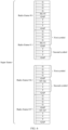
- FIG. 4 A diagram of structures of a super frame and radio frames is shown in FIG. 4 .
- one super frame includes 48 radio frames, the radio frames are numbered from 0, and one radio frame includes four G symbol resources, one SG symbol resource or one ST symbol resource, three T symbol resources, and two GAPs.
- the G symbol resource is used for a device used as a management node to send a data symbol, and the data symbol may be referred to as a G symbol.
- the SG symbol resource is used for the device used as the management node to send a system overhead symbol, and the system overhead symbol is referred to as an SG symbol.
- the ST symbol resource is used for a device used as a slave node to send a system overhead symbol, and the system overhead symbol is referred to as an ST symbol.
- the T symbol resource is used for the device used as the slave node to send a data symbol, and the data symbol is referred to as a T symbol.
- the GAP is used for switching between sending and receiving of the device.
- FIG. 4 is merely an example.
- a quantity of radio frames included in one super frame, and quantities of G symbol resources, SG symbol resources, ST symbol resources, T symbol resources, and GAPs included in one radio frame may not be limited thereto.
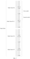
- the first symbol is carried on all or some resources that are in the radio frame #46 and that are used to transmit a G link symbol
- the second symbol is carried on all or some resources that are in the radio frame #46 and that are used to transmit a T link symbol, and a resource used to transmit an ST symbol.
- measurement when the first symbol and the second symbol are carried on a same radio frame, measurement may be completed in a single radio frame.
- ranging/angle measurement may be completed once in duration (20.83 ⁇ s) of one radio frame, and a measurement latency is extremely low.
- a frame structure that includes both a G symbol and a T symbol and that is of one radio frame is fully used, so that extremely low latency performance is provided, or more measurement results can be provided within a specific measurement time, thereby providing more sampling data for subsequent post-processing of positioning such as extended Kalman filtering.
- FIG. 7 is a diagram of transmission of a ranging symbol according to another embodiment of this application.
- the first symbol is carried on a radio frame #K+1
- the second symbol is carried on a radio frame #K
- K is an integer less than 48.
- the first symbol is carried on all or some resources that are in the radio frame #K+1 and that are used to transmit a G link symbol and/or an SG symbol
- the second symbol is carried on all or some resources that are in the radio frame #K and that are used to transmit a T link symbol.
- the radio frame #K and the radio frame #K+1 are examples, and the radio frames carrying the first symbol and the second symbol may be consecutive or inconsecutive.
- FIG. 4 to FIG. 7 are frame structures of a super frame, and a horizontal coordinate in each of FIG. 4 to FIG. 7 is time.
- ranging may be performed based on a quantity of devices by using radio frames with different ratios of G symbol resources to T symbol resources (that is, different radio frame structures).
- the first device determines a first time difference, where the first time difference is a time interval between a first moment at which the first device sends the first symbol and a second moment at which the first device receives the second symbol, and the first time difference is used to determine a distance between the first device and the second device.
- the first device obtains a time point at which the first symbol is sent, and denotes the time as the first moment; and obtains a time point at which the second symbol is received, and denotes the time as the second moment; and calculates a difference between the first time t1 and the second time t2, to obtain the first time difference.
- the first time difference should be a positive number, that is, the first time difference is t2-t1, and the second time is after the first time.
- the second device obtains first time information, where the first time information is used to determine a second time difference, and the second time difference is a time interval between a third moment at which the second device receives the first symbol and a fourth moment at which the second device sends the second symbol.
- the first device may estimate the first time difference based on t 1 ', t 2 ', and T cali,G .
- T cali,G represents a calibration time parameter of the first device, and may be a sum of delays introduced by a radio frequency (RF) transmit channel and an RF receive channel of the first device and a baseband processing delay when the first device receives the second symbol.
- RF radio frequency
- An example method for determining u is as follows: Within a specific time range, a positive integer is randomly selected as a value of u in a closed interval [a, b], so as to generate, according to the foregoing formula, the ZC sequence for RTT ranging exchange.
- a node G and a node T determine the value of u in advance by exchanging a message. Therefore, in an RTT ranging process, u is a preset value known to both the node G and the node T.
- the value of u may be adjusted based on a time period T, that is, a positive integer value is randomly re-selected as a new value of u within [a, b] at intervals of T, so that another device cannot continuously listen to the ZC sequence that has a random change.
- a random ZC sequence can be obtained by randomly selecting the value of u, and different ZC sequences can also avoid generating large measurement signal interference between the ZC sequence and a neighboring device.
- a positioning reference signal different from the first training signal and the second training signal may be obtained, and a same waveform may be avoided from being used with the FTS and the STS.
- the ranging symbol carrying the foregoing ZC sequence may be referred to as a positioning reference signal (Positioning Reference Signal, PRS).
- PRS Positioning Reference Signal
- an existing channel state information reference signal (CSI-RS) or sounding reference signal (SRS) in the SLB may also be used as the ranging symbol.
- CSI-RS channel state information reference signal
- SRS sounding reference signal
- a unit of each measurement time may be a picosecond (ps).
- a unit of the first moment, the second moment, the third moment, and the fourth moment may be ps.
- a unit of the first time difference and the second time difference may be ps.
- the first device may send first configuration information to the second device.
- the first configuration information may include one or more of the following information: a quantity of times of measurement, an identifier of a first radio frame in each measurement, a time-frequency resource of the first symbol in each measurement, an identifier of a second radio frame in each measurement, and a time-frequency resource of the second symbol in each measurement.
- An example format of the first configuration information is shown in the following table. Field Description P Quantity of times of measurement, where P is a positive integer.
- Radio frame identifier 1-1 An identifier or a number of a radio frame on which the first symbol is located in the first measurement, where an example of the first symbol is a G link ranging symbol; Bitmap (bitmap) Indicating a resource that is in the radio frame identifier 1-1 and that is used to carry the first symbol, where the bitmap may include R 1 bits, R 1 is a quantity of symbol resources in a radio frame indicated by the radio frame identifier 1-1, the R 1 bits are in a one-to-one correspondence with R 1 symbol resources in the radio frame, a symbol resource corresponding to a bit with a value of 1 carries the first symbol, and a symbol resource corresponding to a bit with a value of 0 does not carry the first symbol; Radio frame identifier 1-2 An identifier or a number of a radio frame on which the second symbol is located in the first measurement, where an example of the second symbol is a T link ranging symbol; Bitmap Indicating a symbol resource that is in a radio frame indicated by the
- FIG. 10 is a diagram of transmission of a ranging symbol according to still another embodiment of this application.
- different T symbol resources may be used to measure distances for different devices.
- a T1 symbol resource, a T2 symbol resource, and a T3 symbol resource are respectively used by a device 1, a device 2, and a device 3 to send the second symbol.
- T symbol resources in FIG. 10 are used by the three devices to separately send respective T ranging symbols is merely an example.
- a quantity 3 of devices does not constitute a limitation on a quantity of ranging devices associated with the T symbol resources.
- T symbol resources in a same radio frame may be used by W devices to send respective T ranging symbols, provided that W is a positive integer greater than 1.
- T symbol resources in one radio frame may not only be used to measure a distance between one G node and one T node, but also be used to measure a distance between each of a plurality of T nodes and the G node, that is, used for multi-user distance measurement or multi-device distance measurement.
- the first device used as the G node may group the plurality of T nodes into one group of nodes, and send group configuration information to the group of T nodes.
- the group configuration information may include a time-frequency resource used by the G node to send a G ranging symbol (for example, the first symbol) and a T symbol resource used by each T node in the group of nodes to send a T ranging symbol (for example, the second symbol).
- each T node may obtain a related time difference based on a resource indicated by the group configuration information, to measure a distance between the T node and the G node.
- time information used to determine a time difference is collectively referred to as time feedback information.
- the first time information is the time feedback information.
- the second device may send the time difference in a format shown in the following table.
- Field Description Q A quantity of time differences that are fed back; Time difference 1 Indicating the 1st time difference in Q time differences fed back by the device; ... ... Time difference p Indicating a q th time difference in the Q time differences fed back by the device, where q is a positive integer less than or equal to Q; ... ...
- FIG. 11 is a schematic flowchart of a ranging method according to another embodiment of this application.
- the method may include S310, S320, S330, S340, S325, S350, S341, S342, S351, and S370. It may be understood that the execution sequence in the implementation shown in FIG. 11 is merely an example. This is not limited in this embodiment of this application.
- S325 The first device sends a third symbol.
- the third symbol may also be referred to as a ranging symbol.
- the first symbol and the second symbol are carried on the first radio frame
- the third symbol is carried on the second radio frame
- the second radio frame is located after the first radio frame.
- the first device determines a third time difference, where the third time difference is a time interval between the second moment at which the first device receives the second symbol and a fifth moment at which the first device sends the third symbol.
- S351 The second device sends the second time information.
- the first device receives the second time information.
- the first device and the second device determine the distance between the first device and the second device based on the first time difference, the second time difference, the third time difference, and the fourth time difference.
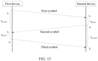
- FIG. 12 is a diagram of transmission of a ranging symbol according to an embodiment of this application. As shown in FIG. 12 , G symbol resources and T symbol resources in the radio frame #K and G symbol resources in the radio frame #K+1 carry ranging symbols.
- the G symbol resources in the radio frame #K carry the first symbol
- the T symbol resources in the radio frame #K carry the second symbol
- the G symbol resources in the radio frame #K+1 carry the third symbol.
- a diagram of interactive transmission of the first symbol, the second symbol, and the third symbol in this example is shown in FIG. 13 .
- Radio frame identifier p-1 An identifier or a number of a radio frame on which the first symbol is located in a p th measurement, where p is a positive integer less than or equal to P; Bitmap Indicating a resource that is in a radio frame indicated by the radio frame identifier p-1 and that carries the first symbol, where the bitmap may include R p bits, R p is a quantity of symbol resources in the radio frame indicated by the radio frame identifier p-1, the R p bits are in a one-to-one correspondence with R p symbol resources in the radio frame, a symbol resource corresponding to a bit with a value of 1 carries the first symbol, and a symbol resource corresponding to a bit with a value of 0 does not carry the first symbol; Radio frame identifier p-2 An identifier or a number of a radio frame on which the second symbol is located in the p th measurement; Bitmap Indicating a resource that is in a radio frame indicated by the radio frame p
- scheduling signaling may be as follows for different cases of a plurality of antennas and a single antenna:
- FIG. 17 is a diagram of a structure of a measurement apparatus according to an embodiment of this application. As shown in FIG. 17 , the apparatus 1700 includes a transceiver module 1701 and a processing module 1702.
- the transceiver module 1701 may be configured to implement the operations implemented by the first device in S310, S320, and S350 in the embodiment shown in FIG. 3
- the processing module 1702 may be configured to implement S330 and S360 in the embodiment shown in FIG. 3 .
- the transceiver module 1701 may be configured to implement the operations implemented by the first device in S310, S320, S325, S350, and S351 in the embodiment shown in FIG. 11
- the processing module 1702 may be configured to implement S330, S341, and S370 in the embodiment shown in FIG. 11 .
- the transceiver module 1701 may be configured to implement the operations implemented by the first device in S310, S320, S305, S350, and S351 in the embodiment shown in FIG. 14
- the processing module 1702 may be configured to implement S330, S321, and S370 in the embodiment shown in FIG. 14 .
- the apparatus 1700 may be used in the second device.
- the apparatus 1700 may be configured to implement an operation implemented by the second device in any one of the foregoing methods.
- the transceiver module 1701 may be configured to implement a receiving operation and a sending operation
- the processing module 1702 may be configured to implement operations such as obtaining, determining, recording, and configuration.
- the transceiver module 1701 may be configured to implement the operations implemented by the second device in S310, S320, and S350 in the embodiment shown in FIG. 3
- the processing module 1702 may be configured to implement S340 in the embodiment shown in FIG. 3 .
- the transceiver module 1701 may be configured to implement the operations implemented by the second device in S310, S320, S325, S350, and S351 in the embodiment shown in FIG. 11
- the processing module 1702 may be configured to implement S340 and S342 in the embodiment shown in FIG. 11 .
- the transceiver module 1701 may be configured to implement the operations implemented by the second device in S310, S320, S305, S350, and S351 in the embodiment shown in FIG. 14
- the processing module 1702 may be configured to implement S322 and S340 in the embodiment shown in FIG. 14 .
- FIG. 20 is a diagram of a structure of a measurement apparatus according to another embodiment of this application.
- the apparatus 1800 shown in FIG. 20 may be configured to perform a method performed by the first device in any one of the foregoing methods, or configured to perform a method performed by the second device in any one of the foregoing methods.
- the apparatus 1800 in this embodiment includes a memory 1801, a processor 1802, a communication interface 1803, and a bus 1804.
- the memory 1801, the processor 1802, and the communication interface 1803 are communicatively connected to each other by using the bus 1804.
- the memory 1801 may be a read-only memory (read-only memory, ROM), a static storage device, a dynamic storage device, or a random access memory (random access memory, RAM).
- the memory 1801 may store a program.
- the processor 1802 is configured to perform the steps performed by the first device in any one of the foregoing methods, or the processor 1802 is configured to perform the steps performed by the second device in any one of the foregoing methods.
- the processor 1802 may be a general-purpose central processing unit (Central Processing Unit, CPU), a microprocessor, an application-specific integrated circuit (Application-Specific Integrated Circuit, ASIC), or one or more integrated circuits, and is configured to execute a related program.
- CPU Central Processing Unit
- ASIC Application-Specific Integrated Circuit
- the processor 1802 may alternatively be an integrated circuit chip and has a signal processing capability.
- the related steps in embodiments of this application may be completed by using an integrated logic circuit of hardware in the processor 1802, or instructions in a form of software.
- the processor 1802 may alternatively be a general-purpose processor, a digital signal processor (digital signal processing, DSP), an application-specific integrated circuit (ASIC), a field programmable gate array (field programmable gate array, FPGA) or another programmable logic device, a discrete gate or transistor logic device, or a discrete hardware component.
- DSP digital signal processor
- ASIC application-specific integrated circuit
- FPGA field programmable gate array
- the general-purpose processor may be a microprocessor, or the processor may be any conventional processor or the like.
- the bus 1804 may include a path for transmitting information between various components (for example, the memory 1801, the processor 1802, and the communication interface 1803) of the apparatus 1800.
- the usable medium may be a magnetic medium (for example, a floppy disk, a hard disk, or a magnetic tape), an optical medium (for example, a DVD), a semiconductor medium (for example, a solid state disk Solid State Disk (SSD)), or the like.
- a magnetic medium for example, a floppy disk, a hard disk, or a magnetic tape
- an optical medium for example, a DVD
- a semiconductor medium for example, a solid state disk Solid State Disk (SSD)
- a plurality of in this specification means two or more.
- the term “and/or” in this specification describes only an association relationship between associated objects, and indicates that three relationships may exist. For example, A and/or B may represent three cases: Only A exists, both A and B exist, and only B exists.
- the character "/" in this specification usually indicates an "or” relationship between associated objects, and a character “/” in a formula usually indicates a "division” relationship between associated objects.
- terms such as “first” and “second” are used only for purposes of distinguishing descriptions, and cannot be understood as indicating or implying relative importance, or as indicating or implying a sequence.
Landscapes
- Engineering & Computer Science (AREA)
- Radar, Positioning & Navigation (AREA)
- Remote Sensing (AREA)
- Computer Networks & Wireless Communication (AREA)
- Physics & Mathematics (AREA)
- General Physics & Mathematics (AREA)
- Signal Processing (AREA)
- Mobile Radio Communication Systems (AREA)
- Radar Systems Or Details Thereof (AREA)
Applications Claiming Priority (1)
| Application Number | Priority Date | Filing Date | Title |
|---|---|---|---|
| PCT/CN2022/124723 WO2024077496A1 (fr) | 2022-10-11 | 2022-10-11 | Procédé de mesure et appareil de mesure |
Publications (2)
| Publication Number | Publication Date |
|---|---|
| EP4539567A1 true EP4539567A1 (fr) | 2025-04-16 |
| EP4539567A4 EP4539567A4 (fr) | 2025-08-13 |
Family
ID=90668577
Family Applications (1)
| Application Number | Title | Priority Date | Filing Date |
|---|---|---|---|
| EP22961689.1A Pending EP4539567A4 (fr) | 2022-10-11 | 2022-10-11 | Procédé de mesure et appareil de mesure |
Country Status (6)
| Country | Link |
|---|---|
| EP (1) | EP4539567A4 (fr) |
| JP (1) | JP2025524034A (fr) |
| KR (1) | KR20250033240A (fr) |
| CN (2) | CN119111103A (fr) |
| MX (1) | MX2025000995A (fr) |
| WO (1) | WO2024077496A1 (fr) |
Families Citing this family (1)
| Publication number | Priority date | Publication date | Assignee | Title |
|---|---|---|---|---|
| CN120857254A (zh) * | 2024-04-26 | 2025-10-28 | 锐捷网络股份有限公司 | 一种确定通信距离的方法、装置及电子设备 |
Family Cites Families (18)
| Publication number | Priority date | Publication date | Assignee | Title |
|---|---|---|---|---|
| JP4854003B2 (ja) * | 2006-02-13 | 2012-01-11 | 独立行政法人情報通信研究機構 | 測距システム |
| WO2016159716A1 (fr) * | 2015-04-01 | 2016-10-06 | 엘지전자 주식회사 | Procédé d'exécution d'une opération relative à la télémétrie dans un système de communication sans fil |
| WO2018082075A1 (fr) * | 2016-11-04 | 2018-05-11 | 华为技术有限公司 | Procédé de transmission d'informations de positionnement, dispositif associé, et système |
| EP3425867B1 (fr) * | 2017-07-05 | 2021-01-13 | Nxp B.V. | Dispositifs de communication et procédé associé |
| US11277812B2 (en) * | 2017-08-31 | 2022-03-15 | Lg Electronics Inc. | Method for transmitting/receiving reference signal in wireless communication system, and device therefor |
| US10869315B2 (en) * | 2018-03-02 | 2020-12-15 | Qualcomm Incorporated | Ranging based location services in wireless communication |
| US11064510B2 (en) * | 2018-05-30 | 2021-07-13 | Qualcomm Incorporated | Ranging between a user equipment and a fixed reference node |
| WO2020116949A1 (fr) * | 2018-12-07 | 2020-06-11 | 삼성전자주식회사 | Procédé et appareil de réalisation de télémétrie dans un système de communication sans fil |
| US11536798B2 (en) * | 2018-12-21 | 2022-12-27 | Samsung Electronics Co., Ltd. | Control of ranging initiators and responders in an UWB network |
| CN111372185A (zh) * | 2018-12-25 | 2020-07-03 | 深圳市优必选科技有限公司 | 无线定位方法及设备 |
| US11283651B2 (en) * | 2019-02-08 | 2022-03-22 | Qualcomm Incorporated | Sounding reference signal (SRS) resource and resource set configurations for positioning |
| EP3700158A1 (fr) * | 2019-02-19 | 2020-08-26 | Stichting IMEC Nederland | Télémétrie sécurisée |
| WO2021010659A1 (fr) * | 2019-07-12 | 2021-01-21 | Samsung Electronics Co., Ltd. | Dispositif électronique permettant d'effectuer une télémétrie à l'aide d'une bande ultralarge dans un système de communication sans fil, et procédé de fonctionnement du dispositif électronique |
| US11057743B2 (en) * | 2019-09-06 | 2021-07-06 | Apple Inc. | Many to many ranging techniques |
| CN114730003B (zh) * | 2019-12-06 | 2026-03-13 | 三星电子株式会社 | 用于通过超宽带(uwb)发送/接收数据的装置的运行方法和设备 |
| WO2022011650A1 (fr) * | 2020-07-16 | 2022-01-20 | 北京小米移动软件有限公司 | Procédé et appareil de télémétrie dans un système de synchronisation, dispositif et support de stockage lisible |
| US12550103B2 (en) * | 2021-02-08 | 2026-02-10 | Qualcomm Incorporated | Impulse radio ultra-wideband (ir-uwb) using long- term evolution (lte) positioning protocol (lpp) |
| CN117099018A (zh) * | 2021-03-12 | 2023-11-21 | 高通股份有限公司 | 双差分定时规程以及对所需的用于定位的参考信号测量集合的指示 |
-
2022
- 2022-10-11 EP EP22961689.1A patent/EP4539567A4/fr active Pending
- 2022-10-11 WO PCT/CN2022/124723 patent/WO2024077496A1/fr not_active Ceased
- 2022-10-11 CN CN202280095480.7A patent/CN119111103A/zh active Pending
- 2022-10-11 KR KR1020257002748A patent/KR20250033240A/ko active Pending
- 2022-10-11 CN CN202510941253.7A patent/CN120802223A/zh active Pending
- 2022-10-11 JP JP2025503408A patent/JP2025524034A/ja active Pending
-
2025
- 2025-01-24 MX MX2025000995A patent/MX2025000995A/es unknown
Also Published As
| Publication number | Publication date |
|---|---|
| EP4539567A4 (fr) | 2025-08-13 |
| CN119111103A (zh) | 2024-12-10 |
| MX2025000995A (es) | 2025-03-07 |
| JP2025524034A (ja) | 2025-07-25 |
| WO2024077496A1 (fr) | 2024-04-18 |
| KR20250033240A (ko) | 2025-03-07 |
| CN120802223A (zh) | 2025-10-17 |
Similar Documents
| Publication | Publication Date | Title |
|---|---|---|
| US12277857B2 (en) | Vehicle ranging and positioning | |
| US20230194648A1 (en) | Method for positioning, terminal, and network-side device | |
| CN110971326B (zh) | 一种时间同步的方法和装置 | |
| US12513648B2 (en) | Positioning method on sidelink, terminal, and network side device | |
| WO2022016971A1 (fr) | Procédé et appareil de communication sans fil, station de base et dispositif d'étiquette | |
| CN112771397B (zh) | 无线网络中基于定时测量的位置信息确定 | |
| CN111586831A (zh) | 信号传输方法与装置 | |
| JP7617912B2 (ja) | 測距信号を活用した車両および歩行者の測位 | |
| US12200507B2 (en) | Positioning reference signal transmission method and apparatus, device, and storage medium | |
| CN112235710B (zh) | 用于室内定位的方法、基站、定位标签及室内定位系统 | |
| WO2019029586A1 (fr) | Procédé de communication et dispositif de communication | |
| WO2023011164A1 (fr) | Procédé et appareil de positionnement de liaison latérale, et équipement utilisateur | |
| EP4539567A1 (fr) | Procédé de mesure et appareil de mesure | |
| CN115190416B (zh) | 定位方法及装置 | |
| CN105635017A (zh) | 一种前导信号的传输方法及设备 | |
| US20260032631A1 (en) | Method for sensing measurement and chip | |
| CN114365534B (zh) | 信息处理方法、通信设备及存储介质 | |
| US20240306109A1 (en) | Position determination method, synchronization method, device, apparatus and terminal | |
| US20250039835A1 (en) | Positioning Method and Apparatus, Terminal, and Readable Storage Medium | |
| JP2020526749A (ja) | 無線通信ネットワーク内の二次ノード、中心ノード、及び該ノードにおいて装置を測位する方法 | |
| WO2023245514A1 (fr) | Procédé, appareil, et système de télémétrie | |
| BR122025001766A2 (pt) | Aparelho de medição | |
| US10306585B2 (en) | Signal determining method and apparatus | |
| WO2025021076A1 (fr) | Procédé de communication, terminal et dispositif côté réseau | |
| WO2025130902A1 (fr) | Procédé d'acquisition de quantité de mesure, procédé d'exécution d'opération, procédé de transmission et appareil et dispositif |
Legal Events
| Date | Code | Title | Description |
|---|---|---|---|
| STAA | Information on the status of an ep patent application or granted ep patent |
Free format text: STATUS: THE INTERNATIONAL PUBLICATION HAS BEEN MADE |
|
| PUAI | Public reference made under article 153(3) epc to a published international application that has entered the european phase |
Free format text: ORIGINAL CODE: 0009012 |
|
| STAA | Information on the status of an ep patent application or granted ep patent |
Free format text: STATUS: REQUEST FOR EXAMINATION WAS MADE |
|
| 17P | Request for examination filed |
Effective date: 20250108 |
|
| AK | Designated contracting states |
Kind code of ref document: A1 Designated state(s): AL AT BE BG CH CY CZ DE DK EE ES FI FR GB GR HR HU IE IS IT LI LT LU LV MC ME MK MT NL NO PL PT RO RS SE SI SK SM TR |
|
| A4 | Supplementary search report drawn up and despatched |
Effective date: 20250715 |
|
| RIC1 | Information provided on ipc code assigned before grant |
Ipc: H04W 64/00 20090101AFI20250709BHEP Ipc: G01S 7/00 20060101ALI20250709BHEP Ipc: G01S 13/76 20060101ALI20250709BHEP |
|
| DAV | Request for validation of the european patent (deleted) | ||
| DAX | Request for extension of the european patent (deleted) |