EP4541184A2 - Module de surveillance pour pulvérisateurs - Google Patents
Module de surveillance pour pulvérisateurs Download PDFInfo
- Publication number
- EP4541184A2 EP4541184A2 EP24213274.4A EP24213274A EP4541184A2 EP 4541184 A2 EP4541184 A2 EP 4541184A2 EP 24213274 A EP24213274 A EP 24213274A EP 4541184 A2 EP4541184 A2 EP 4541184A2
- Authority
- EP
- European Patent Office
- Prior art keywords
- monitoring module
- route
- spray
- die
- unit
- Prior art date
- Legal status (The legal status is an assumption and is not a legal conclusion. Google has not performed a legal analysis and makes no representation as to the accuracy of the status listed.)
- Pending
Links
Images




Classifications
-
- A—HUMAN NECESSITIES
- A01—AGRICULTURE; FORESTRY; ANIMAL HUSBANDRY; HUNTING; TRAPPING; FISHING
- A01M—CATCHING, TRAPPING OR SCARING OF ANIMALS; APPARATUS FOR THE DESTRUCTION OF NOXIOUS ANIMALS OR NOXIOUS PLANTS
- A01M7/00—Special adaptations or arrangements of liquid-spraying apparatus for purposes covered by this subclass
- A01M7/0089—Regulating or controlling systems
-
- A—HUMAN NECESSITIES
- A01—AGRICULTURE; FORESTRY; ANIMAL HUSBANDRY; HUNTING; TRAPPING; FISHING
- A01C—PLANTING; SOWING; FERTILISING
- A01C23/00—Distributing devices specially adapted for liquid manure or other fertilising liquid, including ammonia, e.g. transport tanks or sprinkling wagons
- A01C23/007—Metering or regulating systems
-
- A—HUMAN NECESSITIES
- A01—AGRICULTURE; FORESTRY; ANIMAL HUSBANDRY; HUNTING; TRAPPING; FISHING
- A01M—CATCHING, TRAPPING OR SCARING OF ANIMALS; APPARATUS FOR THE DESTRUCTION OF NOXIOUS ANIMALS OR NOXIOUS PLANTS
- A01M7/00—Special adaptations or arrangements of liquid-spraying apparatus for purposes covered by this subclass
- A01M7/0025—Mechanical sprayers
- A01M7/0032—Pressure sprayers
-
- A—HUMAN NECESSITIES
- A01—AGRICULTURE; FORESTRY; ANIMAL HUSBANDRY; HUNTING; TRAPPING; FISHING
- A01M—CATCHING, TRAPPING OR SCARING OF ANIMALS; APPARATUS FOR THE DESTRUCTION OF NOXIOUS ANIMALS OR NOXIOUS PLANTS
- A01M7/00—Special adaptations or arrangements of liquid-spraying apparatus for purposes covered by this subclass
- A01M7/0025—Mechanical sprayers
- A01M7/0032—Pressure sprayers
- A01M7/0035—Pressure sprayers mounted on a frame and guided by hand; Spray barrow
- A01M7/0039—Pressure sprayers mounted on a frame and guided by hand; Spray barrow motor-driven
-
- A—HUMAN NECESSITIES
- A01—AGRICULTURE; FORESTRY; ANIMAL HUSBANDRY; HUNTING; TRAPPING; FISHING
- A01M—CATCHING, TRAPPING OR SCARING OF ANIMALS; APPARATUS FOR THE DESTRUCTION OF NOXIOUS ANIMALS OR NOXIOUS PLANTS
- A01M7/00—Special adaptations or arrangements of liquid-spraying apparatus for purposes covered by this subclass
- A01M7/0025—Mechanical sprayers
- A01M7/0032—Pressure sprayers
- A01M7/0046—Hand-operated sprayers
-
- A—HUMAN NECESSITIES
- A01—AGRICULTURE; FORESTRY; ANIMAL HUSBANDRY; HUNTING; TRAPPING; FISHING
- A01M—CATCHING, TRAPPING OR SCARING OF ANIMALS; APPARATUS FOR THE DESTRUCTION OF NOXIOUS ANIMALS OR NOXIOUS PLANTS
- A01M7/00—Special adaptations or arrangements of liquid-spraying apparatus for purposes covered by this subclass
- A01M7/005—Special arrangements or adaptations of the spraying or distributing parts, e.g. adaptations or mounting of the spray booms, mounting of the nozzles, protection shields
-
- B—PERFORMING OPERATIONS; TRANSPORTING
- B05—SPRAYING OR ATOMISING IN GENERAL; APPLYING FLUENT MATERIALS TO SURFACES, IN GENERAL
- B05B—SPRAYING APPARATUS; ATOMISING APPARATUS; NOZZLES
- B05B12/00—Arrangements for controlling delivery; Arrangements for controlling the spray area
- B05B12/004—Arrangements for controlling delivery; Arrangements for controlling the spray area comprising sensors for monitoring the delivery, e.g. by displaying the sensed value or generating an alarm
- B05B12/006—Pressure or flow rate sensors
- B05B12/008—Pressure or flow rate sensors integrated in or attached to a discharge apparatus, e.g. a spray gun
-
- B—PERFORMING OPERATIONS; TRANSPORTING
- B05—SPRAYING OR ATOMISING IN GENERAL; APPLYING FLUENT MATERIALS TO SURFACES, IN GENERAL
- B05B—SPRAYING APPARATUS; ATOMISING APPARATUS; NOZZLES
- B05B12/00—Arrangements for controlling delivery; Arrangements for controlling the spray area
- B05B12/08—Arrangements for controlling delivery; Arrangements for controlling the spray area responsive to condition of liquid or other fluent material to be discharged, of ambient medium or of target ; responsive to condition of spray devices or of supply means, e.g. pipes, pumps or their drive means
-
- G—PHYSICS
- G01—MEASURING; TESTING
- G01F—MEASURING VOLUME, VOLUME FLOW, MASS FLOW OR LIQUID LEVEL; METERING BY VOLUME
- G01F1/00—Measuring the volume flow or mass flow of fluid or fluent solid material wherein the fluid passes through a meter in a continuous flow
- G01F1/05—Measuring the volume flow or mass flow of fluid or fluent solid material wherein the fluid passes through a meter in a continuous flow by using mechanical effects
- G01F1/10—Measuring the volume flow or mass flow of fluid or fluent solid material wherein the fluid passes through a meter in a continuous flow by using mechanical effects using rotating vanes with axial admission
- G01F1/115—Measuring the volume flow or mass flow of fluid or fluent solid material wherein the fluid passes through a meter in a continuous flow by using mechanical effects using rotating vanes with axial admission with magnetic or electromagnetic coupling to the indicating device
-
- B—PERFORMING OPERATIONS; TRANSPORTING
- B05—SPRAYING OR ATOMISING IN GENERAL; APPLYING FLUENT MATERIALS TO SURFACES, IN GENERAL
- B05B—SPRAYING APPARATUS; ATOMISING APPARATUS; NOZZLES
- B05B7/00—Spraying apparatus for discharge of liquids or other fluent materials from two or more sources, e.g. of liquid and air, of powder and gas
- B05B7/24—Spraying apparatus for discharge of liquids or other fluent materials from two or more sources, e.g. of liquid and air, of powder and gas with means, e.g. a container, for supplying liquid or other fluent material to a discharge device
- B05B7/2402—Apparatus to be carried on or by a person, e.g. by hand; Apparatus comprising containers fixed to the discharge device
- B05B7/2475—Apparatus to be carried on or by a person, e.g. by hand; Apparatus comprising containers fixed to the discharge device comprising a container carried on the back of the user
-
- B—PERFORMING OPERATIONS; TRANSPORTING
- B05—SPRAYING OR ATOMISING IN GENERAL; APPLYING FLUENT MATERIALS TO SURFACES, IN GENERAL
- B05B—SPRAYING APPARATUS; ATOMISING APPARATUS; NOZZLES
- B05B7/00—Spraying apparatus for discharge of liquids or other fluent materials from two or more sources, e.g. of liquid and air, of powder and gas
- B05B7/24—Spraying apparatus for discharge of liquids or other fluent materials from two or more sources, e.g. of liquid and air, of powder and gas with means, e.g. a container, for supplying liquid or other fluent material to a discharge device
- B05B7/26—Apparatus in which liquids or other fluent materials from different sources are brought together before entering the discharge device
- B05B7/28—Apparatus in which liquids or other fluent materials from different sources are brought together before entering the discharge device in which one liquid or other fluent material is fed or drawn through an orifice into a stream of a carrying fluid
- B05B7/32—Apparatus in which liquids or other fluent materials from different sources are brought together before entering the discharge device in which one liquid or other fluent material is fed or drawn through an orifice into a stream of a carrying fluid the fed liquid or other fluent material being under pressure
Definitions
- the present invention relates to the application of crop protection agents, fertilizers, and/or pesticides using a (preferably portable) sprayer or a small device (such as a bicycle sprayer).
- a monitoring module with which existing sprayers can be equipped to control, track, and/or document the spraying process.
- Further subjects include a method, a system, and a computer program product for monitoring spraying processes.
- Sprayers are extensively described in the state of the art. In agriculture, sprayers are used to apply crop protection products or fertilizers (see, for example, WO2018/108696A1 , DE102013109785 , EP0143588A2 , EP0256744A1 A1). Sprayers are also used in forestry (e.g. US20050121462A1 ) or pest control (see e.g.
- WO2018011009A1 WO2018011010A1 , WO2018011011A1 , WO2018011012A1 , US2005/0006400A1 , US2006/0102245A1 , US20060249223A1 , US2006/0261181A1 , WO2013/165684A2 , WO2015/087805A1 , US4790454 ).
- a hand-held spray device can also be equipped with several nozzles on a small boom.
- the spray agent is pumped from the container through spray agent lines to the nozzle holder and through at least one nozzle onto one or more target objects while the user walks through the target area.
- the application rate depends on the walking speed, the spray width, and the amount of spray agent delivered per unit of time. Since the aforementioned application parameters typically vary during an application process (humans are not machines), the application rate is uneven across the target area. This can result in too little or too much spray agent being applied. Too little application rate can make the spray agent ineffective. Too much application rate can cause unnecessary costs or even damage.
- the spray usually consists of a carrier liquid (water) and one or more active ingredients (e.g., a herbicide, fungicide, pesticide) and/or nutrients.
- active ingredients e.g., a herbicide, fungicide, pesticide
- the spray must first be prepared by diluting (e.g.,) a concentrate with a carrier liquid (water).
- the correct degree of dilution must be found to achieve a defined application rate of active ingredients/nutrients per unit area.
- the dilution level to be set depends on the spray width and the walking speed of the person performing the spraying.
- the correct dilution level therefore depends on which nozzle(s) are used, the height at which the nozzle(s) are positioned above the target area, how much spray medium emerges from the nozzle(s) per unit of time, and how fast the person moves through the target area.
- WO2018/108696A1 discloses a portable sprayer comprising a flow meter, a distance sensor, and a signal generator.
- the sprayer is configured to interact with a mobile computer (e.g., a smartphone).
- a GPS sensor and a timer on the mobile computer can be used to determine the walking speed of the user of the portable sprayer.
- the flow meter can be used to determine the application rate delivered per unit of time.
- the spray width is determined in a preliminary calibration process.
- the distance sensor and the signal generator can be used to ensure a constant distance between the nozzle holder of the sprayer and the target objects, thus ensuring a consistent spray width at a constant distance.
- WO2018/108696A1 thus reveals solutions to the problems described above. However, in order to benefit from the solutions, a user must purchase a new, appropriately equipped sprayer. It would be advantageous to WO2018/108696A1 to be able to use the solutions described with an existing spray device.
- steps are listed in a sequence, this does not necessarily mean that the steps must be carried out in the specified order. Rather, the invention should be understood in such a way that the steps listed in a sequence can be carried out in any desired order or even in parallel, unless one step is based on another step, which is clear from the description of the steps. becomes clear.
- the listed sequences represent preferred embodiments of the invention.
- the monitoring module serves to track and/or monitor (control) and/or document a spraying process using a spray device, wherein the spraying process is carried out by a human user.
- a spraying process describes the application of one or more spray agents to one or more target objects in a target area.
- the monitoring module is a separate device independent of a sprayer.
- the monitoring module according to the invention can be understood as a retrofit kit for existing (preferably portable) sprayers, with which the existing sprayers can be equipped with extended functionalities to control, track, and/or document spraying processes.
- Synonyms for the term "monitoring module” include, for example, monitoring unit, monitoring device, spray application control module, and/or the like.
- sprayer(s) encompasses sprayers that can be carried by a human user on their back and/or in their hand; however, the term is not limited to such sprayers.
- Sprayers that can be moved, for example, using mechanical aids (e.g., bicycle sprayers) are also intended to be encompassed by the term “sprayer(s).”
- the sprayer into which the monitoring module according to the invention can be integrated is a portable sprayer.
- portable means that the sprayer can be transported by an adult human who is typically entrusted with performing spraying tasks over a distance of, for example, more than 100 meters without electrical and/or motor-driven aids.
- portable sprayers are disclosed in: WO2018/108696A1 , DE102013109785 , EP0143588A1 A2, EP0256744A1 , US20050121462A1 , WO2018011009A1 , WO2018011010A1 , WO2018011011A1 , WO2018011012A1 , US2005/0006400A1 , US2006/0102245A1 , US20060249223A1 , US2006/0261181A1 , WO2013/165684A2 , WO2015/087805A1 and US4790454 .
- the monitoring module according to the invention is designed for easy integration into a variety of spraying devices.
- Spraying devices typically comprise a container containing the spraying agent to be applied. They also comprise at least one nozzle through which the spraying agent exits the spraying device during a spraying process. Typically, the at least one nozzle converts the spraying agent passing through it into droplets with a specific Droplet size distribution, which depends, among other things, on the pressure in front of the nozzle, the flow velocity of the spray medium and the design of the nozzle.
- the monitoring module according to the invention is inserted into a line of a spray device between the container of the spray device and the at least one nozzle of the spray device.
- the container and the at least one nozzle are fluidly connected via the line between the container and the at least one nozzle.
- the monitoring module is integrated into this fluid connection, whereby the fluid connection between the container and the at least one nozzle is maintained (after integration).
- the monitoring module For integration into a line, the monitoring module has two connecting elements, a first connecting element and a second connecting element.
- the first connecting element connects the monitoring module to the upstream part of the line. This refers to the part of the line leading to the container. Spray medium flowing from the container toward the at least one nozzle flows through this part of the line and from there into the monitoring module.
- the second connecting element serves to connect the monitoring module to the downstream portion of the line. This refers to the portion of the line leading to the at least one nozzle. Spray medium flowing from the container toward the at least one nozzle first flows through the monitoring module and then through this portion of the line to the at least one nozzle.
- the connecting elements can be designed as hose nozzles, for example.
- the line between the container and the at least one nozzle of a spray device is often designed as a flexible hose. It is conceivable to cut the hose at one point and pull the resulting two hose ends (hose openings) over the two hose nozzles of the monitoring module, with one hose nozzle assuming the function of the first connecting element and being connected to the hose end that leads (upstream) to the container, and the other hose nozzle assuming the function of the second connecting element that leads (downstream) to the at least one nozzle.
- Hose clamps can be used to additionally secure the hose ends to the nozzles.
- connecting elements are numerously disclosed in the prior art (see e.g. DE102017000008 , DE19818085 , DE102017004353 , SE7611659 , DE4139742 , DE2523338 , DE3218965 , DE4211498 , GB8511911 , DE3617199 , DE9319397 ).
- the monitoring module comprises a flow chamber. It is located between the two connecting elements.
- the monitoring module which is inserted into a line of a spray device, forces the spray medium flowing from the spray device's container toward the at least one nozzle of the spray device to flow through the flow chamber.
- a flow meter is located in the flow chamber. This meter measures the amount of spray medium flowing through the flow chamber per unit of time. Depending on the measurement method used, this amount can be defined as either volume or mass.
- the flowmeter can be a vane sensor, a magnetic-inductive flowmeter, a variable area flowmeter, an ultrasonic flowmeter, a Coriolis mass flowmeter, a calorimetric flowmeter, or a vortex flowmeter.
- a vane sensor a magnetic-inductive flowmeter
- a variable area flowmeter an ultrasonic flowmeter
- a Coriolis mass flowmeter a calorimetric flowmeter
- a vortex flowmeter a vortex flowmeter.
- KW Bonfig Technical Flow Measurement, Vulkan-Verlag Essen, 3rd edition, 2002, ISBN 3-8027-2190-X .
- a vane sensor is used for flow measurement.
- the measuring principle is based on the fact that a vane assumes a speed proportional to the flow velocity of a fluid that drives the vane.
- a permanent magnet can be attached to the vane, which moves with the vane.
- a Hall sensor past which the permanent magnet moves, can be used as a pulse counter. The number of pulses measured per unit of time is proportional to the vane speed and thus to the flow velocity of the fluid.
- the monitoring module further comprises a control unit, a transmitting unit, and a power supply unit.
- the control unit serves to control the electrical/electronic components of the monitoring module, in particular to control the measured value acquisition, if necessary, the storage of measured data, if necessary, the execution of calculations, and the transmission of data to a computer system using the transmitting unit.
- the control unit typically comprises a processor, a program memory, and a working memory.
- the control unit can further comprise a non-volatile data memory, which is preferably embodied as a semiconductor memory. and which can be used, for example, to store measured values and/or the results of calculations.
- the power supply unit supplies electrical energy to the flow meter, the control unit, the transmitter unit, and, if applicable, other electrically driven components of the monitoring module.
- the power supply unit can be, for example, an electrochemical cell (battery) or a rechargeable accumulator.
- Data is transmitted from the monitoring module to a separate computer system via the transmitter unit.
- Data is preferably transmitted via a short-range wireless connection such as Bluetooth, Zigbee, Z-Wave, EnOcean, and/or the like, particularly preferably via Bluetooth LE (Low Energy).
- a short-range wireless connection such as Bluetooth, Zigbee, Z-Wave, EnOcean, and/or the like, particularly preferably via Bluetooth LE (Low Energy).
- the housing has means for attaching the housing to a spray device. It is conceivable that multiple housings are provided.
- the housings can be nested within one another or separate from one another. For example, there can be a (separate) housing for the power supply unit, the control unit, and/or the transmitter unit.
- the step "Integrating the monitoring module into the line between the container and the at least one nozzle” causes spray flowing from the container to the at least one nozzle to flow through the flow chamber of the monitoring module,
- the monitoring module according to the invention is designed to interact with a computer system.
- the computer system is preferably a mobile computer system.
- a (communicative) connection can be established between the monitoring module according to the invention and the computer system, via which data is transmitted from the monitoring module to the computer system.
- a reverse transmission of data from the computer system to the monitoring module is also conceivable. In the latter case, the monitoring module has a receiving unit for receiving the transmitted data.
- a “computer system” is an electronic data processing system that processes data using programmable computing instructions. Such a system typically includes a “computer,” the unit that includes a processor for performing logical operations, and peripherals.
- peripherals refers to all devices connected to a computer that serve to control the computer and/or act as input and output devices. Examples include monitors, printers, scanners, mice, keyboards, drives, cameras, microphones, speakers, touchscreens, etc. Internal connectors and expansion cards are also considered peripherals in computer technology.
- a mobile computer system refers to a computer system that a user can carry with them.
- Today's computer systems are often divided into desktop PCs, portable PCs, laptops, notebooks, netbooks, tablet PCs, and so-called handheld devices (e.g., smartphones).
- a mobile computer system is preferably a tablet PC or a handheld computer, particularly a smartphone or smartwatch.
- Inputs into the computer system are made via input devices such as a keyboard, a mouse, a microphone, a touch-sensitive display, and/or the like. Input should also be understood as selecting an item from a virtual menu or list, or clicking a checkbox, and the like.
- Output from the computer system is usually provided via a screen, a printer, a speaker, or by storage on a data storage device.
- the computer system comprises an input unit for inputting data and/or control commands into the computer system and an output unit for outputting data and/or information.
- the computer system further comprises a receiving unit for receiving data transmitted to the computer system, for example, via a radio connection.
- the computer system may further comprise a transmitting unit with which data can be transmitted from the computer system to the monitoring module and/or to another computer system.
- the computer system comprises a power supply unit that supplies the components of the computer system with electrical energy.
- a monitoring module and a (preferably mobile) computer system form a system according to the invention.
- the system according to the invention can also comprise multiple monitoring modules and/or multiple computer systems as well as other components.
- Components of the system according to the invention can be, for example, a route tracking unit and a quantity determination unit. These components can be integrated into a single device or distributed across multiple devices. They can be components of the monitoring module and/or the computer system, either individually or jointly. However, they can also be components of separate devices (independent of the monitoring module and/or computer system), either individually or jointly.
- the route tracking unit is preferably a component of the (mobile) computer system.
- Components of the route tracking unit typically include a GPS sensor and a timer.
- the route tracking unit is configured to track a route.
- the term "track a route” means that the route tracking unit is configured to determine the position using a GPS sensor (whereby the position of the GPS sensor is determined) at defined intervals and/or at defined times and/or upon the occurrence of defined events and to store the position in a data memory (preferably together with the time at which the position was determined).
- GPS Global Positioning System
- GLONASS Global Navigation Satellite System
- Galileo Galileo
- Beidou Beidou
- the route tracking unit can be used to determine the position of the GPS sensor. If the GPS sensor is carried with the monitoring module and/or the sprayer and/or the mobile computer system, the position of the monitoring module and/or the sprayer and/or the mobile computer system can be determined.
- a user moves the sprayer together with the monitoring module (and, if applicable, the mobile computer system) through a target area, in which the user sprays an area or one or more target objects with a spray agent.
- the route that the user takes The route traveled can be tracked and recorded (stored in a data storage device) using the route tracking unit. Furthermore, the speeds at which the user moves through the destination area can be captured, tracked, and recorded.
- the "target area” is the spatial area in which one or more target objects are/are to be sprayed with one or more spray agents.
- target object can be one or more plants, one or more areas of a field (e.g., the soil), walls, paths, roads, railways, or other objects.
- a target area can also include target objects that are to be treated with different amounts of a spray or with different sprays during application.
- the spray width can be entered by a user and/or determined empirically using a calibration procedure described below. Depending on the configuration, such as using a multi-nozzle beam, the spray width may also be known and stored as a parameter in a data logger.
- the concentration of the active ingredient in the spray can also be entered by a user. It is also conceivable for the user to specify the product being used as a spray, for example, by entering the product name or a product identifier into the mobile computer system. The computer system then uses the product name or product identifier to determine the concentration of the active ingredient in the product from a data storage device. It is also conceivable for the quantity determination unit to calculate the concentration of the active ingredient in the spray—as described below in the calibration procedure.
- the amounts of spray flowing through the flow chamber per unit of time are measured by the flow meter in the flow chamber of the monitoring module.
- the speeds at which the user moves through the target area are determined by the route tracking unit.
- the quantity determination unit can further be configured to combine the information about the respective positions of the GPS sensor (and thus of the sprayer and the monitoring module) with the quantities of spray applied at the positions per unit of time and/or per unit of area and/or with the application rates of active ingredient applied at the positions per unit of area, so that for each position the quantity applied there per unit of time / application rate per unit of area is also available.
- the network is at least partly a mobile network over which data is transmitted according to a mobile communications standard (such as GSM, GPRS, UMTS, 2G, 3G, LTE, 4G or 5G).
- a mobile communications standard such as GSM, GPRS, UMTS, 2G, 3G, LTE, 4G or 5G.
- the first network preferably comprises a short-range radio connection between the monitoring module and the first computer system, preferably a Bluetooth, a Zigbee or a comparable connection.
- the second network preferably comprises a long-range mobile radio connection according to a mobile radio standard (such as GSM, GPRS, UMTS, 2G, 3G, LTE, 4G or 5G).
- a mobile radio standard such as GSM, GPRS, UMTS, 2G, 3G, LTE, 4G or 5G.
- the system according to the invention can further comprise a preferably portable spray device.
- the spray device comprises a container for holding a spray medium, at least one nozzle through which the spray medium exits the spray device toward a target object, a line between the container and the at least one nozzle, and means for conveying the spray medium from the container toward the at least one nozzle (e.g., an electrically or manually operated pump).
- the preferably portable spray device can be designed as a backpack device and, in such a case, includes, for example, straps for carrying it on a person's back.
- a calibration can be performed at the beginning of a spraying process.
- Calibration is preferably supported by a computer program, preferably installed and executed on a mobile computer system, such as a smartphone.
- the user of the preferably mobile computer system is prompted by the computer program to cover a defined distance at a constant speed (e.g., a distance of 10 meters to 100 meters) or to move at a constant speed for a defined period of time (e.g., 10 seconds to, for example, one minute). While moving, the user is asked to apply a spray or a test liquid (e.g., water) to the ground using a spray device.
- a spray or a test liquid e.g., water
- a GPS sensor and a timer are used to determine an average speed at which the user is moving.
- the average speed is preferably an arithmetically averaged speed.
- a flow meter is used to measure an average amount of spray or test liquid that exits from at least one nozzle of the portable spray device per unit of time during the user's movement (according to the invention, the flow rate that flows through the flow chamber of the monitoring module according to the invention is determined; however, this is equal to the flow rate that passes through the at least one nozzle).
- the average quantity per unit of time is the arithmetic mean quantity per unit of time.
- the average quantity per unit of time can be expressed, for example, as a mass per unit of time (e.g., g/sec) or as a volume per unit of time (e.g., L/min).
- the obtained calibration values (average speed and average quantity per unit time) can be used to perform further calculations, make adjustments and/or make preparations.
- the calibration values obtained can, for example, be used to prepare a spray.
- Many sprays are offered in the form of a concentrate, which, according to the manufacturer's instructions, must be diluted with a diluent (usually water) before they can be used.
- a diluent usually water
- the degree of dilution itself is not specified, but rather the application rate of active ingredient per unit area. In relation to a herbicide as an active ingredient, this means that the amount of active ingredient (e.g., in grams or milligrams) that should be applied per unit area (e.g., per m2 or per ha) is specified to achieve the desired (optimal) effect.
- the degree of dilution can be determined.
- the spray width can be entered by the user into the computer system. entered.
- the user can determine the spray width, for example, by measuring the width of the strip on the ground that is wetted by the spray or test liquid during calibration.
- the average amount of spray applied per unit area can be determined from the average amount that emerges from the at least one nozzle per unit time and the average speed at which the user moves.
- the required application rate and the concentration of an active ingredient in a concentrate can be entered into the computer system by the user or read from a database using a product name or product identifier.
- Fig. 1 schematically shows an embodiment of the monitoring module according to the invention.
- the monitoring module (10) comprises a first connecting element (11) and a second connecting element (12) for integrating the monitoring module into a line of the spray device between a container for spraying agent and at least one nozzle.
- the monitoring module (10) further comprises a flow chamber (13) between the first connecting element and the second connecting element.
- Arrows A and B indicate the flow direction of a spraying agent. which flows from the container of the spray device through the flow chamber (13) in the direction of the at least one nozzle.
- Arrow A indicates the flow direction of the spray medium entering the flow chamber (13) from the direction of the container;
- arrow B indicates the flow direction of the spray medium leaving the flow chamber (13) again in the direction of the at least one nozzle.
- an impeller (18) which is set in rotation by the spray medium flowing through the flow chamber (13).
- a permanent magnet (19) is attached to the impeller (18).
- the Hall sensor (14) is used as a pulse counter.
- the pulses are forwarded to a control unit (15).
- the impeller (18), the permanent magnet (19), and the Hall sensor (14) together form a flow sensor.
- the control unit (15) determines the rotational speed of the impeller from the pulses per unit of time, and the flow velocity of the spray medium from the rotational speed of the impeller.
- the flow velocity of the spray medium can be transmitted to a (separate) computer system via a transmitter unit (16).
- a power supply unit (17) supplies electrical energy to the flow meter (14, 18, 19), the control unit (15), and the transmitter unit (16). All components of the monitoring module (10) are attached to a housing (20) or housed within the housing (20).
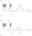
- Figures 2a to 2c shows schematically how a monitoring module according to the invention can be integrated into a line of a spray device.
- Fig. 2a shows the spray device.
- the spray device comprises a first container (22) containing a first liquid and a second container (23) containing a second liquid.
- the second liquid can be, for example, an active ingredient concentrate, wherein the active ingredient can be a pesticide.
- the first liquid can be a diluent for the active ingredient concentrate, for example, water.
- the first liquid is conveyed from the first container (22) towards at least one nozzle (27) via a first conveying means (24), such as an electrically driven pump.
- the second liquid is conveyed from the second container (23) towards at least one nozzle (27) via a second conveying means (25), such as an electrically driven pump.
- the liquids mix on their way through the line (28).
- a mixture of the first and second liquids emerges from the at least one nozzle (27).
- the flow can be stopped using a shut-off valve (26).
- Fig. 2a It is schematically shown that the line (28) between the containers (22, 23) and the at least one nozzle (27) is severed at one point (indicated by the scissors).
- Fig. 2b It is shown that the line (28) between the containers (22, 23) and the at least one nozzle (27) has been severed.
- the fluid connection between the containers (22, 23) and the at least one nozzle (27) is interrupted.
- the monitoring module (10) according to the invention is integrated at the point of interruption.
- the monitoring module (10) has a first connecting element (11) and a second connecting element (12).
- the first connecting element (11) is connected to the part of the line (28) that leads upstream in the direction of the containers (22, 23).
- the second connecting element (12) is connected to the part of the line (28) that leads downstream in the direction of the at least one nozzle (27).
- Fig. 2c shows the monitoring module (10) integrated into the line (28).
- the monitoring module (10) restores the fluid connection between the containers (22, 23) and the at least one nozzle (27). Liquid flowing from the containers (22, 23) toward the at least one nozzle (27) flows through a flow chamber (13) of the monitoring module.
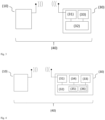
- Fig. 3 schematically shows an embodiment of a system according to the invention.
- the system (40) comprises a monitoring module (10) and a computer system (30).
- the monitoring module (10) can, for example, be the Fig. 1 shown monitoring module.
- the monitoring module is configured to transmit data on the amount of a spray medium flowing through a flow chamber of the monitoring module per unit of time to the computer system (30).
- the computer system (30) comprises a receiving unit (31), a control unit (32), and an output unit (33).
- the control unit (32) is configured to cause the receiving unit (31) to receive the data transmitted from the monitoring module (10).
- the control unit (32) is further configured to cause the output unit (33) to display the data to a user.
- Fig. 4 schematically shows a further embodiment of the system according to the invention.
- the system (40) comprises a monitoring module (10) and a computer system (30).
- the monitoring module (10) is configured to measure quantities of spray medium flowing per unit of time through a flow chamber (not explicitly shown) of the monitoring module (10) and to transmit data on these quantities to the computer system (30) via a transmitting unit (not explicitly shown) of the monitoring module.
- the computer system (30) comprises a receiving unit (31), a control unit (32), a quantity determination unit (36), a route tracking unit (35) with a GPS sensor (34), and an output unit (33).
- the quantity determination unit (36) and the route tracking unit (35) can be components of the control unit (32).
- the control unit (30) is configured to cause the receiving unit (31) to receive the data on the amounts of spray flowing through the flow chamber per unit time from the monitoring module (10).
- the control unit (32) is further configured to cause the route tracking unit (35) to track the route along which the computer system (30) (or the GPS sensor (34) as a component of the computer system (40)) is moved.
- the control unit (32) is further configured to
- the quantity determination unit (36) is configured to determine, based on the data transmitted by the monitoring module (10), the quantities of spraying agent that are applied per unit of time along the route with the spraying device.
- the control unit (32) is further configured to cause the output unit (33) to display information about the route and the quantities of spraying agent that are or have been applied along the route to a user.
- Figures 5 to 8 show screenshots of a mobile computer system to support a spraying process and to control, track and document the spraying process.
- Fig. 5 shows the successful completion of a calibration procedure supported by a computer program on the mobile computer system.
- the determined values can be displayed to the user as shown.
- the data is stored in the system and is used later to monitor compliance with the spray parameters.
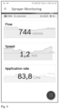
- Fig. 6 shows displays of the computer program during a spraying process. Above, the average amount of spray agent flowing through the flow chamber per unit time is shown as a function of time. The dashed line indicates the guideline value determined during calibration, which the user should adhere to in order to achieve an optimal spraying result. In the middle, the speed at which the user moves through the target area is shown as a function of time. The dashed line indicates the guideline speed at which the user should move in order to achieve an optimal spraying result. Below, the application rate per unit area is shown as a function of time. The dashed line indicates the guideline value that should be achieved in order to achieve an optimal spraying result.
- Fig. 7 shows a summary of variables after a spraying process. It shows how long the spraying process lasted ( Duration ) , what distance the user covered ( Distance ) , what area was sprayed ( Area ) , what the arithmetic mean flow rate was ( Flow ) , what volume of spray agent was sprayed ( Volume ) , what the arithmetic mean speed of the user was ( Speed ) and what the accuracy of the positioning was ( GPS accuracy ) .
- the data from a previously carried out calibration and parameters entered at the start of the spraying process e.g. area name, crop
- parameters entered at the start of the spraying process e.g. area name, crop
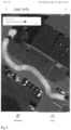
- Fig. 8 Displays the route traveled by a user on a map.
- the width of the strip indicates the spray width.
- the gray levels can indicate various parameters: the user's speed, the spray rate, the flow rate, and more.
- Fig. 9 shows a photograph of a monitoring module inserted into a line of a portable sprayer.
Landscapes
- Life Sciences & Earth Sciences (AREA)
- Engineering & Computer Science (AREA)
- Environmental Sciences (AREA)
- Zoology (AREA)
- Wood Science & Technology (AREA)
- Insects & Arthropods (AREA)
- Pest Control & Pesticides (AREA)
- Physics & Mathematics (AREA)
- Chemical & Material Sciences (AREA)
- Analytical Chemistry (AREA)
- Mechanical Engineering (AREA)
- Fluid Mechanics (AREA)
- Water Supply & Treatment (AREA)
- Soil Sciences (AREA)
- Electromagnetism (AREA)
- General Physics & Mathematics (AREA)
- Catching Or Destruction (AREA)
Applications Claiming Priority (4)
| Application Number | Priority Date | Filing Date | Title |
|---|---|---|---|
| EP19177562 | 2019-05-31 | ||
| EP19217003 | 2019-12-17 | ||
| PCT/EP2020/064382 WO2020239664A1 (fr) | 2019-05-31 | 2020-05-25 | Module de surveillance pour pulvérisateurs |
| EP20727299.8A EP3975713A1 (fr) | 2019-05-31 | 2020-05-25 | Module de surveillance pour pulvérisateurs |
Related Parent Applications (1)
| Application Number | Title | Priority Date | Filing Date |
|---|---|---|---|
| EP20727299.8A Division EP3975713A1 (fr) | 2019-05-31 | 2020-05-25 | Module de surveillance pour pulvérisateurs |
Publications (2)
| Publication Number | Publication Date |
|---|---|
| EP4541184A2 true EP4541184A2 (fr) | 2025-04-23 |
| EP4541184A3 EP4541184A3 (fr) | 2025-05-21 |
Family
ID=70779784
Family Applications (4)
| Application Number | Title | Priority Date | Filing Date |
|---|---|---|---|
| EP24213274.4A Pending EP4541184A3 (fr) | 2019-05-31 | 2020-05-25 | Module de surveillance pour pulvérisateurs |
| EP20727299.8A Ceased EP3975713A1 (fr) | 2019-05-31 | 2020-05-25 | Module de surveillance pour pulvérisateurs |
| EP24175381.3A Pending EP4410081A3 (fr) | 2019-05-31 | 2020-05-25 | Module de surveillance pour pulvérisateurs |
| EP24198238.8A Active EP4467937B1 (fr) | 2019-05-31 | 2020-05-25 | Module de surveillance pour pulvérisateurs |
Family Applications After (3)
| Application Number | Title | Priority Date | Filing Date |
|---|---|---|---|
| EP20727299.8A Ceased EP3975713A1 (fr) | 2019-05-31 | 2020-05-25 | Module de surveillance pour pulvérisateurs |
| EP24175381.3A Pending EP4410081A3 (fr) | 2019-05-31 | 2020-05-25 | Module de surveillance pour pulvérisateurs |
| EP24198238.8A Active EP4467937B1 (fr) | 2019-05-31 | 2020-05-25 | Module de surveillance pour pulvérisateurs |
Country Status (5)
| Country | Link |
|---|---|
| US (2) | US12520835B2 (fr) |
| EP (4) | EP4541184A3 (fr) |
| CN (2) | CN113873881A (fr) |
| PL (1) | PL4467937T3 (fr) |
| WO (1) | WO2020239664A1 (fr) |
Families Citing this family (5)
| Publication number | Priority date | Publication date | Assignee | Title |
|---|---|---|---|---|
| EP4541184A3 (fr) * | 2019-05-31 | 2025-05-21 | Bayer Aktiengesellschaft | Module de surveillance pour pulvérisateurs |
| DE102020110867A1 (de) * | 2020-04-22 | 2021-10-28 | Aesculap Ag | Intelligenter Ölsprayadapter |
| GB2614258B (en) * | 2021-12-22 | 2024-10-16 | Scarab Solutions Ltd | Monitoring apparatus and method for monitoring operation of fluid dispensing system |
| US11921493B2 (en) * | 2022-05-13 | 2024-03-05 | AgZen Inc. | Systems and methods for real-time measurement and control of sprayed liquid coverage on plant surfaces |
| PL441339A1 (pl) * | 2022-06-01 | 2023-12-04 | Suchar Tools Spółka Z Ograniczoną Odpowiedzialnością | Sposób i układ do nanoszenia powłok |
Citations (23)
| Publication number | Priority date | Publication date | Assignee | Title |
|---|---|---|---|---|
| DE2523338A1 (fr) | 1975-05-27 | 1976-09-02 | ||
| SE7611659L (sv) | 1975-10-23 | 1977-04-24 | Voss Armaturen | Slang- och/eller rorkoppling |
| DE3218965A1 (de) | 1982-05-19 | 1983-11-24 | Karl Dipl.-Ing.(FH) 4040 Neuss Weinhold | Vorrichtung zum verbinden von schlauch- oder rohrenden |
| EP0143588A2 (fr) | 1983-11-18 | 1985-06-05 | Brian Montandon | Pulvérisateur |
| DE3617199A1 (de) | 1986-05-22 | 1987-11-26 | Weinhold Karl | Vorrichtung zum verbinden eines schlauchendes mit einem anschlussstutzen |
| EP0256744A1 (fr) | 1986-08-07 | 1988-02-24 | Nomix-Chipman Limited | Dispositif pour qu'un piéton respecte une vitesse désirée |
| US4790454A (en) | 1987-07-17 | 1988-12-13 | S. C. Johnson & Son, Inc. | Self-contained apparatus for admixing a plurality of liquids |
| DE4139742A1 (de) | 1991-12-03 | 1993-06-09 | Karl Dipl.-Ing. Weinhold (Fh), 4040 Neuss, De | Schlauchkupplung |
| DE4211498A1 (de) | 1992-04-06 | 1993-10-07 | Em Technik Gmbh Armaturenbau | Rohrverschraubung für relativ starre Schläuche |
| DE9319397U1 (de) | 1993-12-17 | 1994-03-17 | Industrie-Technik Hubert Kienzler Inh. Hubert Kienzler, 79235 Vogtsburg | Kupplung für Mörtelschläuche |
| DE19818085A1 (de) | 1998-04-23 | 1999-10-28 | Hartmut Schmitz | Verfahren zur Herstellung einer Verbindung eines Schlauches, insbesondere eines Druckschlauches mit einer Armatur, sowie nach dem Verfahren hergestellte Schlauchverbindung |
| US20050006400A1 (en) | 2003-07-11 | 2005-01-13 | Shapanus Christopher J. | Portable fluid dispenser and method |
| US20050121462A1 (en) | 2003-11-21 | 2005-06-09 | Allen Leigh B.Iv | Backpack with sprayer |
| US20060102245A1 (en) | 2004-11-17 | 2006-05-18 | Kaechle Ronald W | Pumpless pressure sprayer |
| US20060249223A1 (en) | 2005-05-05 | 2006-11-09 | Leer Rick L | Tank sprayer with integrated measuring device |
| US20060261181A1 (en) | 2005-03-24 | 2006-11-23 | Pedro Wirz | Backpack sprayer |
| WO2013165684A2 (fr) | 2012-05-01 | 2013-11-07 | Central Garden & Pet Company | Système de pulvérisateur à cartouche |
| DE102013109785A1 (de) | 2013-09-06 | 2015-03-12 | Koubachi AG | Tragbare Sprühgerätvorrichtung |
| WO2015087805A1 (fr) | 2013-12-11 | 2015-06-18 | 本田技研工業株式会社 | Pulvérisateur dorsal à moteur |
| WO2018011012A1 (fr) | 2016-07-11 | 2018-01-18 | Bayer Cropscience Aktiengesellschaft | Pulvérisateur à cartouche échangeable |
| WO2018108696A1 (fr) | 2016-12-13 | 2018-06-21 | Bayer Cropscience Aktiengesellschaft | Pulvérisateur |
| DE102017000008A1 (de) | 2017-01-02 | 2018-07-05 | Fresenius Medical Care Deutschland Gmbh | Verfahren und Vorrichtung zum Aufstecken eines Schlauches auf eine formstabile Tülle |
| DE102017004353A1 (de) | 2017-05-08 | 2018-11-08 | Xenios Ag | Fixierring und Anordnung aus einem Schlauch und einem Fixierring |
Family Cites Families (28)
| Publication number | Priority date | Publication date | Assignee | Title |
|---|---|---|---|---|
| DE3417924C2 (de) | 1984-05-15 | 1986-10-02 | Karl Dipl.-Ing.(FH) 4040 Neuss Weinhold | Vorrichtung zum Verbinden eines Schlauchendes mit einem Anschlußstutzen |
| DE3916465A1 (de) * | 1989-05-20 | 1990-11-22 | Bayer Ag | Herstellung kugelfoermiger dispersionen durch kristallisation von emulsionen |
| JP2732491B2 (ja) * | 1994-07-11 | 1998-03-30 | ニューデルタ工業 株式会社 | 背負式動力噴霧機の散布速度表示装置 |
| DE102005013662A1 (de) * | 2005-03-16 | 2006-09-21 | Lechler Gmbh | Durchflussmengenmesser für Flüssigkeiten |
| US9532563B2 (en) * | 2011-08-12 | 2017-01-03 | Spraying Systems Co. | Spraying apparatus with spray nozzle flow sensing and monitoring system |
| WO2013030071A1 (fr) * | 2011-08-26 | 2013-03-07 | Basf Se | Procédé pour expulser un produit phytosanitaire et pistolet pulvérisateur |
| WO2013139407A1 (fr) * | 2012-03-21 | 2013-09-26 | Husqvarna Ab | Appareil d'arrosage comprenant un dispositif de mesure du débit |
| MX344075B (es) * | 2012-12-03 | 2016-12-05 | Wirz Luchsinger Pedro | Aspersora manual para prevención de fuga de líquidos. |
| US9788536B1 (en) * | 2014-01-30 | 2017-10-17 | The United States Of America, As Represented By The Secretary Of The Interior | Handheld data-logging spray apparatus |
| US20160044862A1 (en) * | 2014-08-14 | 2016-02-18 | Raven Industries, Inc. | Site specific product application device and method |
| CN110624717A (zh) * | 2015-06-01 | 2019-12-31 | 深圳市大疆创新科技有限公司 | 具有液体流量和转速的反馈的喷洒系统 |
| US10441965B2 (en) * | 2015-06-22 | 2019-10-15 | Deere & Company | Spray pattern of nozzle systems |
| EP3348329A1 (fr) * | 2017-01-16 | 2018-07-18 | Bayer CropScience Aktiengesellschaft | Appareil de pulvérisation |
| US20190388923A1 (en) * | 2017-01-27 | 2019-12-26 | Briggs & Stratton Corporation | Battery powered pressure washer |
| FR3064332A1 (fr) * | 2017-03-21 | 2018-09-28 | Le Savoir Industriel | Electrovanne pour surveiller et commander l’alimentation en fluide d’une installation d’un batiment, et dispositif comportant en outre une telle electrovanne |
| CN206882003U (zh) * | 2017-05-27 | 2018-01-16 | 深圳市沁丰智能科技有限公司 | 精准配药、多功能喷雾器 |
| US20180348030A1 (en) * | 2017-06-01 | 2018-12-06 | Kita Sensor Tech. Co., Ltd. | Sensor with a gas flow sensing chip for measurement of flow rate of a gas flowing through a gas conduit |
| US10252285B2 (en) * | 2017-08-08 | 2019-04-09 | Deere & Company | Mobile drift sensor for agricultural spraying |
| DE102017119972A1 (de) * | 2017-08-31 | 2019-02-28 | Amazonen-Werke H. Dreyer Gmbh & Co. Kg | Verfahren zum Ausbringen einer Spritzbrühe, computergestütztes Assistenzsystem und Spritzvorrichtung |
| US11103886B2 (en) * | 2018-01-15 | 2021-08-31 | Briggs & Stratton, Llc | Sprayer equipment with fluid mixing system |
| US20200001313A1 (en) * | 2018-06-29 | 2020-01-02 | Briggs & Stratton Corporation | Pressure washer with electronic governor |
| US20210386050A1 (en) * | 2018-10-02 | 2021-12-16 | Goizper, S.Coop. | Device for controlling the application of insecticides for indoor residual spraying using a sprayer and method of applying insecticides for indoor residual spraying by the use thereof |
| US11029180B2 (en) * | 2018-10-16 | 2021-06-08 | Corey CRAIG | Fluid metering component and spraying apparatuses thereof |
| US11925949B1 (en) * | 2018-10-16 | 2024-03-12 | Optix Technologies, LLC | Fluid metering component and spraying apparatus thereof |
| EP4541184A3 (fr) * | 2019-05-31 | 2025-05-21 | Bayer Aktiengesellschaft | Module de surveillance pour pulvérisateurs |
| CA3154863A1 (fr) * | 2019-10-04 | 2021-04-08 | Intelligent Agricultural Solutions Llc | Detection de parametres pour un applicateur de liquide |
| EP3939705A1 (fr) * | 2020-07-14 | 2022-01-19 | Andreas Stihl AG & Co. KG | Appareil de nettoyage haute pression |
| US11964291B2 (en) * | 2020-08-11 | 2024-04-23 | Graco Minnesota Inc. | Power control for a fluid sprayer with battery power |
-
2020
- 2020-05-25 EP EP24213274.4A patent/EP4541184A3/fr active Pending
- 2020-05-25 PL PL24198238.8T patent/PL4467937T3/pl unknown
- 2020-05-25 EP EP20727299.8A patent/EP3975713A1/fr not_active Ceased
- 2020-05-25 US US17/615,549 patent/US12520835B2/en active Active
- 2020-05-25 CN CN202080038926.3A patent/CN113873881A/zh active Pending
- 2020-05-25 CN CN202410403514.5A patent/CN118140900A/zh active Pending
- 2020-05-25 WO PCT/EP2020/064382 patent/WO2020239664A1/fr not_active Ceased
- 2020-05-25 EP EP24175381.3A patent/EP4410081A3/fr active Pending
- 2020-05-25 EP EP24198238.8A patent/EP4467937B1/fr active Active
-
2025
- 2025-10-03 US US19/349,496 patent/US20260026492A1/en active Pending
Patent Citations (26)
| Publication number | Priority date | Publication date | Assignee | Title |
|---|---|---|---|---|
| DE2523338A1 (fr) | 1975-05-27 | 1976-09-02 | ||
| SE7611659L (sv) | 1975-10-23 | 1977-04-24 | Voss Armaturen | Slang- och/eller rorkoppling |
| DE3218965A1 (de) | 1982-05-19 | 1983-11-24 | Karl Dipl.-Ing.(FH) 4040 Neuss Weinhold | Vorrichtung zum verbinden von schlauch- oder rohrenden |
| EP0143588A2 (fr) | 1983-11-18 | 1985-06-05 | Brian Montandon | Pulvérisateur |
| DE3617199A1 (de) | 1986-05-22 | 1987-11-26 | Weinhold Karl | Vorrichtung zum verbinden eines schlauchendes mit einem anschlussstutzen |
| EP0256744A1 (fr) | 1986-08-07 | 1988-02-24 | Nomix-Chipman Limited | Dispositif pour qu'un piéton respecte une vitesse désirée |
| US4790454A (en) | 1987-07-17 | 1988-12-13 | S. C. Johnson & Son, Inc. | Self-contained apparatus for admixing a plurality of liquids |
| DE4139742A1 (de) | 1991-12-03 | 1993-06-09 | Karl Dipl.-Ing. Weinhold (Fh), 4040 Neuss, De | Schlauchkupplung |
| DE4211498A1 (de) | 1992-04-06 | 1993-10-07 | Em Technik Gmbh Armaturenbau | Rohrverschraubung für relativ starre Schläuche |
| DE9319397U1 (de) | 1993-12-17 | 1994-03-17 | Industrie-Technik Hubert Kienzler Inh. Hubert Kienzler, 79235 Vogtsburg | Kupplung für Mörtelschläuche |
| DE19818085A1 (de) | 1998-04-23 | 1999-10-28 | Hartmut Schmitz | Verfahren zur Herstellung einer Verbindung eines Schlauches, insbesondere eines Druckschlauches mit einer Armatur, sowie nach dem Verfahren hergestellte Schlauchverbindung |
| US20050006400A1 (en) | 2003-07-11 | 2005-01-13 | Shapanus Christopher J. | Portable fluid dispenser and method |
| US20050121462A1 (en) | 2003-11-21 | 2005-06-09 | Allen Leigh B.Iv | Backpack with sprayer |
| US20060102245A1 (en) | 2004-11-17 | 2006-05-18 | Kaechle Ronald W | Pumpless pressure sprayer |
| US20060261181A1 (en) | 2005-03-24 | 2006-11-23 | Pedro Wirz | Backpack sprayer |
| US20060249223A1 (en) | 2005-05-05 | 2006-11-09 | Leer Rick L | Tank sprayer with integrated measuring device |
| WO2013165684A2 (fr) | 2012-05-01 | 2013-11-07 | Central Garden & Pet Company | Système de pulvérisateur à cartouche |
| DE102013109785A1 (de) | 2013-09-06 | 2015-03-12 | Koubachi AG | Tragbare Sprühgerätvorrichtung |
| WO2015087805A1 (fr) | 2013-12-11 | 2015-06-18 | 本田技研工業株式会社 | Pulvérisateur dorsal à moteur |
| WO2018011012A1 (fr) | 2016-07-11 | 2018-01-18 | Bayer Cropscience Aktiengesellschaft | Pulvérisateur à cartouche échangeable |
| WO2018011010A1 (fr) | 2016-07-11 | 2018-01-18 | Bayer Cropscience Aktiengesellschaft | Système de pulvérisation intelligent |
| WO2018011009A1 (fr) | 2016-07-11 | 2018-01-18 | Bayer Cropscience Aktiengesellschaft | Appareil de pulvérisation à mesure du débit |
| WO2018011011A1 (fr) | 2016-07-11 | 2018-01-18 | Bayer Cropscience Aktiengesellschaft | Appareil de pulvérisation comprenant des réservoirs de produit à pulvériser qui ne sont pas sous pression |
| WO2018108696A1 (fr) | 2016-12-13 | 2018-06-21 | Bayer Cropscience Aktiengesellschaft | Pulvérisateur |
| DE102017000008A1 (de) | 2017-01-02 | 2018-07-05 | Fresenius Medical Care Deutschland Gmbh | Verfahren und Vorrichtung zum Aufstecken eines Schlauches auf eine formstabile Tülle |
| DE102017004353A1 (de) | 2017-05-08 | 2018-11-08 | Xenios Ag | Fixierring und Anordnung aus einem Schlauch und einem Fixierring |
Non-Patent Citations (1)
| Title |
|---|
| K.W. BONFIG: "Technische Durchflussmessung", 2002, VULKAN-VERLAG |
Also Published As
| Publication number | Publication date |
|---|---|
| EP4467937C0 (fr) | 2025-12-31 |
| CN118140900A (zh) | 2024-06-07 |
| CN113873881A (zh) | 2021-12-31 |
| EP4410081A2 (fr) | 2024-08-07 |
| EP4467937A2 (fr) | 2024-11-27 |
| EP4410081A3 (fr) | 2024-09-25 |
| PL4467937T3 (pl) | 2026-04-20 |
| US20260026492A1 (en) | 2026-01-29 |
| WO2020239664A1 (fr) | 2020-12-03 |
| US20220232815A1 (en) | 2022-07-28 |
| EP3975713A1 (fr) | 2022-04-06 |
| US12520835B2 (en) | 2026-01-13 |
| EP4541184A3 (fr) | 2025-05-21 |
| EP4467937B1 (fr) | 2025-12-31 |
| EP4467937A3 (fr) | 2025-03-05 |
Similar Documents
| Publication | Publication Date | Title |
|---|---|---|
| EP4467937B1 (fr) | Module de surveillance pour pulvérisateurs | |
| CN112099556B (zh) | 农业无人飞行器的控制方法、地面控制端及存储介质 | |
| EP3481187B1 (fr) | Système de pulvérisation avec mesure de débit | |
| EP3554717B1 (fr) | Appareil de pulvérisation | |
| WO2022043511A1 (fr) | Surveillance d'application de pulvérisation spécifique à une buse | |
| EP3706567A1 (fr) | Procédé pour surveiller et/ou commander un processus d'approvisionnement d'un ensemble buse de pulvérisation en liquide de pulvérisation | |
| KR101391359B1 (ko) | 지리정보시스템을 이용한 무인항공 방제 시스템 및 그 제어방법 | |
| DE102017220006A1 (de) | Verfahren zum Überwachen und/oder Ändern einer Wirkmittelkonzentration in einer Spritzflüssigkeit einer Spritzvorrichtung | |
| DE102017220034A1 (de) | Verfahren zur sequenziellen Steuerung von Spritzdüseneinheiten | |
| DE102006016396A1 (de) | Mobile Referenzstation zur Erzeugung von Korrektursignalen für eine differentielle Positionsbestimmungseinrichtung | |
| CN108536170B (zh) | 一种航空变量施药监控装置及方法 | |
| DE102013109785A1 (de) | Tragbare Sprühgerätvorrichtung | |
| AT413175B (de) | Abdrift-informationssystem | |
| EP3706564A1 (fr) | Procédé relatif à un dispositif de pulvérisation | |
| EP3348329A1 (fr) | Appareil de pulvérisation | |
| EP3706565A1 (fr) | Procédé relatif à un dispositif de pulvérisation | |
| US12477968B2 (en) | Machine control system and method with roll-up reporting | |
| DE19704374A1 (de) | Verfahren und Vorrichtung zur Steuerung oder Regelung der Zuteil-, Dosier- sowie Ausbringeinrichtungen einer Ausbringmaschine | |
| DE102019107361B4 (de) | Verfahren zum Betreiben einer Pflanzen-Applikationsvorrichtung und eine Pflanzen-Applikationsvorrichtung | |
| ES3061065T3 (en) | Monitoring module for spray devices | |
| US20250344688A1 (en) | Spraying and Scouting Systems and Related Methods | |
| RU2617163C1 (ru) | Комплекс летательных аппаратов для внесения жидких средств химизации в точном земледелии | |
| US20220174863A1 (en) | Work map provision server | |
| Yallappa | Development and Evaluation of Drone Mounted Sprayer for Selected Field Crops | |
| EP3335553A1 (fr) | Appareil de pulvérisation |
Legal Events
| Date | Code | Title | Description |
|---|---|---|---|
| PUAI | Public reference made under article 153(3) epc to a published international application that has entered the european phase |
Free format text: ORIGINAL CODE: 0009012 |
|
| STAA | Information on the status of an ep patent application or granted ep patent |
Free format text: STATUS: THE APPLICATION HAS BEEN PUBLISHED |
|
| PUAL | Search report despatched |
Free format text: ORIGINAL CODE: 0009013 |
|
| AC | Divisional application: reference to earlier application |
Ref document number: 3975713 Country of ref document: EP Kind code of ref document: P |
|
| AK | Designated contracting states |
Kind code of ref document: A2 Designated state(s): AL AT BE BG CH CY CZ DE DK EE ES FI FR GB GR HR HU IE IS IT LI LT LU LV MC MK MT NL NO PL PT RO RS SE SI SK SM TR |
|
| AK | Designated contracting states |
Kind code of ref document: A3 Designated state(s): AL AT BE BG CH CY CZ DE DK EE ES FI FR GB GR HR HU IE IS IT LI LT LU LV MC MK MT NL NO PL PT RO RS SE SI SK SM TR |
|
| RIC1 | Information provided on ipc code assigned before grant |
Ipc: B05B 7/32 20060101ALN20250415BHEP Ipc: B05B 7/24 20060101ALN20250415BHEP Ipc: G01F 1/115 20060101ALI20250415BHEP Ipc: B05B 12/00 20180101ALI20250415BHEP Ipc: A01B 79/00 20060101ALI20250415BHEP Ipc: A01M 7/00 20060101AFI20250415BHEP |
|
| STAA | Information on the status of an ep patent application or granted ep patent |
Free format text: STATUS: REQUEST FOR EXAMINATION WAS MADE |
|
| 17P | Request for examination filed |
Effective date: 20251121 |
|
| RAP1 | Party data changed (applicant data changed or rights of an application transferred) |
Owner name: DISCOVERY PURCHASER CORPORATION |