EP4541306A2 - Pince hémostatique avec mécanisme de pince rechargeable - Google Patents
Pince hémostatique avec mécanisme de pince rechargeable Download PDFInfo
- Publication number
- EP4541306A2 EP4541306A2 EP24213948.3A EP24213948A EP4541306A2 EP 4541306 A2 EP4541306 A2 EP 4541306A2 EP 24213948 A EP24213948 A EP 24213948A EP 4541306 A2 EP4541306 A2 EP 4541306A2
- Authority
- EP
- European Patent Office
- Prior art keywords
- clip
- clip arms
- control member
- tissue
- arms
- Prior art date
- Legal status (The legal status is an assumption and is not a legal conclusion. Google has not performed a legal analysis and makes no representation as to the accuracy of the status listed.)
- Pending
Links
Images


Classifications
-
- A—HUMAN NECESSITIES
- A61—MEDICAL OR VETERINARY SCIENCE; HYGIENE
- A61B—DIAGNOSIS; SURGERY; IDENTIFICATION
- A61B17/00—Surgical instruments, devices or methods
- A61B17/08—Wound clamps or clips, i.e. not or only partly penetrating the tissue ; Devices for bringing together the edges of a wound
- A61B17/083—Clips, e.g. resilient
-
- A—HUMAN NECESSITIES
- A61—MEDICAL OR VETERINARY SCIENCE; HYGIENE
- A61B—DIAGNOSIS; SURGERY; IDENTIFICATION
- A61B17/00—Surgical instruments, devices or methods
- A61B17/10—Surgical instruments, devices or methods for applying or removing wound clamps, e.g. containing only one clamp or staple; Wound clamp magazines
- A61B17/105—Wound clamp magazines
-
- A—HUMAN NECESSITIES
- A61—MEDICAL OR VETERINARY SCIENCE; HYGIENE
- A61B—DIAGNOSIS; SURGERY; IDENTIFICATION
- A61B17/00—Surgical instruments, devices or methods
- A61B17/12—Surgical instruments, devices or methods for ligaturing or otherwise compressing tubular parts of the body, e.g. blood vessels or umbilical cord
- A61B17/122—Clamps or clips, e.g. for the umbilical cord
- A61B17/1222—Packages or dispensers therefor
-
- A—HUMAN NECESSITIES
- A61—MEDICAL OR VETERINARY SCIENCE; HYGIENE
- A61B—DIAGNOSIS; SURGERY; IDENTIFICATION
- A61B17/00—Surgical instruments, devices or methods
- A61B17/12—Surgical instruments, devices or methods for ligaturing or otherwise compressing tubular parts of the body, e.g. blood vessels or umbilical cord
- A61B17/122—Clamps or clips, e.g. for the umbilical cord
- A61B17/1227—Spring clips
-
- A—HUMAN NECESSITIES
- A61—MEDICAL OR VETERINARY SCIENCE; HYGIENE
- A61B—DIAGNOSIS; SURGERY; IDENTIFICATION
- A61B17/00—Surgical instruments, devices or methods
- A61B17/12—Surgical instruments, devices or methods for ligaturing or otherwise compressing tubular parts of the body, e.g. blood vessels or umbilical cord
- A61B17/128—Surgical instruments, devices or methods for ligaturing or otherwise compressing tubular parts of the body, e.g. blood vessels or umbilical cord for applying or removing clamps or clips
- A61B17/1285—Surgical instruments, devices or methods for ligaturing or otherwise compressing tubular parts of the body, e.g. blood vessels or umbilical cord for applying or removing clamps or clips for minimally invasive surgery
-
- A—HUMAN NECESSITIES
- A61—MEDICAL OR VETERINARY SCIENCE; HYGIENE
- A61B—DIAGNOSIS; SURGERY; IDENTIFICATION
- A61B17/00—Surgical instruments, devices or methods
- A61B2017/00526—Methods of manufacturing
- A61B2017/0053—Loading magazines or sutures into applying tools
-
- A—HUMAN NECESSITIES
- A61—MEDICAL OR VETERINARY SCIENCE; HYGIENE
- A61B—DIAGNOSIS; SURGERY; IDENTIFICATION
- A61B17/00—Surgical instruments, devices or methods
- A61B2017/00743—Type of operation; Specification of treatment sites
- A61B2017/00778—Operations on blood vessels
-
- A—HUMAN NECESSITIES
- A61—MEDICAL OR VETERINARY SCIENCE; HYGIENE
- A61B—DIAGNOSIS; SURGERY; IDENTIFICATION
- A61B17/00—Surgical instruments, devices or methods
- A61B2017/00743—Type of operation; Specification of treatment sites
- A61B2017/00818—Treatment of the gastro-intestinal system
-
- A—HUMAN NECESSITIES
- A61—MEDICAL OR VETERINARY SCIENCE; HYGIENE
- A61B—DIAGNOSIS; SURGERY; IDENTIFICATION
- A61B90/00—Instruments, implements or accessories specially adapted for surgery or diagnosis and not covered by any of the groups A61B1/00 - A61B50/00, e.g. for luxation treatment or for protecting wound edges
- A61B90/03—Automatic limiting or abutting means, e.g. for safety
- A61B2090/033—Abutting means, stops, e.g. abutting on tissue or skin
- A61B2090/034—Abutting means, stops, e.g. abutting on tissue or skin abutting on parts of the device itself
Definitions
- GI gastrointestinal
- Hemostasis clips grasp tissue surrounding a wound and hold edges of the wound together temporarily to allow natural healing processes to permanently close the wound.
- Specialized endoscopic clipping devices are used to deliver the clips at the desired locations within the body after which the clip delivery device is withdrawn, leaving the clip within the body.
- the present disclosure relates to a system for treating tissue, comprising a clip assembly and an applicator.
- the clip assembly includes a pair of clip arms, a proximal end of the clip arms connected to a yoke, the clip assembly movable between a biased tissue receiving configuration, in which distal ends thereof are separated from one another to receive a target tissue therebetween, and a tissue gripping configuration, the clip arms including a locking mechanism for locking the clip arms in the tissue gripping configuration.
- the applicator includes a sleeve and a control member extending therethrough, the sleeve extending from a proximal end to a distal end and including a lumen extending therethrough, the control member extending from a proximal end to a distal end configured to be releasably coupled to the yoke to move the clip assembly between the tissue receiving configuration and the tissue gripping configuration, the clip arms being constrained toward the tissue gripping configuration via a surface of the lumen when the clip arms are drawn proximally thereinto.
- the locking mechanism may include corresponding mating features on each of the clip arms.
- a first one of the clip arms may include a male locking feature extending therefrom toward a second one of the clip arms and the second one of the clip arms includes a female locking feature.
- the male locking feature may be deformable to be received in the female locking feature.
- the female locking feature may be deformable to receive the male locking feature therein.
- the locking mechanism may include a pair of locking jaws extending from opposing longitudinal edges of a first one of the clip arms toward a second one of the clip arms, the pair of locking jaws including a gripping end that is configured to be snapped over the second one of the clip arms to lock the clip arms relative to one another.
- the yoke may include a longitudinal slot extending thereinto from a proximal opening to a distal space, the longitudinal slot defined via opposed portions that are deformable to permit an enlarged distal end of the control member to be moved distally past the proximal opening into the distal space.
- the yoke may be configured to be deformed when a force exerted thereon by the enlarged distal end exceeds a predetermined threshold value.
- the clip arms may be formed via a single piece of material bent to define the pair of arms.
- the system may further comprise a cartridge for housing the clip assembly, the cartridge including a groove formed therein to accommodate the clip assembly and an opening extending thereinto from an exterior of the cartridge in communication with the groove, the opening sized and shaped to receive a distal portion of the applicator.
- the applicator may include a flexible member extending proximally from the locking sleeve, a handle member connected to the proximal end of the flexible member, and an actuator coupled to the handle member for moving the clip assembly between the tissue receiving and tissue clipping configurations.
- the handle member may include a protrusion extending therefrom to interface with the actuator to provide tactile feedback to a user regarding a position of the distal end of the control member relative to the sleeve.
- the present disclosure also relates to a clip assembly, comprising a pair of clip arms and a yoke.
- the clip arms are movable between a biased tissue receiving configuration, in which distal ends thereof are separated from one another to receive a target tissue therebetween, and a tissue gripping configuration, in which the distal ends of the clip arms are drawn toward one another to grip the target tissue therebetween, the clip arms including a locking mechanism for locking the clip arms in the tissue gripping configuration.
- the yoke is connected to a proximal end of the clip arms, the yoke including a distal portion engaging the clip arms and a proximal portion configured to releasably engage a control member of an applicator, the proximal portion including opposed portions defining a slot extending from a proximal opening to a distal space sized and shaped to hold a distal end of the control member therein.
- a first one of the clip arms may include a male locking feature extending therefrom toward a second one of the clip arms and the second one of the clip arms includes a female locking feature, the male and female locking features engagable with one another to lock the clip arms relative to one another, one of the male and female locking features being deformable to engage the other one of the male and female locking features.
- the locking mechanism may include a pair of locking jaws extending from opposing longitudinal edges of a first one of the clip arms toward a second one of the clip arms, the pair of locking jaws including a gripping end that is configured to be snapped over the second one of the clip arms to lock the clip arms relative to one another.
- the present disclosure also relates to a method for treating tissue, comprising loading a first clip assembly on an applicator by coupling a control member of the applicator to a yoke at a proximal end of clip arms of the first clip assembly by pushing an enlarged distal end of the control member into a socket of the yoke, inserting the loaded clip assembly to a target site within a living body via a working channel of an endoscope, moving the first clip assembly between an open configuration, in which distal ends of the clip arms are separated from one another, and a closed configuration, in which the distal ends of the clip arms are drawn toward one another, by moving the control member longitudinally relative to the locking sleeve until a target tissue is gripped between the distal ends, as desired, the clip arms constrained toward the closed configuration via an interior surface of the sleeve when the clip arms are drawn proximally thereinto, locking the clip arms in the closed configuration by drawing the control member further proximally until the first and second clip arms engage one another
- the present disclosure relates to a clipping system and, in particular, relates to a reloadable endoscopic clipping system.
- Exemplary embodiments of the present disclosure describe a clip assembly that may be loaded onto a distal end of an applicator assembly prior to an endoscopic procedure. Once a clip has been deployed at a desired target area in the body, the applicator assembly may be reloaded with a new clip.
- the clip assembly includes a pair of arms, proximal ends of which are connected to a yoke that is configured to releasably engage a distal end of a control member of an applicator.
- Each of the clip arms include corresponding locking features so that, when it is desired to lock the clip arms in a tissue gripping configuration, the clip arms may be drawn toward one another until the corresponding locking features engage one another. Once the clip arms have been locked, a proximal force beyond a predetermined threshold value may be exerted on the control member, disengaging the control member from the yoke so that the control member may be coupled to a new clip assembly.
- proximal and distal are intended to refer to a direction toward (proximal) and away from (distal) a user of the device.
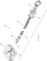
- a system 100 comprises a clip assembly 102, an applicator 104 and a cartridge 106.
- the clip assembly 102 is loadable into a distal portion of the applicator 104 prior to insertion of the system 100 into a living body for the clipping of target tissue.
- the applicator 104 is configured such that, after deployment of the clip assembly 102 in the living body, a new clip assembly 102 may be loaded onto the applicator 104 so that the same applicator 104 may be used to deliver a new clip assembly 102 to a second portion of target tissue in the living body.
- Each clip assembly 102 is stored in the cartridge 106, which facilitates loading of the clip assembly 102 onto the applicator 104.
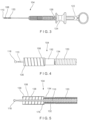
- the applicator 104 includes a sleeve 108 at a distal end thereof and a control member 110 extending therethrough.
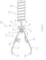
- the clip assembly 102 includes a pair of clip arms 112 including a proximal end 114 connected to a yoke 116 that is configured to releasably engage a distal end 118 of the control member 110.
- the clip assembly 102 may be moved between a tissue receiving configuration and a tissue gripping configuration by moving the clip arms 112 relative to the sleeve 108.
- the applicator 104 includes the sleeve 108, a flexible member 120 extending proximally therefrom, and the control member 110 extending through the sleeve 108 and the flexible member 120.
- a proximal end of the flexible member 120 is connected to a handle member 122, which includes an actuator such as, for example, a spool 124, coupled thereto.
- the spool 124 is connected to a proximal end 126 of the control member 110 so that, once the clip assembly 102 is loaded onto the applicator 104, the spool 124 may be slid longitudinally over the handle member 122 to move the clip assembly 102 between the tissue receiving and tissue gripping configurations.
- the handle member 122 includes a positioning feature 128 interfacing with the spool 124 to provide tactile feedback to a user of the system 100 regarding a position of the yoke 116 with respect to the sleeve 108.
- the positioning feature 128 includes a deformable protrusion extending laterally outward from an exterior surface therefrom. The protrusion is deformable so that the spool 124 may be slid thereover when a force exerted thereon exceeds a predetermined threshold value. As will be described in further detail below, the spool 124 may be slid thereover during initial loading of the clip assembly 102.
- the positioning feature 128 provides a tactile feedback to the user indicating that the yoke 116 is at a distal-most position with respect to the sleeve 108, without extending entirely distally past the sleeve 108.
- the clip assembly 102 is at a maximum open configuration without extending entirely out of the sleeve 108 (e.g., separated from the sleeve 108).
- the flexible member 120 may be formed as a coil of wire through which the control member 110 extends from the distal end 118 to the proximal end 126.
- the coil of wire preferably has sufficient flexibility to be passed through even tortuous paths of living body and, in this embodiment, is sized and shaped to permit it to be passed through a working channel of an endoscope or other insertion device.
- the flexible member 120 is shown and described as a coil of wire, it will be understood by those of skill in the art that any other suitable flexible structure may be employed so long as the flexible member 120 is capable of providing a force in compression sufficient to counter the tension to be placed on the control member 110 from the clip assembly 102.
- the applicator 104 is described as including the spool 124, the applicator 104 may include any of a variety of actuating mechanisms for moving the control member 110 to control movement of the clip arms 112.
- the control member 110 extends from the distal end 118 releasably coupleable to the yoke 116 to the proximal end 126 connected to the spool 124.
- the distal end 118 is sized and shaped to be releasably coupled to a corresponding feature of the yoke 116.
- the distal end 118 may be shaped as an enlarged ball that is received within a correspondingly shaped socket of the yoke 116. It will be understood by those of skill in the art, however, that the distal end 118 may have any of a variety of shapes and sizes so long as the distal end 118 is releasably coupleable with the yoke 116.
- the sleeve 108 extends longitudinally from a proximal end 132 connected to a distal end 134 of the flexible member 120 to a distal end 136 and including a lumen 138 extending therethrough.
- the lumen 138 may be sized and shaped to receive at least a portion of the clip assembly 102 therein.
- the lumen 138 includes a shoulder 176 along a proximal portion thereof which reduces a cross-sectional area of the lumen 138 proximally thereof so that, the yoke 116 is prevented from passing proximally past the shoulder 176.
- the sleeve 108 may be configured as a hypotube attached to the distal end 134 of the flexible member 120.
- the sleeve 108 may be laser cut to increase a flexibility thereof.
- the sleeve 108 may include a helically extending cut therealong so that the sleeve 108 may be flexed along a length thereof.
- the clip assembly 102 includes the pair of arms 112, proximal ends 114 of which are connected to the yoke 116.
- the pair of arms 112 is formed of a single piece of material 142 bent in half at a center point 146 to form the two arms 112.
- the yoke 116 may be connected to the single piece of material at the point at which the material bends (e.g., center point 146) to form the two arms 112.
- the material 142 includes an elongated slot 144 extending through the center point 146 along a length thereof.
- a locking rod 148 of the yoke 116 may be inserted through the elongated slot 144 so that the locking rod 148 is received between proximal ends 114 of the clip arms 112. Once inserted, the locking rod 148 may be rotated to lock the yoke 116 relative to the material 142 of the clip arms 112.
- the clip arms 112 are described and shown as being formed of the single piece of material 142, in another embodiment, the pair of arms 112 may be formed via two separate pieces of material, proximal ends of which are connected to one another via the yoke 116.
- the clip arms 112 of this embodiment are biased so that distal ends 140 thereof move apart from one another into an open tissue receiving configuration when not drawn into the sleeve 108.
- the sleeve 108 constrains the clip arms 112, holding the distal ends 140 thereof together in a closed tissue gripping configuration.
- the yoke 116 is longitudinally slidable with the lumen 138 of the sleeve 108 to move the clip arms 112 between the tissue receiving configuration and the tissue gripping configuration.
- the distal ends 140 of each of the clip arms 112 may project laterally inward toward the distal end 140 of the other of the clip arms 112 to facilitate gripping of target tissue therebetween.
- the distal ends 140 may further include other gripping features such as, for example, teeth and/or protrusions.
- the clip arms 112 include corresponding mating features 150, 152 for locking the clip arms 112 in the closed tissue gripping configuration.
- a first one of the arms 112 includes a male lock feature 150 while a second one of the arms 112 includes a female lock feature 150.
- the male lock feature 150 extends from the first one of the arms 112 toward the second one of the arms 112 and includes a pair of prongs 154 including locking tabs 155 extending laterally outward therefrom.
- the female mating feature 152 includes an opening 156 extending laterally through the second one of the arms 112. The opening 156 is sized and shaped to permit the pair of prongs 154 to be received therein.
- the pair of prongs 154 are deformable (i.e., movable toward one another) to permit the locking tabs 155 to be passed through the opening 156. Once the locking tabs 155 pass through the opening 156, the pair of prongs 154 revert to their original configuration, locking the male locking feature 150 within the opening 156.
- the locking tabs 155 may be configured to permit the locking tabs 155 through the opening 156 in one direction (i.e., toward the locked configuration) while being prevented from passing thereoutof in the opposite direction.
- surfaces of the locking tabs 154 facing away from the first one of the clip arms 112 are angled or curved while surfaces of the locking tabs 154 facing toward the first one of the clip arms 112 are substantially planar.
- planar surfaces of the locking tabs 154 engage the second one of the clip arms 112, locking the clip arms 112 relative to one another in tissue gripping configuration.
- the male and female lock features 150, 152 are specifically configured so that the male and female lock features 150, 152 engage one another only when the pair of clip arms 112 are drawn toward one another beyond a predetermined threshold distance.
- the pair of arms 112 may be moved between the tissue receiving and tissue gripping configurations multiple times, as desired, prior to locking of the clip assembly 102 in the tissue gripping configuration.
- the yoke 116 includes the locking rod 148 at a distal end thereof and a proximal portion 158 extending proximally therefrom to receive the distal end 118 of the control member 110 therein.
- the proximal portion 158 includes a longitudinal slot 160 defined via opposed portions 162 that are spreadable to receive the distal end 118 of the control member 110.
- the longitudinal slot 160 extends from a proximal opening 164 to a space 166 sized and shaped to receive the distal end 118.
- the distal end 118 may be configured as a ball received within a correspondingly sized and shaped socket of the space 166.
- the proximal opening 164 of the slot 160 has a smaller cross-sectional area (e.g., diameter) than a cross-sectional area of the space 166.
- the opposed portions 162 are spreadable to receive the distal end 118 of the control member 110 and biased toward one another so that, once the distal end 118 passes distally into the space 166, the opposed portions 162 of the proximal portion 158 spring back to lock the distal end 118 within the space 166, coupling the control member 110 to the yoke 116.
- longitudinal movement of the control member 110 relative to the sleeve 108 may control movement of the clip arms 112 between the tissue receiving and the tissue clipping configurations.
- the distal end 118 of the control member 110 may be inserted into the proximal portion 158 of the yoke 116 via the proximal opening 164.
- the proximal opening 164 of the longitudinal slot 160 deforms to permit the distal end 118 to be passed through the proximal opening 164 into the space 166.
- opposed portions 162 defining the longitudinal slot 160 may be separated from one another to permit the distal end 118 to be passed through the proximal opening 164 into the space 166. Once the distal end 118 is received within the space 166, the longitudinal slot 160 reverts to its original size, holding the distal end 118 of the control member 110 therein.
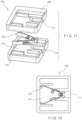
- the clip assembly 102 is stored in a cartridge 106, which may be configured, for example, as a storage container comprising a base 168 and a lid 170.
- the base 168 and the lid 170 include features for coupling the base 168 and the lid 170 to one another so that the clip assembly 102 may be securely stored therein.
- each of the base 168 and the lid 170 includes a groove 172 which, when the base 168 and the lid 170 are assembled with one another, forms a space for housing the clip assembly 102.
- the clip assembly 102 may be stored in the assembled cartridge 106 in the tissue receiving configuration.
- the assembled base and lid 168, 170 may include a proximal opening 174 through which a distal portion of the applicator 104 (e.g., the distal end 118 of the control member 110 and the distal end 136 of the sleeve 108) may be inserted into the cartridge 106 to load the clip assembly 102 thereon.
- a distal portion of the applicator 104 e.g., the distal end 118 of the control member 110 and the distal end 136 of the sleeve 108
- the clip assembly 102 may be drawn toward the tissue gripping configuration to remove the clip assembly 102 from the cartridge 106.
- An exemplary method for loading the clip assembly 102 housed within the cartridge 106 to the applicator 104 comprises inserting the control member 110 and/or the sleeve 108 of the applicator 104 through the proximal opening 174 of the cartridge 106.
- the distal end 118 of the control member 110 is moved with respect to the cartridge 106 by, for example, moving the spool 124 distally against the yoke 116 until a distal force of the distal end 118 against the yoke 116 exceeds a predetermined threshold value, deforming the proximal opening 164 of the slot 160 of the yoke 116 to permit the distal end 118 to pass therethrough into the space 166 of the yoke 116.
- the spool 124 may slide distally over the positioning feature 128 of the handle member 122, providing tactile feedback to the user that the distal end 118 of the control member 110 has been extended distally past the distal end 136 of the sleeve 108 to be coupled to the yoke 116.
- the yoke 116 reverts to its original shape, holding the distal end 118 therewithin.
- the clip assembly 102 Upon coupling of the yoke 116 and the control member 110, the clip assembly 102 has been successfully loaded onto the applicator 104.
- the clip arms 112 are drawn proximally with respect to the sleeve 108 of the applicator 104 to move the clip arms 112 toward the tissue gripping configuration.
- the spool 124 may be drawn proximally with respect to the handle member 122 until the spool 124 is drawn proximally of the positioning feature 128.
- an interior surface of the lumen 138 of the sleeve 108 constrains the clip arms 112 as they are drawn thereinto, to move the clip assembly 102 toward the tissue gripping configuration.
- the clip assembly 102 may then be drawn out of the cartridge 106 via the opening 174.
- the clip assembly 102 is inserted through a working channel of an endoscope (or any other insertion device) and inserted into the body (e.g., through a natural body lumen) to a site adjacent to a target portion of tissue to be clipped.
- the clip assembly 102 is inserted to the target tissue in the closed configuration to facilitate its passage through the working channel.
- the clip assembly 102 Upon reaching the site of the target tissue, the clip assembly 102 is advanced out of the distal end of the working channel and the clip arms 112 are extended out of the sleeve 108 of the applicator 104 to move the clip arms 112 toward the tissue receiving configuration by, for example, sliding the spool 124 distally over the handle member 122. Abutment of the distal surface 130 of the spool 124 with the positioning feature 128 provides tactile feedback to the user, indicating that the clip arms 112 are at the maximum open configuration, and that moving the spool 124 any further distally would result in the yoke 116 extending distally out of the sleeve 108.
- the clip arms 112 may be repeatedly moved between the tissue receiving and the tissue gripping configurations until a target portion of tissue is received between the distal ends 140 of the clip arms 112, as desired. Once the target portion of tissue is received between the arms 112, the clip assembly 102 is moved toward the tissue gripping configuration by moving the control member 110 proximally relative to the clip assembly 102. When it is confirmed that the desired portion of tissue is gripped between the clip arms 112 (e.g., portions of tissue on opposite sides of a bleeding wound), the control member 110 is drawn further proximally relative to the clip assembly 102 (via the spool 124) to lock the clip assembly 102 in the closed configuration.
- the desired portion of tissue is gripped between the clip arms 112 (e.g., portions of tissue on opposite sides of a bleeding wound)
- the control member 110 is drawn further proximally relative to the clip assembly 102 (via the spool 124) to lock the clip assembly 102 in the closed configuration.
- the clip arms 112 are drawn further proximally into the sleeve 1088 until the male and female locking features 150, 152 engage one another, locking the clip arms 112 relative to one another.
- the control member 110 is drawn proximally with respect to the locking sleeve 108 until the yoke 116 comes into contact with and abuts the shoulder 176 of the lumen 138 of the sleeve 108.
- the shoulder 176 prevents the yoke 116 from moving proximally therepast while a continued proximal force is exerted on the control member 110.
- the yoke 116 deforms (e.g., the proximal opening 164 expands) to permit the distal end 118 to be released from the longitudinal slot 160.
- the applicator 104 may be withdrawn from the living body, leaving the clip assembly 102 in the body over the target tissue. If so desired, a new clip assembly 102 is then loaded onto the applicator 104, in the same manner as described above, so that the device may then be used to clip a second portion of tissue. This process may be repeated using the same applicator 104 as many times as needed or desired.
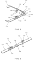
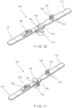
- a clip assembly 202 may be substantially similar to the clip assembly 102, comprising a pair of clip arms 212 connected to a yoke 216 at a proximal end thereof.
- the clip assembly 202 may be used with the applicator 104 in a manner substantially similar to the system 100 described above.
- the clip assembly 202 comprises a male locking feature 250 and a corresponding female locking feature 252 for locking the clip arms 212 relative to one another.
- the opening 256 is lined with a deformable material 257 that deforms to permit a locking tab 254 of the male locking feature 250 to be passed therethrough.
- the deformable material 257 of the opening 256 reverts to its original shape, holding the male locking feature 250 therein.
- the locking tab 254 is shaped to permit the locking tab 254 to be passed through the opening 256 in one direction (i.e., toward the locked configuration) while preventing the locking tab 254 from being passed therethrough in the opposite direction.
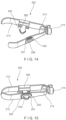
- a clip assembly 302 may be substantially similar to the clip assemblies 102, 202 described above.
- the clip assembly 302 may be utilized with the applicator 104 in a manner substantially similar to the system 100 described above.
- the clip assembly 302 similarly comprises a pair of clip arms 312 connected to a yoke 316 at a proximal end 314 thereof.
- a first one of the clip arms 312 includes a pair of locking jaws 350 extending therefrom.
- Each of the locking jaws 350 extends laterally from a longitudinal edge 378 of the first one of the arms 312 toward a second one of the arms 312.
- Each of the locking jaws 350 extends from opposing longitudinal edges 378.
- the jaws 350 extend from the first one of the clip arms 312 toward gripping ends 352 which extend inward toward one another so that, when the clip arms 312 are drawn toward one another to a locked configuration, the gripping ends 352 snap over opposing sides of the second one of the clip arms 312 to grip the second clip arms 312 and lock the clip arms 312 relative to one another.
- the gripping ends 352 are shaped to permit the clip arms 312 from being moved toward one another to the locked configuration, while preventing the gripping ends 352 from disengaging the second one of the clip arms 312 upon locking.
- a first surface 354 of the gripping ends 352 facing away from the first one of the clip arms 312 may be curved while a second surface 356 facing toward the first one of the clip arms 312 is substantially planar.
- clip assemblies 102, 202, 302 are described as including specific locking features, it will be understood by those of skill in the art that a clip assembly of the present disclosure may include any of a variety of corresponding mating features for locking the clip arms relative to one another.
Landscapes
- Health & Medical Sciences (AREA)
- Surgery (AREA)
- Life Sciences & Earth Sciences (AREA)
- Heart & Thoracic Surgery (AREA)
- Nuclear Medicine, Radiotherapy & Molecular Imaging (AREA)
- Engineering & Computer Science (AREA)
- Biomedical Technology (AREA)
- Medical Informatics (AREA)
- Molecular Biology (AREA)
- Animal Behavior & Ethology (AREA)
- General Health & Medical Sciences (AREA)
- Public Health (AREA)
- Veterinary Medicine (AREA)
- Vascular Medicine (AREA)
- Reproductive Health (AREA)
- Surgical Instruments (AREA)
Applications Claiming Priority (3)
| Application Number | Priority Date | Filing Date | Title |
|---|---|---|---|
| US201662398284P | 2016-09-22 | 2016-09-22 | |
| PCT/US2017/051381 WO2018057370A1 (fr) | 2016-09-22 | 2017-09-13 | Clip d'hémostase avec mécanisme de clippage rechargeable |
| EP17784059.2A EP3484378B1 (fr) | 2016-09-22 | 2017-09-13 | Clip d'hémostase avec mécanisme de clippage rechargeable |
Related Parent Applications (1)
| Application Number | Title | Priority Date | Filing Date |
|---|---|---|---|
| EP17784059.2A Division EP3484378B1 (fr) | 2016-09-22 | 2017-09-13 | Clip d'hémostase avec mécanisme de clippage rechargeable |
Publications (2)
| Publication Number | Publication Date |
|---|---|
| EP4541306A2 true EP4541306A2 (fr) | 2025-04-23 |
| EP4541306A3 EP4541306A3 (fr) | 2025-07-16 |
Family
ID=60083412
Family Applications (2)
| Application Number | Title | Priority Date | Filing Date |
|---|---|---|---|
| EP17784059.2A Active EP3484378B1 (fr) | 2016-09-22 | 2017-09-13 | Clip d'hémostase avec mécanisme de clippage rechargeable |
| EP24213948.3A Pending EP4541306A3 (fr) | 2016-09-22 | 2017-09-13 | Pince hémostatique avec mécanisme de pince rechargeable |
Family Applications Before (1)
| Application Number | Title | Priority Date | Filing Date |
|---|---|---|---|
| EP17784059.2A Active EP3484378B1 (fr) | 2016-09-22 | 2017-09-13 | Clip d'hémostase avec mécanisme de clippage rechargeable |
Country Status (7)
| Country | Link |
|---|---|
| US (1) | US10820903B2 (fr) |
| EP (2) | EP3484378B1 (fr) |
| JP (1) | JP6865270B2 (fr) |
| CN (1) | CN109788958A (fr) |
| AU (1) | AU2017330257B2 (fr) |
| CA (1) | CA3030999C (fr) |
| WO (1) | WO2018057370A1 (fr) |
Families Citing this family (27)
| Publication number | Priority date | Publication date | Assignee | Title |
|---|---|---|---|---|
| WO2020136826A1 (fr) * | 2018-12-27 | 2020-07-02 | オリンパス株式会社 | Dispositif médical et procédé d'installation de dispositif médical |
| CN112190299B (zh) * | 2019-07-08 | 2025-07-29 | 江苏风和医疗器材股份有限公司 | 组织夹 |
| JP7241917B2 (ja) * | 2019-07-16 | 2023-03-17 | ボストン サイエンティフィック サイムド,インコーポレイテッド | 再装填可能な止血デバイス用クリップの圧着取付け |
| KR102755550B1 (ko) * | 2019-11-05 | 2025-01-21 | 보스톤 싸이엔티픽 싸이메드 인코포레이티드 | 조직 포획 나선형 디바이스 |
| USD1028240S1 (en) * | 2019-11-19 | 2024-05-21 | Pointsource Technologies, Llc | Radioactive therapeutic device |
| CN111421752B (zh) * | 2020-04-20 | 2025-03-25 | 江苏造裕智能装备有限公司 | 管件埋入取出治具 |
| CN111544075B (zh) * | 2020-06-12 | 2024-10-01 | 南微医学科技股份有限公司 | 一种新型止血夹 |
| WO2022047782A1 (fr) * | 2020-09-07 | 2022-03-10 | 江苏风和医疗器材股份有限公司 | Pince à tissu |
| CN114145804B (zh) * | 2020-09-07 | 2024-01-16 | 江苏风和医疗器材股份有限公司 | 组织夹 |
| JP7668359B2 (ja) * | 2020-12-16 | 2025-04-24 | ボストン サイエンティフィック サイムド,インコーポレイテッド | 筋肉レベルにおける組織を把持するためのデバイスおよびシステム |
| US12150630B2 (en) * | 2021-01-06 | 2024-11-26 | Covidien Lp | Wire gripping device |
| WO2022173024A1 (fr) * | 2021-02-12 | 2022-08-18 | Olympus Medical Systems Corp. | Dispositif d'attache et procédé de fonctionnement de dispositif d'attache |
| JP7389155B2 (ja) | 2021-02-12 | 2023-11-29 | オリンパスメディカルシステムズ株式会社 | クリップ装置 |
| CN113081143B (zh) * | 2021-05-25 | 2022-05-31 | 广州科慧健远医疗科技有限公司 | 一种组织夹持装置 |
| CN117940077A (zh) * | 2021-09-18 | 2024-04-26 | 杭州安杰思医学科技股份有限公司 | 夹子器械 |
| WO2023051601A1 (fr) * | 2021-09-30 | 2023-04-06 | 杭州安杰思医学科技股份有限公司 | Instrument à pince |
| CN114129213B (zh) * | 2021-10-29 | 2024-11-19 | 中国人民解放军西部战区总医院 | 一种可变臂长内镜下固定夹及其释放机构 |
| JP7104927B1 (ja) | 2022-01-05 | 2022-07-22 | 国立大学法人高知大学 | 医療用クリップ |
| CN117179845A (zh) * | 2022-06-01 | 2023-12-08 | 普昂(杭州)医疗科技股份有限公司 | 一种夹子留置单元、止血夹及操作方法 |
| WO2024188193A1 (fr) | 2023-03-10 | 2024-09-19 | 江苏唯德康医疗科技有限公司 | Ensemble clip hémostatique et clip hémostatique le comprenant |
| CN116115288B (zh) * | 2023-03-10 | 2024-03-12 | 江苏唯德康医疗科技有限公司 | 一种止血夹组件及包含其的止血夹 |
| CN116531041B (zh) * | 2023-04-23 | 2026-03-06 | 浙江医高医疗科技有限公司 | 一种内镜用止血夹 |
| WO2024229226A1 (fr) * | 2023-05-03 | 2024-11-07 | Edwards Lifesciences Corporation | Pinces avec coupleurs pour fermeture de l'appendice auriculaire gauche |
| CN120392209A (zh) * | 2024-01-31 | 2025-08-01 | 杭州安杰思医学科技股份有限公司 | 一种夹子器械及其控制方法 |
| WO2025162363A1 (fr) * | 2024-01-31 | 2025-08-07 | 杭州安杰思医学科技股份有限公司 | Instrument à pince et son procédé de fonctionnement |
| CN120392198A (zh) * | 2024-04-08 | 2025-08-01 | 宁波新跃医疗科技股份有限公司 | 插入式组织夹闭装置及其传动件 |
| WO2026028397A1 (fr) * | 2024-08-01 | 2026-02-05 | オリンパスメディカルシステムズ株式会社 | Système de cartouche |
Family Cites Families (18)
| Publication number | Priority date | Publication date | Assignee | Title |
|---|---|---|---|---|
| US4667671A (en) * | 1985-11-15 | 1987-05-26 | Danzig Fred G | Apparatus for ligating blood vessels, nerves and other anatomical structures |
| US5156609A (en) | 1989-12-26 | 1992-10-20 | Nakao Naomi L | Endoscopic stapling device and method |
| US5487746A (en) | 1994-11-23 | 1996-01-30 | Yu; George W. | Surgical clip having a longitudinal opening through which clamped tissue protrudes |
| US5713911A (en) | 1996-10-03 | 1998-02-03 | United States Surgical Corporation | Surgical clip |
| US7727247B2 (en) * | 2002-08-21 | 2010-06-01 | Olympus Corporation | Living tissue ligation device |
| AU2004289214B2 (en) | 2003-11-07 | 2011-05-19 | Scimed Life Systems, Inc. | Endoscopic hemoscopic clipping apparatus |
| JP2006158668A (ja) * | 2004-12-07 | 2006-06-22 | Olympus Corp | 内視鏡用処置装置 |
| US20080208324A1 (en) | 2007-02-23 | 2008-08-28 | Glithero Jason I | Method and apparatus for occluding an anatomical structure |
| EP2113208A3 (fr) | 2008-05-02 | 2010-01-20 | Fujifilm Corporation | Dispositif à fixations multiples et appareil d'application à fixations multiples |
| DE102009022271A1 (de) * | 2009-05-22 | 2010-11-25 | Medi-Globe Gmbh | Applikationsvorrichtung zum Applizieren, insbesondere zum endoskopischen Applizieren eines medizinischen Clips im oder am Körper eines Individuums |
| JP5588711B2 (ja) | 2010-03-30 | 2014-09-10 | 富士フイルム株式会社 | 結紮装置 |
| WO2012121439A1 (fr) * | 2011-03-10 | 2012-09-13 | 주식회사 파인메딕스 | Clip capable d'ouverture/fermeture et outil de manipulation de clip capable d'ouverture/fermeture l'utilisant |
| US8945177B2 (en) * | 2011-09-13 | 2015-02-03 | Abbott Cardiovascular Systems Inc. | Gripper pusher mechanism for tissue apposition systems |
| JP5343113B2 (ja) * | 2011-09-15 | 2013-11-13 | 富士フイルム株式会社 | クリップユニット及びこれを用いる結紮装置 |
| US20140316440A1 (en) * | 2013-02-01 | 2014-10-23 | Mark Gordon | Multiple clip endoscopic tissue clipping system and device |
| CN104124549B (zh) | 2013-04-23 | 2016-11-02 | 富士康(昆山)电脑接插件有限公司 | 电连接器 |
| EP3019093B1 (fr) * | 2013-07-10 | 2018-08-29 | Boston Scientific Scimed, Inc. | Dispositif de clipsage a saisir les tissus et pour refermer une plaie |
| WO2016063679A1 (fr) * | 2014-10-24 | 2016-04-28 | 株式会社カネカ | Dispositif pince pour endoscope et procédé de montage de pince destinée à être implantée dans un corps |
-
2017
- 2017-09-12 US US15/702,446 patent/US10820903B2/en active Active
- 2017-09-13 JP JP2019511932A patent/JP6865270B2/ja active Active
- 2017-09-13 CN CN201780058694.6A patent/CN109788958A/zh active Pending
- 2017-09-13 CA CA3030999A patent/CA3030999C/fr active Active
- 2017-09-13 WO PCT/US2017/051381 patent/WO2018057370A1/fr not_active Ceased
- 2017-09-13 EP EP17784059.2A patent/EP3484378B1/fr active Active
- 2017-09-13 AU AU2017330257A patent/AU2017330257B2/en active Active
- 2017-09-13 EP EP24213948.3A patent/EP4541306A3/fr active Pending
Also Published As
| Publication number | Publication date |
|---|---|
| EP3484378B1 (fr) | 2024-11-20 |
| EP3484378A1 (fr) | 2019-05-22 |
| CN109788958A (zh) | 2019-05-21 |
| JP2019526356A (ja) | 2019-09-19 |
| US20180078258A1 (en) | 2018-03-22 |
| AU2017330257A1 (en) | 2019-02-07 |
| US10820903B2 (en) | 2020-11-03 |
| CA3030999C (fr) | 2022-07-19 |
| JP6865270B2 (ja) | 2021-04-28 |
| AU2017330257B2 (en) | 2019-12-05 |
| EP4541306A3 (fr) | 2025-07-16 |
| CA3030999A1 (fr) | 2018-03-29 |
| WO2018057370A1 (fr) | 2018-03-29 |
Similar Documents
| Publication | Publication Date | Title |
|---|---|---|
| EP3484378B1 (fr) | Clip d'hémostase avec mécanisme de clippage rechargeable | |
| US12114857B2 (en) | Hemostasis reloadable clip release mechanism | |
| US12433602B2 (en) | Hemostasis reloadable clipping device with sleeve engagement | |
| US11045194B2 (en) | Compressive coupler for reloadable hemostasis clipping device | |
| EP4218620A1 (fr) | Capsule partiellement ovale pour dispositif de pince hémostatique rechargeable | |
| EP3534805A1 (fr) | Cartouche de clip rechargeable actionnée par utilisateur |
Legal Events
| Date | Code | Title | Description |
|---|---|---|---|
| PUAI | Public reference made under article 153(3) epc to a published international application that has entered the european phase |
Free format text: ORIGINAL CODE: 0009012 |
|
| STAA | Information on the status of an ep patent application or granted ep patent |
Free format text: STATUS: REQUEST FOR EXAMINATION WAS MADE |
|
| 17P | Request for examination filed |
Effective date: 20241218 |
|
| AC | Divisional application: reference to earlier application |
Ref document number: 3484378 Country of ref document: EP Kind code of ref document: P |
|
| AK | Designated contracting states |
Kind code of ref document: A2 Designated state(s): AL AT BE BG CH CY CZ DE DK EE ES FI FR GB GR HR HU IE IS IT LI LT LU LV MC MK MT NL NO PL PT RO RS SE SI SK SM TR |
|
| REG | Reference to a national code |
Ref country code: DE Ref legal event code: R079 Free format text: PREVIOUS MAIN CLASS: A61B0090000000 Ipc: A61B0017122000 |
|
| PUAL | Search report despatched |
Free format text: ORIGINAL CODE: 0009013 |
|
| AK | Designated contracting states |
Kind code of ref document: A3 Designated state(s): AL AT BE BG CH CY CZ DE DK EE ES FI FR GB GR HR HU IE IS IT LI LT LU LV MC MK MT NL NO PL PT RO RS SE SI SK SM TR |
|
| RIC1 | Information provided on ipc code assigned before grant |
Ipc: A61B 17/122 20060101AFI20250611BHEP Ipc: A61B 17/128 20060101ALI20250611BHEP Ipc: A61B 90/00 20160101ALN20250611BHEP Ipc: A61B 17/00 20060101ALN20250611BHEP |
|
| GRAP | Despatch of communication of intention to grant a patent |
Free format text: ORIGINAL CODE: EPIDOSNIGR1 |
|
| STAA | Information on the status of an ep patent application or granted ep patent |
Free format text: STATUS: GRANT OF PATENT IS INTENDED |
|
| RIC1 | Information provided on ipc code assigned before grant |
Ipc: A61B 17/122 20060101AFI20260325BHEP Ipc: A61B 17/128 20060101ALI20260325BHEP Ipc: A61B 90/00 20160101ALN20260325BHEP Ipc: A61B 17/00 20060101ALN20260325BHEP |