EP4541410A2 - Cage d'écoulement distal de pompe à sang - Google Patents
Cage d'écoulement distal de pompe à sang Download PDFInfo
- Publication number
- EP4541410A2 EP4541410A2 EP25154252.8A EP25154252A EP4541410A2 EP 4541410 A2 EP4541410 A2 EP 4541410A2 EP 25154252 A EP25154252 A EP 25154252A EP 4541410 A2 EP4541410 A2 EP 4541410A2
- Authority
- EP
- European Patent Office
- Prior art keywords
- blood
- cage
- outflow cage
- blood outflow
- diffuser
- Prior art date
- Legal status (The legal status is an assumption and is not a legal conclusion. Google has not performed a legal analysis and makes no representation as to the accuracy of the status listed.)
- Pending
Links
Images



Classifications
-
- A—HUMAN NECESSITIES
- A61—MEDICAL OR VETERINARY SCIENCE; HYGIENE
- A61M—DEVICES FOR INTRODUCING MEDIA INTO, OR ONTO, THE BODY; DEVICES FOR TRANSDUCING BODY MEDIA OR FOR TAKING MEDIA FROM THE BODY; DEVICES FOR PRODUCING OR ENDING SLEEP OR STUPOR
- A61M60/00—Blood pumps; Devices for mechanical circulatory actuation; Balloon pumps for circulatory assistance
- A61M60/10—Location thereof with respect to the patient's body
- A61M60/122—Implantable pumps or pumping devices, i.e. the blood being pumped inside the patient's body
- A61M60/126—Implantable pumps or pumping devices, i.e. the blood being pumped inside the patient's body implantable via, into, inside, in line, branching on, or around a blood vessel
- A61M60/13—Implantable pumps or pumping devices, i.e. the blood being pumped inside the patient's body implantable via, into, inside, in line, branching on, or around a blood vessel by means of a catheter allowing explantation, e.g. catheter pumps temporarily introduced via the vascular system
-
- A—HUMAN NECESSITIES
- A61—MEDICAL OR VETERINARY SCIENCE; HYGIENE
- A61M—DEVICES FOR INTRODUCING MEDIA INTO, OR ONTO, THE BODY; DEVICES FOR TRANSDUCING BODY MEDIA OR FOR TAKING MEDIA FROM THE BODY; DEVICES FOR PRODUCING OR ENDING SLEEP OR STUPOR
- A61M60/00—Blood pumps; Devices for mechanical circulatory actuation; Balloon pumps for circulatory assistance
- A61M60/10—Location thereof with respect to the patient's body
- A61M60/122—Implantable pumps or pumping devices, i.e. the blood being pumped inside the patient's body
- A61M60/126—Implantable pumps or pumping devices, i.e. the blood being pumped inside the patient's body implantable via, into, inside, in line, branching on, or around a blood vessel
- A61M60/135—Implantable pumps or pumping devices, i.e. the blood being pumped inside the patient's body implantable via, into, inside, in line, branching on, or around a blood vessel inside a blood vessel, e.g. using grafting
-
- A—HUMAN NECESSITIES
- A61—MEDICAL OR VETERINARY SCIENCE; HYGIENE
- A61M—DEVICES FOR INTRODUCING MEDIA INTO, OR ONTO, THE BODY; DEVICES FOR TRANSDUCING BODY MEDIA OR FOR TAKING MEDIA FROM THE BODY; DEVICES FOR PRODUCING OR ENDING SLEEP OR STUPOR
- A61M60/00—Blood pumps; Devices for mechanical circulatory actuation; Balloon pumps for circulatory assistance
- A61M60/20—Type thereof
- A61M60/205—Non-positive displacement blood pumps
- A61M60/216—Non-positive displacement blood pumps including a rotating member acting on the blood, e.g. impeller
-
- A—HUMAN NECESSITIES
- A61—MEDICAL OR VETERINARY SCIENCE; HYGIENE
- A61M—DEVICES FOR INTRODUCING MEDIA INTO, OR ONTO, THE BODY; DEVICES FOR TRANSDUCING BODY MEDIA OR FOR TAKING MEDIA FROM THE BODY; DEVICES FOR PRODUCING OR ENDING SLEEP OR STUPOR
- A61M60/00—Blood pumps; Devices for mechanical circulatory actuation; Balloon pumps for circulatory assistance
- A61M60/80—Constructional details other than related to driving
- A61M60/802—Constructional details other than related to driving of non-positive displacement blood pumps
- A61M60/804—Impellers
-
- A—HUMAN NECESSITIES
- A61—MEDICAL OR VETERINARY SCIENCE; HYGIENE
- A61M—DEVICES FOR INTRODUCING MEDIA INTO, OR ONTO, THE BODY; DEVICES FOR TRANSDUCING BODY MEDIA OR FOR TAKING MEDIA FROM THE BODY; DEVICES FOR PRODUCING OR ENDING SLEEP OR STUPOR
- A61M60/00—Blood pumps; Devices for mechanical circulatory actuation; Balloon pumps for circulatory assistance
- A61M60/80—Constructional details other than related to driving
- A61M60/802—Constructional details other than related to driving of non-positive displacement blood pumps
- A61M60/81—Pump housings
-
- A—HUMAN NECESSITIES
- A61—MEDICAL OR VETERINARY SCIENCE; HYGIENE
- A61M—DEVICES FOR INTRODUCING MEDIA INTO, OR ONTO, THE BODY; DEVICES FOR TRANSDUCING BODY MEDIA OR FOR TAKING MEDIA FROM THE BODY; DEVICES FOR PRODUCING OR ENDING SLEEP OR STUPOR
- A61M60/00—Blood pumps; Devices for mechanical circulatory actuation; Balloon pumps for circulatory assistance
- A61M60/80—Constructional details other than related to driving
- A61M60/802—Constructional details other than related to driving of non-positive displacement blood pumps
- A61M60/81—Pump housings
- A61M60/812—Vanes or blades, e.g. static flow guides
-
- A—HUMAN NECESSITIES
- A61—MEDICAL OR VETERINARY SCIENCE; HYGIENE
- A61M—DEVICES FOR INTRODUCING MEDIA INTO, OR ONTO, THE BODY; DEVICES FOR TRANSDUCING BODY MEDIA OR FOR TAKING MEDIA FROM THE BODY; DEVICES FOR PRODUCING OR ENDING SLEEP OR STUPOR
- A61M60/00—Blood pumps; Devices for mechanical circulatory actuation; Balloon pumps for circulatory assistance
- A61M60/80—Constructional details other than related to driving
- A61M60/855—Constructional details other than related to driving of implantable pumps or pumping devices
- A61M60/857—Implantable blood tubes
-
- A—HUMAN NECESSITIES
- A61—MEDICAL OR VETERINARY SCIENCE; HYGIENE
- A61M—DEVICES FOR INTRODUCING MEDIA INTO, OR ONTO, THE BODY; DEVICES FOR TRANSDUCING BODY MEDIA OR FOR TAKING MEDIA FROM THE BODY; DEVICES FOR PRODUCING OR ENDING SLEEP OR STUPOR
- A61M2206/00—Characteristics of a physical parameter; associated device therefor
- A61M2206/10—Flow characteristics
-
- A—HUMAN NECESSITIES
- A61—MEDICAL OR VETERINARY SCIENCE; HYGIENE
- A61M—DEVICES FOR INTRODUCING MEDIA INTO, OR ONTO, THE BODY; DEVICES FOR TRANSDUCING BODY MEDIA OR FOR TAKING MEDIA FROM THE BODY; DEVICES FOR PRODUCING OR ENDING SLEEP OR STUPOR
- A61M2206/00—Characteristics of a physical parameter; associated device therefor
- A61M2206/10—Flow characteristics
- A61M2206/20—Flow characteristics having means for promoting or enhancing the flow, actively or passively
Definitions
- the present disclosure relates to blood pump assemblies. More specifically, the present disclosure relates to an outflow cage component arranged at the distal end of a blood pump assembly.
- a blood pump assembly such as an intracardiac blood pump assembly, is introduced into the heart to deliver blood from the heart into an artery.
- blood pump assemblies can pull blood from the inferior vena cava and expel blood into the pulmonary artery.
- the blood pump assemblies can be inserted via a catheterization procedure through the femoral vein, into the inferior vena cava, through the right atrium, across the tricuspid valve, into the right ventricle, through the pulmonary valve, and into the pulmonary artery. This insertion path is tortuous, requiring the blood pump assembly to be passed through several bends, which can introduce stresses on the patient's vasculature, particularly through contact with the distal end of the blood pump assembly.
- the pumping of blood via a blood pump assembly can damage the blood or cause hemolysis as the blood is drawn through the blood pump assembly.
- the blood outflow cages described herein incorporate a diffuser at their distal end, the junctions between the struts of the blood outflow cage and the diffuser can further interfere with blood flow, and also complicate manufacturing.
- the blood pump assembly includes a blood outflow cage designed to expel the blood from a distal end of a blood pump assembly.
- the blood outflow cage has edges, corners, and junctions that are rounded. This provides several benefits. Rounding the outer edges of the blood outflow cage reduces stress and abrasion on vasculature as the blood pump assembly is being inserted into the patient and advanced to its operative location. Rounding the inner and outer edges of the blood outflow cage also leads to a significant reduction in hemolysis as described in U.S. Patent No.
- the disclosure describes a blood outflow cage for an intravascular blood pump assembly and sized for passage through a vascular lumen of a patient.
- the assembly includes a distal cap with a substantially conical, substantially curved-conical, or substantially dome-shaped outer surface; a diffuser having a substantially conical or substantially curved-conical outer surface.
- the diffuser is disposed proximal to the distal cap.
- the assembly has a peripheral wall having an inner surface; an outer surface; two or more blood exhaust openings, each blood exhaust opening being defined by two struts, wherein each strut has rounded inner and outer edges and rounded junctions with the diffuser.
- each blood exhaust opening has rounded corners and a first cylindrical section that abuts the proximal end of each strut.
- the blood outflow cage optionally has an aperture through the diffuser and the distal cap.
- the peripheral wall tapers in thickness from a first thickness at the struts to a second thickness at the first cylindrical section, wherein the first thickness is greater than the second thickness.
- the peripheral wall also has a second cylindrical section that abuts the first cylindrical section, and wherein an outer diameter of the second cylindrical section is smaller than an outer diameter of the first cylindrical section.
- the blood outflow cage optionally has a flexible tubular extension coupled to the distal cap.
- the distal end of the flexible tubular extension is curved in its relaxed state.
- the blood outflow cage optionally has a fillet between an inner surface of each strut and the diffuser. In some aspects, the fillet has a radius of approximately 0.30 mm. In some aspects, the inner edges of the struts of the blood outflow cage each have a first radius between 0.07 mm and 0.21 mm, and the outer edges of the struts of the blood outflow cage each have a second radius between 0.07 mm and 0.21 mm. In some aspects, the blood outflow cage is manufactured from a single piece of metal or polymer.
- the disclosure describes a blood pump assembly sized for passage through a vascular lumen of a patient.
- the blood pump assembly includes: a pump; an impeller blade rotatably coupled to the pump; a blood inflow cage extending about a rotation axis of the impeller blade, and having at least two blood inlet openings; a cannula in fluid communication with the first housing, the proximal end of the cannula being coupled to the blood inflow cage; and a blood outflow cage coupled to the distal end of the cannula.
- the blood outflow cage includes a distal cap with a substantially conical, substantially curved-conical, or substantially dome-shaped outer surface; a diffuser having a substantially conical or substantially curved-conical outer surface, wherein the diffuser is disposed proximal to the distal cap; and a peripheral wall having: an inner surface; an outer surface; two or more blood exhaust openings, each blood exhaust opening being defined by two struts, wherein each strut has rounded inner and outer edges and rounded junctions with the diffuser, and wherein the proximal end of each blood exhaust opening has rounded corners; and a first cylindrical section that abuts the proximal end of each strut.
- the blood pump assembly optionally includes an aperture through the diffuser and the distal cap of the blood outflow cage.
- the peripheral wall of the blood outflow cage tapers in thickness from a first thickness at the struts to a second thickness at the first cylindrical section, wherein the first thickness is greater than the second thickness.
- the peripheral wall of the blood outflow cage has a second cylindrical section that abuts the first cylindrical section, wherein an outer diameter of the second cylindrical section is smaller than an outer diameter of the first cylindrical section.
- the blood pump assembly optionally includes a flexible tubular extension coupled to the distal cap of the blood outflow cage. In some aspects, the distal end of the flexible tubular extension is curved in its relaxed state.
- the blood pump assembly may further include a fillet between an inner surface of each strut and the diffuser of the blood outflow cage.
- the fillet has a radius of approximately 0.30 mm.
- the inner edges of the struts of the blood outflow cage each have a first radius between 0.07 mm and 0.21 mm, and the outer edges of the struts of the blood outflow cage each have a second radius between 0.07 mm and 0.21 mm.
- the blood outflow cage is manufactured from a single piece of metal or polymer.
- FIG. 1 depicts an exemplary blood pump assembly 100 adapted for right heart support.
- the blood pump assembly 100 includes a catheter 102, blood pump 104, a blood inflow cage 106, a cannula 108, a blood outflow cage 110, and a pigtail extension 112.
- the blood pump 104 is coupled to the proximal end of cannula 108 via the blood inflow cage 106.
- the blood inflow cage 106 may encapsulate some or all of blood pump 104, and/or may be integrated into the housing of blood pump 104.
- the distal end of cannula 108 is further coupled to the blood outflow cage 110.
- Pigtail extension 112 is coupled to the distal end of the blood outflow cage 110.
- a catheter 102 is also coupled to the proximal end of blood pump 104.
- Blood pump 104 includes a rotatable impeller blade (not shown), which may be driven by an internal motor.
- blood pump 104 may include an internal electrical micro-axial pump having a pumping capability greater than 4 L/min, and a diameter of 21 or 22 Fr.
- Blood pump 104 may also be driven by a remote source, such as a motor located outside the patient which is coupled to a flexible drive shaft running through catheter 102.
- Catheter 102 may house electrical lines coupling the motor of blood pump 104 to one or more electrical controllers or other sensors. Catheter 102 may also house other components, such as a purge fluid conduit, and/or other conduits configured to receive a guidewire.
- the blood inflow cage 106 includes one or more apertures or openings configured to allow blood to be drawn into cannula 108 when the blood pump 104 is operating.
- Cannula 108 may include an elongated flexible hose portion.
- cannula 108 may be composed, at least in part, of a polyurethane material.
- Cannula 108 may further include a shape-memory coil, such as a nitinol coil.
- Cannula 108 may be formed such that it includes one or more bends or curves in its relaxed state, or it may be configured to be straight in its relaxed state.
- Cannula 108 can be any suitable diameter, but will generally be similar in diameter to blood pump 104.
- Blood outflow cage 110 includes one or more apertures or openings configured to allow blood to flow from the cannula 108 out of the blood pump assembly 100.
- Blood outflow cage 110 can be composed of any suitable bio-compatible material.
- blood outflow cage 110 may be formed out of bio-compatible metals such as stainless steel, titanium, or bio-compatible polymers such as polyurethane.
- the surfaces of blood outflow cage 110 may be treated in various ways, including, but not limited to etching, texturing, or coating or plating with another material.
- the surfaces of blood outflow cage 110 may be laser textured.
- blood outflow cage 110 may be manufactured from multiple pieces, the designs described in more detail below are conducive to manufacturing the blood outflow cage from a single piece of metal or polymer, e.g., by using automated machining processes. Blood outflow cage 110 may also be manufactured using rapid-prototyping or injection-molding processes. Further features of blood outflow cage 110 will be described in detail below with respect to the examples of FIGS. 2-6 .
- Pigtail extension 112 assists with stabilizing and positioning the blood pump assembly 100 in the correct position in the pulmonary artery.
- Pigtail extension 112 may be solid or tubular. If tubular, pigtail extension 112 may be configured to allow a guide wire to be passed through it to further assist in the positioning of the blood pump assembly 100.
- Pigtail extension 112 may be any suitable size. For example, pigtail extension may have an outer diameter in the range of 4-8 Fr.
- Pigtail extension 112 may be composed, at least in part, of a flexible material, and may be configurable from a straight configuration to a partially curved configuration. Pigtail extension 112 may also have sections with different stiffnesses.
- pigtail extension 112 may include a proximal section that is stiff enough to prevent it from buckling, thereby keeping the blood outflow cage 110 in the desired location, and a distal section that is softer and has a lower stiffness, thereby providing an atraumatic tip for contact with the pulmonary artery wall and to allow for guidewire loading.
- the proximal and distal sections of the pigtail extension 112 may be composed of different materials, or may be composed of the same material, treated to provide different stiffnesses.
- pigtail extension 112 is an optional structure.
- the present technology may also be used with blood pump assemblies that include extensions of different types, shapes, materials, and qualities.
- the present technology may be used with blood pump assemblies that have no extensions of any kind beyond the distal end of the blood outflow cage 110.
- Blood pump assembly 100 may be inserted percutaneously.
- blood pump assembly 100 may be inserted via a catheterization procedure through the femoral vein, into the inferior vena cava, through the right atrium, across the tricuspid valve, into the right ventricle, through the pulmonary valve, and into the pulmonary artery.
- the blood pump assembly 100 delivers blood from the blood inflow cage 106, which sits inside the inferior vena cava, through cannula 108, to the blood outflow cage 110, which sits inside the pulmonary artery.
- FIGS. 2-6 depict an exemplary blood outflow cage 110 in accordance with aspects of the technology. All reference numbers shared between FIGS. 2 , 3 , 4 , 5A , 5B , and 6 are meant to denote the same features.
- FIG. 2 depicts a perspective view of blood outflow cage 110.
- the distal end of blood outflow cage 110 includes a diffuser 212 which transitions into a domed end cap 214.
- blood outflow cage 110 is comprised of a peripheral wall having an inner and outer surface, a cylindrical section 200, another cylindrical section 201, and five struts 202, 204, 206, 208, and 210.
- Cylindrical section 200 is adapted to be coupled to cannula 108
- cylindrical section 201 is of slightly larger diameter than cylindrical section 200.
- the distal end of cylindrical section 201 transitions into five struts 202, 204, 206, 208, and 210, which define five openings through which blood may exit blood outflow cage 110.
- Struts 202, 204, 206, 208, and 210 connect to the distal end of the diffuser 212.
- Diffuser 212 is adapted to direct blood flow out of blood outflow cage 110.
- diffuser 212 has a curved-conical shape in the examples of FIGS. 2-6 , other shapes may be employed, such as a conical shape with no curvature.
- diffuser 212 is shown in FIGS. 2-6 as having a smooth surface, it may include vanes, fins, or other features adapted to further aid blood flow out of the blood outflow cage 110.
- diffuser 212 is shown in FIGS. 2-6 as having a blunted proximal tip, it may alternatively come to a pointed tip in alternatives where there is no aperture (such as aperture 410 of FIG. 4 ) running through the distal end of blood outflow cage 110.
- End cap 214 is depicted as having a dome-shape. However, end cap 214 may have any shape conducive to inserting blood pump assembly 100 into a vascular lumen of a patient, such as a conical or curved-conical shape, or a cylindrical profile with rounded edges.
- the inner and outer edges of struts 202, 204, 206, 208, and 210 are rounded.
- rounded outer edges 218a, 218b, 218c, and 218d can be seen on struts 202, 204, and 206, respectively.
- rounded inner edges 220a, 220b, 220c, and 220d can be seen on struts 210 and 208, respectively. Rounding the outer edges of the blood outflow cage 110 reduces stress and abrasion on vasculature as the blood pump assembly is being inserted.
- each strut may be rounded to radii between 0.07 mm and 0.21 mm.
- the inner edges and outer edges need not have the same radii.
- the inner edges of each strut may be rounded to a radius of approximately 0.08 mm, while the outer edges may be rounded to a radius of approximately 0.20 mm.
- the shape of the openings defined by struts 202, 204, 206, 208, and 210 are also rounded.
- the proximal end has rounded corners 216a and 216b, and the distal end has rounded junctions 222a and 222b where the struts transition into diffuser 212.
- the proximal end has rounded corners 216c and 216d, and the distal end has rounded junctions 222b and 222c where the struts transition into diffuser 212.
- Rounded junctions 222a, 222b, and 222c fan out both tangentially and radially, such that all surfaces and edges of the struts have a smooth transition into diffuser 212.
- Rounding the shape of the openings of the blood outflow cage 110 in this way further improves blood flow.
- using filleted junctions between the struts and the conical surface of diffuser 212 avoids squared corners and pockets that can impart shear stresses on the blood cells and cause hemolysis.
- the rounded corners of the openings may have any suitable shape and dimension.
- the proximal corners may have an asymmetric radius in which a major radius of approximately 2 mm transitions into a minor radius of approximately 1.431, with a conic Rho of approximately 0.35.
- the rounded junctions e.g., 222a, 222b, and 222c
- the use of asymmetric radii can create compound shapes that provide a smooth transition surface for blood flow as it exits the window. Nevertheless, the windows can also be formed using one or more constant radii.
- FIG. 3 depicts a second perspective view of the blood outflow cage 110 depicted in FIG. 2 .
- FIG. 3 depicts the exemplary blood outflow cage 110 of FIG. 2 , rotated so that strut 202 is at the top of blood outflow cage 110.
- struts 202, 204, and 206 are visible.
- struts 208 and 210 are hidden behind struts 206 and 204, respectively.
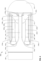
- FIG. 4 depicts a cross-sectional view of the blood outflow cage 110, oriented as depicted in FIG. 3 , and sectioned down its middle along the plane indicated by reference line 4-4 of FIG. 3 .
- struts 204 and 206 are no longer visible, and struts 208 and 210 are now visible.
- an aperture 410 is visible running through the distal end of blood outflow cage 110.
- the aperture 410 runs from a proximal opening 408 in diffuser 212 to a distal opening 412 in end cap 214.
- Aperture 410 is adapted to allow a guide wire to be passed through the distal end of blood outflow cage 110.
- aperture 410 has a larger diameter adapted to couple with a tubular pigtail extension 112.
- aperture 410 is an optional feature, and the present technology may be used with blood outflow cages that do not include aperture 410, or which include apertures of different configurations.
- the sectioned surfaces of blood outflow cage 110 are shown in FIG. 4 with diagonal hatching. This reveals another feature of struts 202, 204, 206, 208, and 210.
- the strut includes a tapered section 404.
- strut 202 has a substantially constant thickness between arrow 414 and arrow 406, and then has a tapered section 404 as the strut 202 transitions into the thinner wall thickness of cylindrical section 201 at arrow 402.
- This tapered section 404 corresponds to the fanning out of strut 202 at the rounded corners 216e and 216a (not visible in this sectional view) of the adjacent openings.
- This tapered section 404 may have any suitable contour and dimension.
- tapered section 404 may taper in a linear or curved manner. If curved, tapered section 404 may be formed using a single radius, or by blending two or more radii. Thus, for a design similar to that shown in FIG.
- tapered section 404 may include (moving distal to proximal) a concave radius of approximately 6.5 mm that transitions into a convex radius of approximately 4.8 mm.
- the wall thickness may taper from approximately 0.4 mm at or about arrow 406 to approximately 0.2 mm at or about arrow 402.
- FIGS. 5A and 5B depict isometric views of the blood outflow cage 110 depicted in FIGS. 2-4 .
- FIG. 5A depicts an isometric view of the exemplary blood outflow cage 110 of FIGS. 2-4 looking in the distal direction
- FIG. 5B depicts an isometric view of the exemplary blood outflow cage 110 of FIGS. 2-4 looking in the proximal direction.
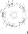
- FIG. 6 depicts a cross-sectional view of the blood outflow cage 110, sectioned along line 6-6 of FIG. 5B looking in the direction of the arrows, i.e., towards the distal end of blood outflow cage 110.
- the sectioned surface of each strut of the blood outflow cage 110 is shown in FIG. 6 with cross hatching.
- the term “coupled” means the joining of two members directly or indirectly to one another. Such joining may be stationary or moveable in nature. Such joining may be achieved with the two members or the two members and any additional intermediate members being integrally formed as a single unitary body with one another or with the two members or the two members and any additional intermediate members being attached to one another. Such joining may be permanent in nature or may be removable or releasable in nature.
- inventive implementations are presented by way of example only and that, within the scope of the appended claims and equivalents thereto, inventive implementations may be practiced otherwise than as specifically described and claimed.
- inventive implementations of the present disclosure are directed to each individual feature, system, article, material, kit, and/or method described herein.
- the phrase "at least one,” in reference to a list of one or more elements, should be understood to mean at least one element selected from any one or more of the elements in the list of elements.
- the phrase “at least one” should not be understood to require at least one of each and every element specifically listed within the list of elements.
- the phrase “at least one” should also not be understood to exclude any combinations of elements in the list of elements. This definition also allows that elements may optionally be present other than the elements specifically identified within the list of elements to which the phrase "at least one" refers, whether related or unrelated to those elements specifically identified.
- “at least one of A and B" can refer, in one implementation, to at least one, optionally including more than one, A, with no B present (and optionally including elements other than B); in another implementation, to at least one, optionally including more than one, B, with no A present (and optionally including elements other than A); in yet another implementation, to at least one, optionally including more than one, A, and at least one, optionally including more than one, B (and optionally including other elements); etc.
Landscapes
- Health & Medical Sciences (AREA)
- Heart & Thoracic Surgery (AREA)
- Engineering & Computer Science (AREA)
- Life Sciences & Earth Sciences (AREA)
- General Health & Medical Sciences (AREA)
- Anesthesiology (AREA)
- Biomedical Technology (AREA)
- Hematology (AREA)
- Cardiology (AREA)
- Animal Behavior & Ethology (AREA)
- Mechanical Engineering (AREA)
- Public Health (AREA)
- Veterinary Medicine (AREA)
- Vascular Medicine (AREA)
- Transplantation (AREA)
- External Artificial Organs (AREA)
- Materials For Medical Uses (AREA)
Applications Claiming Priority (3)
| Application Number | Priority Date | Filing Date | Title |
|---|---|---|---|
| US201962955603P | 2019-12-31 | 2019-12-31 | |
| EP20842845.8A EP4084856B1 (fr) | 2019-12-31 | 2020-12-21 | Cage d'écoulement distal de pompe d'assistance circulatoire |
| PCT/US2020/066389 WO2021138115A1 (fr) | 2019-12-31 | 2020-12-21 | Cage découlement distal de pompe d'assistance circulatoire |
Related Parent Applications (1)
| Application Number | Title | Priority Date | Filing Date |
|---|---|---|---|
| EP20842845.8A Division EP4084856B1 (fr) | 2019-12-31 | 2020-12-21 | Cage d'écoulement distal de pompe d'assistance circulatoire |
Publications (2)
| Publication Number | Publication Date |
|---|---|
| EP4541410A2 true EP4541410A2 (fr) | 2025-04-23 |
| EP4541410A3 EP4541410A3 (fr) | 2025-07-23 |
Family
ID=74191931
Family Applications (2)
| Application Number | Title | Priority Date | Filing Date |
|---|---|---|---|
| EP20842845.8A Active EP4084856B1 (fr) | 2019-12-31 | 2020-12-21 | Cage d'écoulement distal de pompe d'assistance circulatoire |
| EP25154252.8A Pending EP4541410A3 (fr) | 2019-12-31 | 2020-12-21 | Cage d'écoulement distal de pompe à sang |
Family Applications Before (1)
| Application Number | Title | Priority Date | Filing Date |
|---|---|---|---|
| EP20842845.8A Active EP4084856B1 (fr) | 2019-12-31 | 2020-12-21 | Cage d'écoulement distal de pompe d'assistance circulatoire |
Country Status (13)
| Country | Link |
|---|---|
| US (1) | US20210196941A1 (fr) |
| EP (2) | EP4084856B1 (fr) |
| JP (1) | JP2023508518A (fr) |
| KR (1) | KR20220121821A (fr) |
| CN (2) | CN120346441A (fr) |
| AU (1) | AU2020417203A1 (fr) |
| CA (1) | CA3162441A1 (fr) |
| DE (1) | DE112020006406T5 (fr) |
| DK (1) | DK4084856T3 (fr) |
| ES (1) | ES3015192T3 (fr) |
| IL (2) | IL294263B2 (fr) |
| TW (1) | TWI883094B (fr) |
| WO (1) | WO2021138115A1 (fr) |
Families Citing this family (28)
| Publication number | Priority date | Publication date | Assignee | Title |
|---|---|---|---|---|
| DE102018207594A1 (de) | 2018-05-16 | 2019-11-21 | Kardion Gmbh | Rotor, Magnetkupplungsvorrichtung, Elektromotor für ein Herzunterstützungssystem, Pumpeneinheit für ein Herzunterstützungssystem sowie Verfahren zum Herstellen eines Rotors |
| DE102018208549A1 (de) | 2018-05-30 | 2019-12-05 | Kardion Gmbh | Elektronikmodul für ein Herzunterstützungssystem und Verfahren zum Herstellen eines Elektronikmoduls für ein Herzunterstützungssystem |
| DE102018211297A1 (de) | 2018-07-09 | 2020-01-09 | Kardion Gmbh | Herzunterstützungssystem und Verfahren zur Überwachung der Integrität einer Haltestruktur eines Herzunterstützungssystems |
| DE102018211327A1 (de) | 2018-07-10 | 2020-01-16 | Kardion Gmbh | Laufrad für ein implantierbares, vaskuläres Unterstützungssystem |
| DE102018211328A1 (de) | 2018-07-10 | 2020-01-16 | Kardion Gmbh | Laufradgehäuse für ein implantierbares, vaskuläres Unterstützungssystem |
| USD1092716S1 (en) * | 2019-12-31 | 2025-09-09 | Abiomed, Inc. | Outflow cage for blood pump |
| CA3192451A1 (fr) | 2020-09-14 | 2022-03-17 | Johannes Bette | Pompe de support cardiovasculaire dotee d'un impulseur a zone d'ecoulement variable |
| JP2023550938A (ja) | 2020-11-20 | 2023-12-06 | カルディオン ゲーエムベーハー | ガイドワイヤ補助具付き機械的循環支持システム |
| JP2024525097A (ja) | 2021-07-07 | 2024-07-09 | エフビーアール メディカル, インク. | 部分的に変形可能なインペラ及び同インペラを組み込んだカテーテル血液ポンプ |
| CN114984444A (zh) * | 2022-05-24 | 2022-09-02 | 苏州心岭迈德医疗科技有限公司 | 一种导管介入心脏泵 |
| US20250229077A1 (en) * | 2022-08-18 | 2025-07-17 | Rocketheart Technology Co., Ltd | Interventional Blood Pump with Outlet Flow Guide Structure |
| WO2024103207A1 (fr) * | 2022-11-14 | 2024-05-23 | 生命盾医疗技术(苏州)有限公司 | Canule pour pompage d'assistance ventriculaire, et dispositif d'assistance ventriculaire |
| CN116212228B (zh) * | 2023-03-23 | 2026-04-17 | 深圳核心医疗科技股份有限公司 | 血泵远端延伸件、入口窗组件和血泵 |
| CN116726379B (zh) * | 2023-05-31 | 2026-03-27 | 深圳核心医疗科技股份有限公司 | 导丝管、血泵系统及其制造方法 |
| CN116747427B (zh) * | 2023-06-06 | 2026-03-06 | 深圳核心医疗科技股份有限公司 | 血泵 |
| CN117045931A (zh) * | 2023-07-14 | 2023-11-14 | 深圳核心医疗科技股份有限公司 | 送液管、套管组件及血泵 |
| CN117159913A (zh) * | 2023-09-23 | 2023-12-05 | 安徽通灵仿生科技有限公司 | 右心室辅助装置的泵送组件 |
| CN117159915A (zh) * | 2023-09-23 | 2023-12-05 | 安徽通灵仿生科技有限公司 | 一种血液流入笼及其导管泵 |
| US20250121179A1 (en) * | 2023-10-12 | 2025-04-17 | Abiomed, Inc. | Heart pump assembly with a pump housing configured to reduce hemolysis |
| CN117398597A (zh) * | 2023-10-31 | 2024-01-16 | 深圳核心医疗科技股份有限公司 | 血泵 |
| CN117398599A (zh) * | 2023-10-31 | 2024-01-16 | 深圳核心医疗科技股份有限公司 | 血泵 |
| WO2025092212A1 (fr) * | 2023-10-31 | 2025-05-08 | 深圳核心医疗科技股份有限公司 | Pompe à sang |
| CN117398598A (zh) * | 2023-10-31 | 2024-01-16 | 深圳核心医疗科技股份有限公司 | 血泵 |
| CN117398600A (zh) * | 2023-10-31 | 2024-01-16 | 深圳核心医疗科技股份有限公司 | 血泵 |
| WO2025108074A1 (fr) * | 2023-11-21 | 2025-05-30 | 深圳核心医疗科技股份有限公司 | Pompe à sang |
| USD1101157S1 (en) * | 2023-12-20 | 2025-11-04 | Abiomed, Inc. | Medical device housing |
| WO2025201370A1 (fr) * | 2024-03-27 | 2025-10-02 | 生命盾医疗技术(苏州)有限公司 | Ouverture de reflux sanguin asymétrique à faible contrainte de cisaillement et pompe de cathéter d'intervention |
| CN119055946B (zh) * | 2024-11-04 | 2025-03-07 | 航天泰心科技有限公司 | 入口支架及介入式血泵 |
Citations (1)
| Publication number | Priority date | Publication date | Assignee | Title |
|---|---|---|---|---|
| US9433713B2 (en) | 2014-05-13 | 2016-09-06 | Abiomed, Inc. | Blood pump housing component |
Family Cites Families (11)
| Publication number | Priority date | Publication date | Assignee | Title |
|---|---|---|---|---|
| US5354288A (en) * | 1993-02-24 | 1994-10-11 | Minnesota Mining And Manufacturing Company | Low velocity aortic cannula |
| US6007478A (en) * | 1997-11-13 | 1999-12-28 | Impella Cardiotechnik Aktiengesellschaft | Cannula having constant wall thickness with increasing distal flexibility and method of making |
| US20050113631A1 (en) * | 2003-11-12 | 2005-05-26 | Bolling Steven F. | Cannulae having a redirecting tip |
| EP2407187A3 (fr) * | 2010-07-15 | 2012-06-20 | ECP Entwicklungsgesellschaft mbH | Pompe sanguine pour l'application invasive à l'intérieur d'un corps de patient |
| US9821146B2 (en) * | 2015-09-22 | 2017-11-21 | Abiomed, Inc. | Guidewire for cannula placement |
| EP3205360B1 (fr) * | 2016-02-11 | 2018-08-29 | Abiomed Europe GmbH | Pompe sanguine |
| EP3222302B1 (fr) * | 2016-03-23 | 2018-05-16 | Abiomed Europe GmbH | Pompe sanguine avec filtre |
| JP6788792B2 (ja) * | 2016-11-17 | 2020-11-25 | ニプロ株式会社 | カニューレ |
| ES2863628T3 (es) * | 2017-05-04 | 2021-10-11 | Abiomed Europe Gmbh | Bomba de sangre intravascular con balón |
| DE102018208540A1 (de) * | 2018-05-30 | 2019-12-05 | Kardion Gmbh | Pumpengehäusevorrichtung und Verfahren zum Herstellen einer Pumpengehäusevorrichtung und Pumpe mit einer Pumpengehäusevorrichtung |
| US11931560B2 (en) * | 2019-02-26 | 2024-03-19 | White Swell Medical Ltd | Devices and methods for treating edema |
-
2020
- 2020-12-21 ES ES20842845T patent/ES3015192T3/es active Active
- 2020-12-21 CN CN202510552468.XA patent/CN120346441A/zh active Pending
- 2020-12-21 EP EP20842845.8A patent/EP4084856B1/fr active Active
- 2020-12-21 CN CN202080091784.7A patent/CN114929327B/zh active Active
- 2020-12-21 DE DE112020006406.9T patent/DE112020006406T5/de active Pending
- 2020-12-21 WO PCT/US2020/066389 patent/WO2021138115A1/fr not_active Ceased
- 2020-12-21 US US17/128,784 patent/US20210196941A1/en active Pending
- 2020-12-21 JP JP2022540329A patent/JP2023508518A/ja active Pending
- 2020-12-21 IL IL294263A patent/IL294263B2/en unknown
- 2020-12-21 KR KR1020227022694A patent/KR20220121821A/ko active Pending
- 2020-12-21 CA CA3162441A patent/CA3162441A1/fr active Pending
- 2020-12-21 TW TW109145209A patent/TWI883094B/zh active
- 2020-12-21 EP EP25154252.8A patent/EP4541410A3/fr active Pending
- 2020-12-21 DK DK20842845.8T patent/DK4084856T3/da active
- 2020-12-21 AU AU2020417203A patent/AU2020417203A1/en active Pending
-
2025
- 2025-10-30 IL IL324354A patent/IL324354A/en unknown
Patent Citations (1)
| Publication number | Priority date | Publication date | Assignee | Title |
|---|---|---|---|---|
| US9433713B2 (en) | 2014-05-13 | 2016-09-06 | Abiomed, Inc. | Blood pump housing component |
Also Published As
| Publication number | Publication date |
|---|---|
| DK4084856T3 (da) | 2025-03-24 |
| EP4541410A3 (fr) | 2025-07-23 |
| DE112020006406T5 (de) | 2022-10-13 |
| EP4084856A1 (fr) | 2022-11-09 |
| WO2021138115A1 (fr) | 2021-07-08 |
| US20210196941A1 (en) | 2021-07-01 |
| TW202200230A (zh) | 2022-01-01 |
| IL294263B1 (en) | 2025-11-01 |
| ES3015192T3 (en) | 2025-04-30 |
| CN120346441A (zh) | 2025-07-22 |
| EP4084856B1 (fr) | 2025-01-29 |
| CN114929327A (zh) | 2022-08-19 |
| TWI883094B (zh) | 2025-05-11 |
| IL294263A (en) | 2022-08-01 |
| IL294263B2 (en) | 2026-03-01 |
| CN114929327B (zh) | 2025-05-23 |
| AU2020417203A1 (en) | 2022-08-25 |
| CA3162441A1 (fr) | 2021-07-08 |
| IL324354A (en) | 2025-12-01 |
| KR20220121821A (ko) | 2022-09-01 |
| JP2023508518A (ja) | 2023-03-02 |
Similar Documents
| Publication | Publication Date | Title |
|---|---|---|
| EP4084856B1 (fr) | Cage d'écoulement distal de pompe d'assistance circulatoire | |
| US12241480B2 (en) | Blood pump housing component | |
| AU2016326370B2 (en) | Guidewire for cannula placement | |
| US11730946B2 (en) | Flow enhancement for circulatory support device | |
| HK40083700A (en) | Blood pump distal outflow cage | |
| HK40083700B (en) | Blood pump distal outflow cage | |
| HK40049399A (en) | Blood pump housing component | |
| CN119055946B (zh) | 入口支架及介入式血泵 |
Legal Events
| Date | Code | Title | Description |
|---|---|---|---|
| PUAI | Public reference made under article 153(3) epc to a published international application that has entered the european phase |
Free format text: ORIGINAL CODE: 0009012 |
|
| STAA | Information on the status of an ep patent application or granted ep patent |
Free format text: STATUS: THE APPLICATION HAS BEEN PUBLISHED |
|
| AC | Divisional application: reference to earlier application |
Ref document number: 4084856 Country of ref document: EP Kind code of ref document: P |
|
| AK | Designated contracting states |
Kind code of ref document: A2 Designated state(s): AL AT BE BG CH CY CZ DE DK EE ES FI FR GB GR HR HU IE IS IT LI LT LU LV MC MK MT NL NO PL PT RO RS SE SI SK SM TR |
|
| P01 | Opt-out of the competence of the unified patent court (upc) registered |
Free format text: CASE NUMBER: APP_19818/2025 Effective date: 20250424 |
|
| REG | Reference to a national code |
Ref country code: DE Ref legal event code: R079 Free format text: PREVIOUS MAIN CLASS: A61M0060216000 Ipc: A61M0060130000 |
|
| PUAL | Search report despatched |
Free format text: ORIGINAL CODE: 0009013 |
|
| AK | Designated contracting states |
Kind code of ref document: A3 Designated state(s): AL AT BE BG CH CY CZ DE DK EE ES FI FR GB GR HR HU IE IS IT LI LT LU LV MC MK MT NL NO PL PT RO RS SE SI SK SM TR |
|
| RIC1 | Information provided on ipc code assigned before grant |
Ipc: A61M 60/13 20210101AFI20250616BHEP Ipc: A61M 60/81 20210101ALI20250616BHEP Ipc: A61M 60/216 20210101ALI20250616BHEP |
|
| STAA | Information on the status of an ep patent application or granted ep patent |
Free format text: STATUS: REQUEST FOR EXAMINATION WAS MADE |
|
| 17P | Request for examination filed |
Effective date: 20260120 |