EP4541453A1 - Dissolution de particules solides dans un liquide - Google Patents
Dissolution de particules solides dans un liquide Download PDFInfo
- Publication number
- EP4541453A1 EP4541453A1 EP24207635.4A EP24207635A EP4541453A1 EP 4541453 A1 EP4541453 A1 EP 4541453A1 EP 24207635 A EP24207635 A EP 24207635A EP 4541453 A1 EP4541453 A1 EP 4541453A1
- Authority
- EP
- European Patent Office
- Prior art keywords
- liquid
- mixing vessel
- inlet
- outlet
- solid particles
- Prior art date
- Legal status (The legal status is an assumption and is not a legal conclusion. Google has not performed a legal analysis and makes no representation as to the accuracy of the status listed.)
- Pending
Links
Images

Classifications
-
- B—PERFORMING OPERATIONS; TRANSPORTING
- B01—PHYSICAL OR CHEMICAL PROCESSES OR APPARATUS IN GENERAL
- B01F—MIXING, e.g. DISSOLVING, EMULSIFYING OR DISPERSING
- B01F21/00—Dissolving
- B01F21/20—Dissolving using flow mixing
- B01F21/22—Dissolving using flow mixing using additional holders in conduits, containers or pools for keeping the solid material in place, e.g. supports or receptacles
- B01F21/221—Dissolving using flow mixing using additional holders in conduits, containers or pools for keeping the solid material in place, e.g. supports or receptacles comprising constructions for blocking or redispersing undissolved solids
-
- B—PERFORMING OPERATIONS; TRANSPORTING
- B01—PHYSICAL OR CHEMICAL PROCESSES OR APPARATUS IN GENERAL
- B01F—MIXING, e.g. DISSOLVING, EMULSIFYING OR DISPERSING
- B01F25/00—Flow mixers; Mixers for falling materials, e.g. solid particles
- B01F25/20—Jet mixers, i.e. mixers using high-speed fluid streams
- B01F25/21—Jet mixers, i.e. mixers using high-speed fluid streams with submerged injectors, e.g. nozzles, for injecting high-pressure jets into a large volume or into mixing chambers
-
- B—PERFORMING OPERATIONS; TRANSPORTING
- B01—PHYSICAL OR CHEMICAL PROCESSES OR APPARATUS IN GENERAL
- B01F—MIXING, e.g. DISSOLVING, EMULSIFYING OR DISPERSING
- B01F25/00—Flow mixers; Mixers for falling materials, e.g. solid particles
- B01F25/30—Injector mixers
- B01F25/31—Injector mixers in conduits or tubes through which the main component flows
- B01F25/312—Injector mixers in conduits or tubes through which the main component flows with Venturi elements; Details thereof
- B01F25/3124—Injector mixers in conduits or tubes through which the main component flows with Venturi elements; Details thereof characterised by the place of introduction of the main flow
- B01F25/31242—Injector mixers in conduits or tubes through which the main component flows with Venturi elements; Details thereof characterised by the place of introduction of the main flow the main flow being injected in the central area of the venturi, creating an aspiration in the circumferential part of the conduit
-
- B—PERFORMING OPERATIONS; TRANSPORTING
- B01—PHYSICAL OR CHEMICAL PROCESSES OR APPARATUS IN GENERAL
- B01F—MIXING, e.g. DISSOLVING, EMULSIFYING OR DISPERSING
- B01F25/00—Flow mixers; Mixers for falling materials, e.g. solid particles
- B01F25/50—Circulation mixers, e.g. wherein at least part of the mixture is discharged from and reintroduced into a receptacle
- B01F25/53—Circulation mixers, e.g. wherein at least part of the mixture is discharged from and reintroduced into a receptacle in which the mixture is discharged from and reintroduced into a receptacle through a recirculation tube, into which an additional component is introduced
-
- B—PERFORMING OPERATIONS; TRANSPORTING
- B01—PHYSICAL OR CHEMICAL PROCESSES OR APPARATUS IN GENERAL
- B01F—MIXING, e.g. DISSOLVING, EMULSIFYING OR DISPERSING
- B01F2101/00—Mixing characterised by the nature of the mixed materials or by the application field
- B01F2101/06—Mixing of food ingredients
- B01F2101/14—Mixing of ingredients for non-alcoholic beverages; Dissolving sugar in water
Definitions
- the invention relates to the field of food production. More particularly, it is related to a system for dissolving solid particles in a liquid and to a method of dissolving solid particles in a liquid.
- the system has a tank configured to hold the liquid and a pre-mixing vessel or tank.
- Whren powdered dry bulk ingredients like sugar, dextrose, citric acid and similar are stored in humid conditions or for a prolonged period of time, it is common that powder formations such as lumps or pebbles are formed inside the package of the dry powdered bulk ingredients. Such lump formation is even more outspoken for some products which are prone to form lumps.
- Powdered ingredients of the above type are typically distributed and stored in bags. Such bags may be of very different sizes spanning from e.g., a few 100 grams to several tones.
- any lumps or pebbles formed by the bulk ingredients themselves will also have to be dissolved or else the final product will have an inferior quality with lumps in it.
- Dissolving of lumps of powdered ingredients is typically troublesome for instance because when a lump of a dry powder is subjected to a liquid, the outermost portion of the lump generally absorbs the liquid while forming a high concentration ingredient shell around the interior of the lump. After formation of such high concentration ingredient shell, it is generally time-consuming to dissolve a lump since the high concentration ingredient shell efficiently prevents or delays water from reaching the interior of the lump.
- Another object is to provide such a system and method which are more efficient when it comes to dissolving solid particles including solid particle lumps in a liquid.
- Another object is to provide such a system and method which are capable of handling a wider range of solid particles.
- Another object is to provide such a system and method which are capable of handling a solid particles having different qualities.
- Another object is to provide such a system and method which are less labor intensive.
- Another object is to provide such a system and method which are more cost-efficient.
- a system for dissolving solid particles in a liquid having the features defined in claim 1 is provided according to the present inventive concept.
- a method of dissolving solid particles in a liquid is provided according to claim 12. Preferred variations of the inventive concept will be evident from the dependent claims.
- a system for dissolving solid particles in a liquid comprising: a tank configured to hold the liquid, the tank comprising a tank outlet and a tank inlet, a circulation line configured to circulate the liquid over the tank, the circulation line extending from the tank outlet to the tank inlet, a pre-mixing vessel configured to receive and dissolve the solid particles in the liquid to form a mixture, the pre-mixing vessel comprising a first inlet for receiving the liquid, a second inlet for receiving the solid particles and an outlet for the mixture, and a venturi injector configured to inject the mixture into the circulation line, the venturi injector comprising a pressure inlet, an outlet and a suction inlet, the venturi injector being arranged in the circulation line by being connected thereto by the pressure inlet and the outlet, wherein the suction inlet of the venturi injector is connected to the outlet of the pre-mixing vessel, such that the mixture in the pre-mixing vessel can be drawn from the pre-mix
- the present invention is based on the realization that solid particles may efficiently be dissolved in a liquid by utilizing a pre-mixing vessel in combination with a venturi injector.
- a pre-mixing vessel in combination with a venturi injector.
- the system may efficiently handle solid particles including solid particle lumps with a significantly reduced risk of getting clogged or otherwise ruined.
- the venturi injector of the system is generally speaking insensitive to aspiring or drawing in solid particles or solid particle lumps. This means that even if the solid particles of the mixture are not completely dissolved or if the mixture includes solid particle lumps, the venturi injector may still draw the mixture from the pre-mixing vessel and inject the mixture into the circulation line. This means that the mixture may be mixed with and form part of the liquid when the liquid is circulated in the circulation line irrespective of if the solid particles have been completely dissolved in the pre-mixing vessel or not.
- a system which is highly capable of dissolving solid particles in a liquid even when the solid particles include solid particle lumps may be achieved according to the present invention.
- the system may further comprise a liquid feed line extending from the circulation line upstream the venturi injector to the first inlet of the pre-mixing vessel, such that the liquid can be fed to the pre-mixing vessel via the first inlet when the liquid is circulated in the circulation line, which is advantageous in that liquid from the tank which is circulated may be used to dissolve the solid particles in the pre-mixing vessel.
- a liquid feed line extending from the circulation line upstream the venturi injector to the first inlet of the pre-mixing vessel, such that the liquid can be fed to the pre-mixing vessel via the first inlet when the liquid is circulated in the circulation line, which is advantageous in that liquid from the tank which is circulated may be used to dissolve the solid particles in the pre-mixing vessel.
- one and the same liquid may be used to dissolve the solid particles in the pre-mixing vessel and serve as a final product in which the solid particles are dissolved.
- any amount of liquid needed to dissolve the solid particles in the pre-mixing vessel may be fed to the pre-mixing vessel
- a large amount of liquid may be fed to the pre-mixing vessel and used to dissolve the solid particles without risking that the overall amount of liquid in the system and hence the tank becomes too large.
- a single pump may be used to circulate the liquid in the circulation line and to feed the liquid to the pre-mixing vessel.
- the system may further comprise a level sensor configured to determine a level of the liquid in the pre-mixing vessel, and a liquid feed valve arranged in the liquid feed line, wherein the liquid feed valve is configured to open in response to the level sensor generating a first signal indicative of the level of the liquid in the pre-mixing vessel being below a first predetermined level, and to close in response to the level sensor generating a second signal indicative of the level of the liquid in the pre-mixing vessel being above a second predetermined level, which is advantageous in that the level of the liquid in the pre-mixing vessel may be keep within an interval in which efficient dissolving of the solid particles at hand may take place.
- the level sensor may be a pressure sensor arranged at the bottom region of the pre-mixing vessel.
- the level sensor may be a flotation sensor.
- the level sensor may be a radar sensor to give a few non-limiting examples.
- first predetermined level and the second predetermined level may be adjusted depending on the type of solid particles.
- the wording "to open” and the wording “to close” may refer to any state of the liquid feed valve in which the valve is moved to a more open state and to a more closed state respectively.
- the valve may open partially or completely and correspondingly close partially or completely.
- the system may further comprise a circulation pump configured to circulate the liquid through the circulation line, the circulation pump being arranged in the circulation line upstream the liquid feed line, which is advantageous in that the circulation pump may be used to circulate the liquid in the circulation line as well to fed liquid to the pre-mixing vessel via the liquid feed line.
- a circulation pump configured to circulate the liquid through the circulation line, the circulation pump being arranged in the circulation line upstream the liquid feed line, which is advantageous in that the circulation pump may be used to circulate the liquid in the circulation line as well to fed liquid to the pre-mixing vessel via the liquid feed line.
- the outlet of the pre-mixing vessel may be provided at a bottom portion of the pre-mixing vessel and the first inlet of the pre-mixing vessel may be provided above the outlet of the pre-mixing vessel, which is advantageous in that the outlet of the pre-mixing vessel may be flushed or at least partially kept clear from solid particles by the liquid entering the pre-mixing vessel through the first inlet thereof.
- liquid entering the pre-mixing vessel through the first inlet thereof may assist in keeping the outlet open or free or substantially free of solid particles or solid particle lumps.
- the first inlet of the pre-mixing vessel may comprise a nozzle configured to distribute the liquid received via the first inlet of the pre-mixing vessel in a plurality of directions, which is advantageous in that the liquid may be efficiently distributed throughout the pre-mixing vessel and hence throughout the solid particles. Further, by distributing the liquid in a plurality of directions, a turbulent flow efficiently dissolving the solid particles in the liquid may be obtained. Furthermore, by distributing the liquid in a plurality of directions the bottom region of the pre-mixing vessel and details of the pre-mixing vessel associated with the bottom region may be flushed such that accumulation of solid particles may be prevented or counteracted.
- the first inlet of the pre-mixing vessel may comprise a nozzle configured to distribute the liquid received via the first inlet of the pre-mixing vessel in at least a horizontal direction.
- the first inlet of the pre-mixing vessel may comprise a nozzle configured to distribute the liquid received via the first inlet of the pre-mixing vessel in a plurality of directions, including at least a horizontal direction.
- the nozzle may comprise a liquid distribution element arranged vertically above the first inlet of the pre-mixing vessel, and having a major bottom surface extending in a horizontal plane perpendicular to the first inlet of the pre-mixing vessel, such that the liquid received via the first inlet of the pre-mixing vessel impinges on the major bottom surface of the liquid distribution element and is distributed in at least one horizontal direction, which is advantageous in that the liquid may be efficiently distributed throughout the pre-mixing vessel and hence throughout the solid particles. Further, by distributing the liquid in at least one horizontal direction, a turbulent flow efficiently dissolving the solid particles in the liquid may be obtained. Furthermore, by distributing the liquid in at least one horizontal direction the bottom region of the pre-mixing vessel and details of the pre-mixing vessel associated with the bottom region may be efficiently flushed such that accumulation of solid particles may be prevented or counteracted.
- the pre-mixing vessel may further comprise a sieve arranged below the first and the second inlets of the pre-mixing vessel and above the outlet of the mixing vessel for preventing solid particles above a predetermined size to enter the outlet of the mixing vessel.
- the sieve may efficiently prevent or counteract solid particles or solid particle lumps above a predetermined size form reaching the venturi injector.
- the sieve may be a strainer.
- the sieve may be any device for blocking big particles or lumps but letting small through.
- the sieve may efficiently block solid particle lumps above a certain size while letting solid particles and smaller lumps through.
- the sieve may have a maximum opening dimension of about 15 mm. Hence, the sieve openings may be about 15 mm across their widest section.
- the sieve may include a mesh or a grid.
- the sieve may be a mesh or a grid.
- the nozzle may be arranged to create a turbulent flow of fluid above an upper surface of the sieve, which is advantageous in that the solid particles and solid particle lumps may be efficiently dissolved and mixed. Further, by creating a turbulent flow of fluid above an upper surface of the sieve, solid particle lumps which are too large to pass through the sieve may be efficiently affected by the turbulent flow and hence dissolved in the liquid. Furthermore, solid particle lumps which are too large to pass through the sieve may be stirred or moved around such that the sieve is counteracted from getting clogged or blocked.
- a turbulent flow of fluid is here meant to mean any turbulent flow of the liquid as well as any turbulent flow of a mixture of the liquid and a gas, such as air.
- the receiving of the liquid may comprise, receiving, via a liquid feed line extending from the circulation line upstream the venturi injector to the first inlet of the pre-mixing vessel, the liquid at the pre-mixing vessel.
- the circulating of the liquid from the tank through the venturi injector may comprise, keeping a level of the liquid in the tank above the level the liquid in the pre-mixing vessel, which is advantageous in that solid powder may be added at level below to liquid level in the tank.
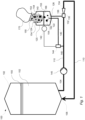
- FIG. 1 schematically illustrates by way of example an exemplary system 100 for dissolving solid particles 150 in a liquid 152.
- the system 100 is primarily designed to gradually dissolve solid particles in the liquid 152 as the liquid is circulated over a tank 102.
- the tank 102 is configured to hold the liquid 152, i.e. the liquid 152 in which the solid particles 150 typically are to be gradually dissolved. This means that the tank 102 may hold only the liquid 152 before any solid particles are dissolved in the liquid 152. It also means that the tank 102 may hold the liquid 152 with solid particles 152 dissolved therein. The tank may thus hold the liquid 152 and the solid particles 152 dissolved therein in any concentration between an initial concentration, normally with no dissolved solid particles 152, and a final concentration where a desired final amount of solid particles have been dissolved in the liquid 152.
- the depicted tank 102 comprises a tank outlet 104 and a tank inlet 106.
- the tank outlet 104 and the tank inlet 106 are both in fluid communication with the interior of the tank 102.
- a circulation line 110 extends from the tank outlet 104 to the tank inlet 106.
- the circulation line 100 configured to circulate the liquid 152 over the tank 102.
- the circulation line 110 is designed to feed liquid from the tank outlet 104 and back to the tank inlet 106 as generally indicated by the arrow in Fig. 1 .
- the depicted system 100 further comprises a pre-mixing vessel 120.
- the pre-mixing vessel is configured to receive and dissolve the solid particles 150 in the liquid 152 to form a mixture 153.
- the solid particles 150 and the liquid may be received or introduced in the pre-mixing vessel 120 in any order or simultaneously.
- the solid particles 150 may be received first in the pre-mixing vessel 120 and the liquid 152 may be received subsequent to receiving the solid particles 150.
- the liquid 152 may be received first in the pre-mixing vessel 120 and the solid particles 150 may be received subsequent to receiving the liquid 152.
- the solid particles 150 and the liquid may be received simultaneously at the pre-mixing vessel 120.
- the solid particles 150 and the liquid may be received at the pre-mixing vessel 120 at times at least partially overlapping each other.
- the depicted pre-mixing vessel 120 has first inlet 122 for receiving the liquid 152 and a second inlet 124 for receiving the solid particles 150.
- the first inlet 122 is consequently a liquid inlet configured to receive the liquid 152.
- the liquid 152 may typically be received from the tank 102 as depicted in Fig. 1 .
- the liquid 152 in which the solid particles 150 are to be dissolved may be received directly from e.g., a water supply such as a water tap.
- the second inlet 124 is consequently a solid particle inlet or powder inlet.
- the second inlet 124 is typically provided at a top region of the pre-mixing vessel 120.
- the second inlet 124 typically has a relatively speaking large cross-sectional area such that bags 170 with solid particles 150 or powder may be emptied into the second inlet 124. Further, the fact that the second inlet 124 typically has a relatively speaking large cross-sectional area brings about that solid particles 150 including solid particle lumps 154 may be received through the second inlet 124.
- the depicted pre-mixing vessel 120 has an outlet 126 for the mixture 153.
- the outlet 126 of the pre-mixing vessel 120 is provided at a bottom region of the pre-mixing vessel 120 as depicted in Fig. 1 .
- pre-mixing vessel 120 Further details of the pre-mixing vessel 120 will be described later below with reference to Fig. 2 . However, before describing the pre-mixing vessel 120 in detail, the remaining overall functionality of the system 100 will be described first while still mainly referring to Fig. 1 .
- the depicted system 100 further comprises a venturi injector 130.
- the venturi injector 130 is as such a well know device meaning that its function will not be described in detail here.
- a venturi injector 130 relies on the venturi principle and may be used to create an under pressure by feeding a fluid through it. The so created under pressure may be used to draw or suck a different fluid, liquid or gas, into the fluid which creates the under pressure while being fed through the venturi injector 130.
- the venturi injector 130 of the depicted system 100 is configured to inject the mixture 153 of the pre-mixing vessel 120 into the circulation line 110.
- the venturi injector 130 has a pressure inlet 132 and an outlet 134.
- the venturi injector 130 is arranged in the circulation line 110 by being connected thereto by the pressure inlet 132 and the outlet 134.
- the venturi injector 130 further has a suction inlet 136.
- the suction inlet 136 of the venturi injector 130 is connected to the outlet 126 of the pre-mixing vessel 120.
- This configuration of the venturi injector 130 and the circulation line 110 results in that the mixture 153 in the pre-mixing vessel 120 can be drawn from the pre-mixing vessel 120 and be injected into the circulation line 110 when the liquid 152 is circulated in the circulation line 110. It also results in that when the mixture 153 is injected into the circulation line 110, the mixture will be mixed with and form part of the liquid 152. Hence, the liquid 152 will while being circulated in the circulation line 110 receive more and more of the mixture 153 such that the concentration of the dissolved solid particles 150 in the mixture will gradually increase.
- system 100 may typically be operated or actuated until a desired amount of solid particles 150 have been dissolved in the liquid 152.
- the depicted system of Fig. 1 further comprises a liquid feed line 140.
- the depicted liquid feed line 140 extends from the circulation line 110 upstream the venturi injector 130 to the first inlet 122 of the pre-mixing vessel 120.
- the liquid 152 can be fed to the pre-mixing vessel 120 via the first inlet 122 when the liquid 152 is circulated in the circulation line 110.
- the liquid 152 of the tank 102 may be fed to the pre-mixing vessel 120 via the circulation line 110 and the liquid feed line 140 while the liquid is circulated in the circulation line 110.
- any desired amount of the liquid 152 may be fed to the pre-mixing vessel 120 without increasing the overall amount of liquid 152 in the system 100.
- a lot of liquid 152 may be used to dissolve the solid particles 150 without increasing the overall amount of liquid 152.
- the liquid feed line 140 extends from the circulation line 110 upstream the venturi injector 130 brings about that liquid 152 which comes directly from the tank 102 may be fed to the pre-mixing vessel 120.
- the mixture 153 being injected into the circulation line 110 by the venturi injector 130 will in practice not affect how the liquid 152 is fed to the pre-mixing vessel 120 via the liquid feed line 140.
- the depicted system of Fig. 1 further comprises a circulation pump 145.
- the depicted circulation pump 145 is configured and hence designed to circulate the liquid 152 through the circulation line 110.
- the circulation pump 145 is arranged in the circulation line 110 upstream the liquid feed line 140. This means that the circulation pump 145 may not only be used to circulate the liquid 152 in the circulation line but also to feed the liquid to the pre-mixing vessel 120 via the liquid feed line 140. Any suitable type of circulation pump may be used to advantage.
- the liquid 152 may alternatively be fed to the first inlet 122, i.e., the liquid inlet 122, of the pre-mixing vessel 120 via a liquid feed line (not shown) which may be arranged directly from the tank 102 to the to the first inlet 122 of the pre-mixing vessel 120.
- a separate pump or similar will be required to feed the liquid 152 directly to the to the first inlet 122 of the pre-mixing vessel 120 unless the liquid level 155 of the tank 102 is above the level 143 of the liquid 152 in the pre-mixing vessel 120.
- a pump or similar may typically be required to achieve a desired mass flow and/or flow speed of the liquid 152.
- the depicted system of Fig. 1 further comprises a liquid feed valve 144 arranged in the liquid feed line 140.
- the liquid feed valve 144 may be used to open and close the liquid feed line 140 such that liquid may or may not be fed to the pre-mixing vessel 120. Further, the liquid feed valve 144 may be used to control the flow of liquid 152 through the liquid feed line 140. Any type of suitable valve may be used to advantage as the liquid feed valve 144.
- the depicted liquid feed valve 144 is configured to open in response to the level sensor 142 generating a first signal indicative of the level 134 of the liquid 152 in the pre-mixing vessel 120 being below a first predetermined level. Further, depicted liquid feed valve 144 is configured to close in response to the level sensor 142 generating a second signal indicative of the level 143 of the liquid 152 in the pre-mixing vessel 120 being above a second predetermined level. In this way, the level 143 of the liquid 152 in the pre-mixing vessel may be kept within an interval defined by the first predetermined level and the second predetermined level.
- liquid 152 different types of solid particles 150 are typically efficiently dissolved in different amounts of liquid 152.
- the first predetermined level and the second predetermined level may to advantage be adjusted to in relation to the type of solid particles 150 presently being dissolved in the system 100.
- different amounts of liquid 152 in the pre-mixing vessel may be used to advantage for e.g., powdered sugar and powdered citric acid.
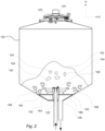
- Fig. 2 is a detailed schematic cross-sectional view of the pre-mixing vessel 120 of the system 100 of Fig. 1 .
- Fig. 2 details the interior of the pre-mixing vessel 120 of Fig. 1 in cross-section through its center.
- the premixing vessel 120 may be generally formed as a tank.
- the pre-mixing vessel 120 may also be referred to as a pre-mixing tank or a mixing tank.
- the second inlet 124 i.e., the solid particle or powder inlet, of the pre-mixing vessel 120 is provided at the top of the pre-mixing vessel 120.
- the second inlet 124 of the pre-mixing vessel 120 is provided with a lid 125 which may be opened when the solid particles 150 or powder is received in the pre-mixing vessel 120.
- the lid 125 may be closed at other times, such as when the solid particles 150 are dissolved in the liquid 152.
- the lid 125 may also be closed to protect the interior of the pre-mixing vessel 120 from contaminations or similar.
- a pile of solid particles will typically build up in the pre-mixing vessel 120 as illustrated in phantom in Fig. 2 .
- Such pile of solid particles 150 may build up irrespective of liquid 152 is present in the pre-mixing vessel 120 or not.
- the solid particles 150 may or may not include solid particle lumps 154 as illustrated in phantom in Fig. 2 .
- the outlet 126 of the depicted pre-mixing vessel is provided at a bottom portion of the pre-mixing vessel 120. More specifically, the outlet is provided at the side of the center of the pre-mixing vessel 120.
- the first inlet 122 i.e., the liquid inlet, of the pre-mixing vessel 122 is provided above the outlet 126 of the pre-mixing vessel 120.
- the first inlet 122 is provided vertically above the outlet 126 in the vertical direction V of the pre-mixing vessel 120.
- liquid 152 which enters the pre-mixing vessel 120 may flush the outlet 126 and thereby prevent or counteract that the outlet 126 is clogged or otherwise blocked by solid particles 150 or solid particle lumps 154. Further, by this arrangement, of the first inlet 122 in relation to the outlet 126, liquid 152 which enters the pre-mixing vessel 120 may create turbulence above the outlet 126 in the vertical direction V and thereby prevent or counteract that the outlet 126 is clogged or otherwise blocked by solid particles 150 or solid particle lumps 154.
- the effect of the liquid 152 agitating, mixing or stirring the solid particles 150 may be further enhanced by the first inlet 122 of the pre-mixing vessel 120 comprising a nozzle 160 as depicted in Fig. 2 .
- the depicted nozzle 160 is configured and hence designed to distribute the liquid 152 received via the first inlet 122 of the pre-mixing vessel 120 in a plurality of directions D.
- the liquid 152 may be distributed in a plurality of directions D including at least a horizontal H direction.
- the liquid 152 is typically distributed in a plurality of directions as indicated by the hatched arrows in Fig. 2 .
- the liquid 152 may be distributed in a fashion where the liquid 152 leaves the nozzle 160 while having a horizontal component in the horizontal direction H and/or a vertical component in the vertical direction V.
- the depicted nozzle 160 of Fig. 2 comprises a liquid distribution element 162.
- the liquid distribution element 162 is arranged vertically above the first inlet 122 of the pre-mixing vessel 120. Hence the liquid distribution element 162 is arranged above the first inlet 122 of the pre-mixing vessel 120 in the vertical direction V.
- the depicted liquid distribution element 162 has a major bottom surface 164 which extends in a horizontal plane perpendicular to the first inlet 122 of the pre-mixing vessel 120. In other words, the major bottom surface 164 extends along the vertical direction V of the pre-mixing vessel 120.
- the liquid 152 received via the first inlet 122 of the pre-mixing vessel 122 impinges on the major bottom surface 164 of the liquid distribution element 162 and is distributed in at least one horizontal direction D.
- the liquid 152 which is received via the first inlet 122 of the pre-mixing vessel 122 and impinges on the major bottom surface 164 of the liquid distribution element 162 is typically distributed in a plurality of directions D as indicated in Fig. 2 by the hatched arrows.
- the effect of the liquid 152 agitating, mixing or stirring the solid particles 150 may be further enhanced by the liquid distribution element 162.
- the liquid distribution element 162 may create a turbulent flow which may further enhance the effect of the liquid 152 agitating, mixing or stirring the solid particles 150. Such turbulent flow is illustrated by the hatched circular arrows of Fig. 2 .
- the effect of flushing the outlet 126 and thereby preventing or counteracting that the outlet 126 from getting is clogged may be further enhanced by the nozzle 160.
- the effect of flushing the outlet 126 and thereby preventing or counteracting that the outlet 126 from getting is clogged may be further enhanced by the nozzle 160 comprising a liquid distribution element 162.
- the depicted pre-mixing vessel of Fig. 2 further comprises a sieve 166.
- the depicted sieve 166 is arranged below the first 122 and the second 124 inlets of the pre-mixing vessel 120.
- the depicted sieve 166 is arranged above the outlet 126 of the pre-mixing vessel 120. In other words, the sieve 166 is arranged between the inlets 122, 124 and the outlet 126 in the vertical direction V.
- the depicted sieve 166 extends in a plane extending along the horizontal direction H.
- the depicted sieve 166 extends over a complete cross section of the pre-mixing vessel 120 and is only penetrated by the nozzle 160 of the first inlet 122 such that the first inlet 122 and the nozzle 160 are arranged above the sieve 166.
- the sieve 166 is designed for preventing solid particles 150 above a predetermined size to enter the outlet 126 of the mixing vessel 120.
- the sieve 166 is designed for preventing solid particle lumps 164 above a predetermined size to enter the outlet 126 of the mixing vessel 120.
- the sieve 166 may be a strainer, a mesh or a grid to give a few non-limiting examples.
- the sieve 166 may be any type of device any device blocking big particles but letting small through.
- the sieve 166 may for example have openings which are 15 mm across their widest section. Other sizes of openings may however be used to advantage.
- the nozzle 160 may typically be arranged to create a turbulent flow above the upper surface 167 of the sieve 166.
- the depicted nozzle 160 is arranged to eject the liquid 152 in a direction that has a directional component which is parallel to the upper surface 167 of the sieve 166.
- the depicted nozzle 160 is arranged in the bottom fifth part or region of the pre-mixing vessel 120.
- the depicted nozzle 160 is arranged in a lower part of the pre-mixing vessel 120, at a height inside the pre-mixing vessel 120 that is less than 20% of the total interior height of the pre-mixing vessel 120.
- the sieve 166 may be kept clear by the liquid 152 circulating in the volume above the sieve 166. In yet other words, the sieve 166 may be kept clear by the liquid 152 creating turbulence in the volume above the sieve 166.
- the solid particles 150 which are dissolved in the liquid 152 by using the system 100 may typically comprise one or more solid particle lumps 154 having a minimum extension of 80 mm or more.
- Some types of solid particles 150 are prone to forming solid particle lumps 154. This means that for some types of solid particles 150 at least 10 wt% the solid particles 150 may have the form of at least one solid particle lump 154 that has an extension of at least 40 mm. This may for instance be the case when the solid particles 150 include powdered sugar and/or powdered citric acid. Such solid particle lumps 154 may come in any size ranging from more or less the size of a complete bag to small lumps of a few millimeters or less.
- the solid particles 150 may include solid particle lumps 154 may be efficiently accounted for and handled by the system 100 as have been thoroughly described above.
- the solid particles 150 which are dissolved in the liquid 152 by using the system 100 may typically comprise a food material which is dissolvable in water.
- the liquid 152 may typically be a mixture of water and the dissolved solid particles 150.
- the liquid 152 may be water prior to any solid particles 150 being dissolved therein.
- a method 200 for dissolving solid particles 150 in a liquid 152 will be described.
- the method 200 may be performed by using a system 100 of the above-described kind.
- the method may be performed while using a system 100 comprising: a tank 102 comprising a tank outlet 104 and a tank inlet 106, a circulation line 110 extending from the tank outlet 104 to the tank inlet 106, a pre-mixing vessel 120 comprising a first inlet 122, a second inlet 124 and an outlet 126, and a venturi injector 130 comprising a pressure inlet 132, an outlet 134 and a suction inlet 136, wherein the venturi injector 130 is arranged in the circulation line 110 by being connected thereto by the pressure inlet 132 and the outlet 134, and wherein the suction inlet 136 of the venturi injector 130 is connected to the outlet 126 of the pre-mixing vessel 120.
- the method 200 starts by receiving 202, via the second inlet 124 of the pre-mixing vessel 120, the solid particles 152 at the pre-mixing vessel 120.
- the method proceeds by receiving 204, via the first inlet 122 of the pre-mixing vessel 120, the liquid 152 at the pre-mixing vessel 120.
- the method proceeds by dissolving 206, at the pre-mixing vessel 120, the liquid 152 and the solid particles 150, thereby forming a mixture 153.
- the method proceeds by circulating 208, via the circulation line 110, the liquid 152 from the tank 102 through the venturi injector 130 by feeding the liquid 152 into the pressure inlet 132 of the venturi injector 130 and out of the outlet 134 of the venturi injector 130, such that the mixture 153 is drawn from the pre-mixing vessel 120 and injected into the liquid 152 of the circulation line 110 thereby mixing the mixture 153 with the liquid 152 to form part thereof.
- the receiving 204 of the liquid may optionally 152 comprise, receiving, via a liquid feed line 140 extending from the circulation line 100 upstream the venturi injector 130 to the first inlet 122 of the pre-mixing vessel 120, the liquid 152 at the pre-mixing vessel 120.
- the circulating 208 of the liquid 152 from the tank 102 through the venturi injector 130 may optionally comprise, keeping a level 155 of the liquid 152 in the tank 102 above the level 143 of the liquid 152 in the pre-mixing vessel 120.
- the system 100 and the method 200 may be used to efficiently dissolve solid particles 150 in a liquid 152 irrespective of the solid particles 150 include solid particle lumps 154 or not.
Landscapes
- Chemical & Material Sciences (AREA)
- Chemical Kinetics & Catalysis (AREA)
Applications Claiming Priority (1)
| Application Number | Priority Date | Filing Date | Title |
|---|---|---|---|
| EP23204791 | 2023-10-20 |
Publications (1)
| Publication Number | Publication Date |
|---|---|
| EP4541453A1 true EP4541453A1 (fr) | 2025-04-23 |
Family
ID=88506706
Family Applications (1)
| Application Number | Title | Priority Date | Filing Date |
|---|---|---|---|
| EP24207635.4A Pending EP4541453A1 (fr) | 2023-10-20 | 2024-10-18 | Dissolution de particules solides dans un liquide |
Country Status (2)
| Country | Link |
|---|---|
| EP (1) | EP4541453A1 (fr) |
| WO (1) | WO2025083259A1 (fr) |
Citations (3)
| Publication number | Priority date | Publication date | Assignee | Title |
|---|---|---|---|---|
| WO2013050981A1 (fr) * | 2011-10-06 | 2013-04-11 | Marchi & Brevetti Interprise S.R.L. Con Unico Socio | Dispositif et procédé pour dissoudre une substance chimique dans de l'eau |
| WO2018175811A1 (fr) * | 2017-03-22 | 2018-09-27 | Isopure, Corp. | Procédé et système de mélange d'un acide |
| US10252282B2 (en) * | 2015-02-10 | 2019-04-09 | Exel Industries | Mixer for drawing and mixing a solid product with a liquid from a tank of a sprayer |
-
2024
- 2024-10-18 EP EP24207635.4A patent/EP4541453A1/fr active Pending
- 2024-10-18 WO PCT/EP2024/079584 patent/WO2025083259A1/fr active Pending
Patent Citations (3)
| Publication number | Priority date | Publication date | Assignee | Title |
|---|---|---|---|---|
| WO2013050981A1 (fr) * | 2011-10-06 | 2013-04-11 | Marchi & Brevetti Interprise S.R.L. Con Unico Socio | Dispositif et procédé pour dissoudre une substance chimique dans de l'eau |
| US10252282B2 (en) * | 2015-02-10 | 2019-04-09 | Exel Industries | Mixer for drawing and mixing a solid product with a liquid from a tank of a sprayer |
| WO2018175811A1 (fr) * | 2017-03-22 | 2018-09-27 | Isopure, Corp. | Procédé et système de mélange d'un acide |
Also Published As
| Publication number | Publication date |
|---|---|
| WO2025083259A1 (fr) | 2025-04-24 |
Similar Documents
| Publication | Publication Date | Title |
|---|---|---|
| CN101600378B (zh) | 由可溶配料和稀释剂生产泡沫液体的装置和方法 | |
| FI74408C (fi) | Anordning foer kontinuerlig framstaellning av staerkelsemjoelk. | |
| US12070727B2 (en) | Device and method for mixing the contents of a tank | |
| US20030090957A1 (en) | Auger fed mixer apparatus and method of using | |
| PT710148E (pt) | Aparelho e processo para a dissolucao de um solido em particulas num liquido | |
| KR101676046B1 (ko) | 응집제 용해 장치 | |
| EP4541453A1 (fr) | Dissolution de particules solides dans un liquide | |
| JPS643479Y2 (fr) | ||
| US3207485A (en) | Apparatus for producing liquid mixture | |
| JP2834669B2 (ja) | 粉粒体混練装置 | |
| AU2009253157A1 (en) | Mixing assembly comprising a mixing chamber and an overflow chamber and process for mixing | |
| JP4745935B2 (ja) | 凝集剤溶解装置 | |
| JPH1176782A (ja) | 粉体材料の連続混合システム | |
| JP4850729B2 (ja) | 粉体と液体の混合方法及びその装置 | |
| JP2782924B2 (ja) | 粉体と水との混和槽 | |
| CN110606384A (zh) | 一种智能化自动上料系统 | |
| CN203725079U (zh) | 糖蜜稀释装置 | |
| JPH0150447B2 (fr) | ||
| JPH0760091A (ja) | 粉体と液体の連続混合装置 | |
| JP2008049259A (ja) | 粉粒体の循環装置 | |
| JPH09155334A (ja) | 粉末活性炭注入装置 | |
| CN219359854U (zh) | 制浆机 | |
| JP3679903B2 (ja) | 粉体の溶解懸濁装置 | |
| CN206836172U (zh) | 一种饲料搅拌机 | |
| JP3225839B2 (ja) | 粉体と液体の混合方法及び混合装置 |
Legal Events
| Date | Code | Title | Description |
|---|---|---|---|
| PUAI | Public reference made under article 153(3) epc to a published international application that has entered the european phase |
Free format text: ORIGINAL CODE: 0009012 |
|
| STAA | Information on the status of an ep patent application or granted ep patent |
Free format text: STATUS: THE APPLICATION HAS BEEN PUBLISHED |
|
| AK | Designated contracting states |
Kind code of ref document: A1 Designated state(s): AL AT BE BG CH CY CZ DE DK EE ES FI FR GB GR HR HU IE IS IT LI LT LU LV MC ME MK MT NL NO PL PT RO RS SE SI SK SM TR |
|
| STAA | Information on the status of an ep patent application or granted ep patent |
Free format text: STATUS: REQUEST FOR EXAMINATION WAS MADE |
|
| 17P | Request for examination filed |
Effective date: 20251023 |