EP4541633A1 - Instrumententafel und kraftfahrzeug mit einer solchen instrumententafel - Google Patents
Instrumententafel und kraftfahrzeug mit einer solchen instrumententafel Download PDFInfo
- Publication number
- EP4541633A1 EP4541633A1 EP24206839.3A EP24206839A EP4541633A1 EP 4541633 A1 EP4541633 A1 EP 4541633A1 EP 24206839 A EP24206839 A EP 24206839A EP 4541633 A1 EP4541633 A1 EP 4541633A1
- Authority
- EP
- European Patent Office
- Prior art keywords
- duct
- dashboard
- air
- deformable structure
- conduit
- Prior art date
- Legal status (The legal status is an assumption and is not a legal conclusion. Google has not performed a legal analysis and makes no representation as to the accuracy of the status listed.)
- Pending
Links
Images


Classifications
-
- B—PERFORMING OPERATIONS; TRANSPORTING
- B60—VEHICLES IN GENERAL
- B60K—ARRANGEMENT OR MOUNTING OF PROPULSION UNITS OR OF TRANSMISSIONS IN VEHICLES; ARRANGEMENT OR MOUNTING OF PLURAL DIVERSE PRIME-MOVERS IN VEHICLES; AUXILIARY DRIVES FOR VEHICLES; INSTRUMENTATION OR DASHBOARDS FOR VEHICLES; ARRANGEMENTS IN CONNECTION WITH COOLING, AIR INTAKE, GAS EXHAUST OR FUEL SUPPLY OF PROPULSION UNITS IN VEHICLES
- B60K37/00—Dashboards
- B60K37/20—Dashboard panels
-
- B—PERFORMING OPERATIONS; TRANSPORTING
- B60—VEHICLES IN GENERAL
- B60H—ARRANGEMENTS OF HEATING, COOLING, VENTILATING OR OTHER AIR-TREATING DEVICES SPECIALLY ADAPTED FOR PASSENGER OR GOODS SPACES OF VEHICLES
- B60H1/00—Heating, cooling or ventilating devices
- B60H1/00507—Details, e.g. mounting arrangements, desaeration devices
- B60H1/00514—Details of air conditioning housings
- B60H1/0055—Details of air conditioning housings the housing or parts thereof being integrated in other devices, e.g. dashboard
-
- B—PERFORMING OPERATIONS; TRANSPORTING
- B60—VEHICLES IN GENERAL
- B60H—ARRANGEMENTS OF HEATING, COOLING, VENTILATING OR OTHER AIR-TREATING DEVICES SPECIALLY ADAPTED FOR PASSENGER OR GOODS SPACES OF VEHICLES
- B60H1/00—Heating, cooling or ventilating devices
- B60H1/00507—Details, e.g. mounting arrangements, desaeration devices
- B60H1/00557—Details of ducts or cables
- B60H1/00564—Details of ducts or cables of air ducts
-
- B—PERFORMING OPERATIONS; TRANSPORTING
- B60—VEHICLES IN GENERAL
- B60H—ARRANGEMENTS OF HEATING, COOLING, VENTILATING OR OTHER AIR-TREATING DEVICES SPECIALLY ADAPTED FOR PASSENGER OR GOODS SPACES OF VEHICLES
- B60H1/00—Heating, cooling or ventilating devices
- B60H1/24—Ventilating devices where the heating or cooling is irrelevant
- B60H1/241—Ventilating devices where the heating or cooling is irrelevant characterised by the location of ventilation devices in the vehicle
- B60H1/242—Ventilating devices where the heating or cooling is irrelevant characterised by the location of ventilation devices in the vehicle located in the front area
-
- B—PERFORMING OPERATIONS; TRANSPORTING
- B60—VEHICLES IN GENERAL
- B60H—ARRANGEMENTS OF HEATING, COOLING, VENTILATING OR OTHER AIR-TREATING DEVICES SPECIALLY ADAPTED FOR PASSENGER OR GOODS SPACES OF VEHICLES
- B60H1/00—Heating, cooling or ventilating devices
- B60H1/34—Nozzles; Air-diffusers
- B60H1/3407—Nozzles; Air-diffusers providing an air stream in a fixed direction, e.g. using a grid or porous panel
-
- B—PERFORMING OPERATIONS; TRANSPORTING
- B62—LAND VEHICLES FOR TRAVELLING OTHERWISE THAN ON RAILS
- B62D—MOTOR VEHICLES; TRAILERS
- B62D25/00—Superstructure or monocoque structure sub-units; Parts or details thereof not otherwise provided for
- B62D25/08—Front or rear portions
- B62D25/14—Dashboards as superstructure sub-units
- B62D25/142—Dashboards as superstructure sub-units having ventilation channels incorporated therein
-
- B—PERFORMING OPERATIONS; TRANSPORTING
- B60—VEHICLES IN GENERAL
- B60K—ARRANGEMENT OR MOUNTING OF PROPULSION UNITS OR OF TRANSMISSIONS IN VEHICLES; ARRANGEMENT OR MOUNTING OF PLURAL DIVERSE PRIME-MOVERS IN VEHICLES; AUXILIARY DRIVES FOR VEHICLES; INSTRUMENTATION OR DASHBOARDS FOR VEHICLES; ARRANGEMENTS IN CONNECTION WITH COOLING, AIR INTAKE, GAS EXHAUST OR FUEL SUPPLY OF PROPULSION UNITS IN VEHICLES
- B60K2360/00—Indexing scheme associated with groups B60K35/00 or B60K37/00 relating to details of instruments or dashboards
- B60K2360/60—Structural details of dashboards or instruments
- B60K2360/65—Features of dashboards
- B60K2360/658—Dashboard parts used as air ducts
Definitions
- the present invention generally relates to a vehicle dashboard in which air ducts are integrated.
- Such a dashboard may include a rigid structure and air ducts made of tubes. The tubes are inserted inside the rigid structure.
- Such a dashboard has a relatively complex structure and is expensive to manufacture.
- the invention aims to provide a dashboard with a simpler structure, less expensive to manufacture.
- the first and second deformable structures are easy and inexpensive to manufacture, for example by injection molding a plastic material.
- the first and second conduits are open on one side, so that they can be easily obtained when manufacturing the first and second deformable structures.
- the first and second ducts are closed by the first and second large faces of the supporting structure, which can be achieved in a very practical when fixing the first and second deformable structures to the supporting structure.
- the invention relates to a motor vehicle comprising a passenger compartment, a windshield and a dashboard having the above characteristics housed in the passenger compartment, the at least one first duct belonging to a defrosting circuit and having orifices intended to blow air towards the windshield, the at least one second duct belonging to an air conditioning circuit of the passenger compartment and supplying air to the orifices arranged to blow air into the atmosphere of the passenger compartment.
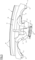
- Vehicle 1 shown on the Figure 1 comprises a passenger compartment 3, a windshield 5 and a dashboard 7 housed in the passenger compartment 3.
- the motor vehicle is a car.
- the motor vehicle is a truck, or a bus, or a utility vehicle, or a train, or any other motor vehicle.
- the longitudinal direction corresponds to the normal direction of movement of the motor vehicle.
- the vertical direction is perpendicular to the rolling plane of the vehicle, and the transverse direction is perpendicular to both the longitudinal direction and the vertical direction.
- front and back we mean in relation to the longitudinal direction.
- top and bottom we mean in relation to the vertical direction.
- right and left we mean in relation to the transverse direction.
- the windshield 5 is the window delimiting the passenger compartment 3 towards the front.
- Passenger compartment 3 is the interior space of the vehicle where the passengers are accommodated.
- the dashboard 7 is arranged at the front of the passenger compartment 3, below the windshield 5. It extends transversely from one side of the passenger compartment 3 to the other.
- the dashboard 7 comprises a supporting structure 9, a first deformable structure 11 and a second deformable structure 13.
- the supporting structure 9 is a relatively rigid structure, giving its structural rigidity to the dashboard 7.
- the supporting structure 9 is a thin structure, of complex shape.
- the supporting structure 9 is generally a thin shell, made of plastic material.
- the supporting structure 9 has a significant thickness, between 1 and 10 millimeters, preferably between 1 and 5 millimeters, more preferably between 1.5 and 2.5 millimeters.
- the plastic material is for example polypropylene (PP), or polyethylene (PE), or polycarbonate (PC) or even polystyrene (PS).
- the plastic material is advantageously reinforced with fibers, for example with natural fibers (hemp, wood, etc.) or glass.
- the supporting structure 9 is made of glass fiber reinforced polypropylene, obtained by injection, and having a thickness of 2.5 millimeters.
- the supporting structure 9 is made of a mixture of thermoformed polyethylene and polystyrene, and has a thickness of approximately 1.5 millimeters.
- the supporting structure 9 has a first large face 15 and a second large face 17 opposite the first large face 15.
- the first and second large faces 15, 17 are the two opposite faces of the shell constituting the supporting structure.
- the first large face 15 faces upwards. It faces towards the windshield 5.
- the second large face 17 faces downwards. It faces the floor of passenger compartment 3.
- the first deformable structure 11 is fixed to the supporting structure 9. It is fixed only to the supporting structure 9, in the sense that it has no attachment to an element of the dashboard or the vehicle other than the supporting structure 9. Thus, all the forces applied to the first deformable structure 11 are taken up by the supporting structure 9.
- the first deformable structure 11 is a deformable shell, made of plastic material.
- the first deformable structure 11 is obtained by thermoforming, by expansion or by injection of the plastic material.
- the first deformable structure 11 is made of a deformable material.
- the first deformable structure 11 is made of a material that deforms without creating a crack or rupture zone in the event of interference with another structure of the dashboard or the vehicle. Such interference generally occurs during the assembly of the various components of the dashboard, or during the mounting of the dashboard on board the vehicle. It may happen that during assembly or mounting, the first deformable structure comes to rest, temporarily or permanently, against another structure, and is therefore deformed. This deformation does not cause irreparable damage to the first deformable structure 11, because the latter is made of a deformable material.
- the first deformable structure 11 is for this purpose made of a plastic material with a thickness of less than 2 millimeters, for example between 0.1 and 1 millimeter, and even more preferably between 0.4 and 0.7 mm. It has for example a thickness of 0.5 millimeters.
- the plastic material is PE, or PP, or a mixture of PE and PP.
- the plastic material is unexpanded, and is solid, for example made by plastic injection.
- the first deformable structure 11 is of complex shape.
- the first deformable structure 11 delimits at least one first conduit 19, 21, 23, 25 having an open side 27 ( Figure 1 ).
- the open side 27 of the or each first conduit 19, 21, 23, 25 is closed by the first large face 15 of the supporting structure 9.
- the first deformable structure 11 delimits several first conduits referenced 19, 21, 23, 25, the functions of which will be described below.
- the or each first conduit 19, 21, 23, 25 has a complex shape, generally not rectilinear.
- the or each first conduit 19, 21, 23, 25 has an elongated shape, and extends along a central line C ( Figure 2 ). This centerline C extends along a three-dimensional path in the examples shown.
- the open side 27 extends substantially over the entire length of the first conduit 19, 21, 23, 25, the length being taken along the central line C.
- the open side 27 is located laterally with respect to the central line C.
- the or each first conduit 19, 21, 23, 25 is open over a part of its periphery, this periphery being considered around the central line C.
- the open side 27 covers, around the central line C, an angular sector generally between 30° and 180°, preferably between 45° and 135°, more preferably between 60° and 120°.
- This open side 27 is sealed by the first large face 15.
- the first deformable structure 11 is placed directly against the first large face 15 of the supporting structure 9.
- welds are, for example, mirror welds.
- Mirror welding is a thermal welding technique for joining thermoplastics, using a tool capable of heating from two sides at the same time.
- the tool is inserted between the two structures to be welded together, here the supporting structure 9 and the first deformable structure 11. After the structures are heated, the structures are pressed against each other.
- the first deformable structure 11 is thus fixed to the supporting structure 9, and more precisely to the first large face 15, by two weld lines 29 for each first conduit 19, 21, 23, 25. These weld lines 29 extend along and on either side of the open side 27. The weld lines 29 extend over the entire length of the or each first conduit 19, 21, 23, 25, the length being understood here as being the extent of the first conduit along the central line C. The weld lines 29 join at their ends to form a closed contour, or join only at one of the two ends, or alternatively do not join. Alternatively, the first deformable structure 11 is fixed to the supporting structure 9, by separate weld points and or a portion.
- the second deformable structure 13 is of the same type as the first deformable structure 11.
- the second deformable structure 13 is a thin shell, made of plastic material.
- the second deformable structure 13 is obtained by injection, by expansion or by thermoforming of the plastic material.
- the second deformable structure 13 is made of a deformable material.
- the second deformable structure 13 is made of a plastic material with a thickness of less than 2 millimeters, preferably between 0.1 and 1 millimeter, more preferably between 0.4 and 0.7 mm. It has, for example, a thickness of 0.5 millimeters.
- the plastic material is PE, or PP, or a mixture of PE and PP.
- the plastic material is unexpanded, and is completely made for example by plastic injection.
- the second deformable structure 13 is fixed to the supporting structure 9. It is fixed only to the supporting structure 9, in the sense that it does not have any point of attachment to another member of the dashboard or the vehicle. All forces applied to the second deformable structure 13 are absorbed by the supporting structure 9.
- the second deformable structure 13 delimits at least one second conduit 31, 33 having an open side 35.
- the open side 35 of the or each first conduit 31, 33 is closed by the first large face 17 of the supporting structure 9.
- the second deformable structure 13 delimits two second conduits 31, 33 whose functions will be described below.
- the or each second conduit 31, 33 has a complex shape, and has an elongated shape along a central line C'.
- This central line C' generally has a three-dimensional arrangement.
- the open side 35 extends over the entire length of the or each second conduit 31, 33, this length being taken along the central line C'. It extends laterally with respect to the central line C'.
- the or each second conduit 31, 33 is open over a part of its circumference, this circumference being taken around the central line C'.
- the open side 35 covers, around the central line C', an angular sector between 30° and 180°, preferably between 45° and 135°, and even more preferably between 60° and 120°.
- the second deformable structure 13 is directly fixed to the supporting structure 9, and more precisely to the second large face 17.
- these welds are generally mirror welds.
- the open side 35 of the or each second conduit 31, 33 is sealed by the second large face 17.
- the second deformable structure 13 is fixed to the supporting structure 9 by weld lines 39 which extend on either side of the or each open side 35.
- the weld lines 39 extend over the entire length of the or each second conduit 31, 33, this length being taken along the central line C'.
- the second deformable structure 113 is fixed to the supporting structure 9, by separate weld points and or a portion.
- the weld lines 39 join at both ends of the or each second conduit 31, 33, thus forming a line with a closed contour. Alternatively, they join at only one end as shown in the Figure 2 , or they do not meet.
- first deformable structure 11 is pressed against the first large face 15, and the second deformable structure 13 is pressed against the second large face 17.
- the first deformable structure 11 is thus located above the supporting structure 9, and the second deformable structure 13 is placed under the supporting structure 9.
- the motor vehicle 1 comprises an air conditioning device 41.
- This air conditioning device 41 comprises an air conditioning unit 43, connected by an upstream conduit 45 to an air inlet 47 opening out of the vehicle.
- the air conditioning unit 43 is designed to control the temperature of the air blown by the conditioning device 41 inside the passenger compartment 3.
- It comprises at least one heater, designed to heat the air drawn in through the air inlet 47. It also generally comprises a cooler, configured to cool the air drawn in through the air inlet 47.
- the at least one first conduit 19, 21, 23, 25 and the at least one second conduit 31, 33 are integrated into the air conditioning device 41.
- At least one first duct belongs to a defrosting circuit 48, and comprises orifices 49 intended to blow air towards the windshield windows 5 and/or door.
- At least one second duct belongs to an air conditioning circuit 51 of the passenger compartment 3 and supplies air to the orifices 53 arranged to blow air into the atmosphere of the passenger compartment.
- the orifices 53 may be equipped with a vent intended to control the directionality of the air flow.
- one of the first ducts namely the first duct 19, is integrated into the defrosting circuit 48.
- the other first ducts here the first ducts 21, 23 and 25, are integrated into the air conditioning circuit 51 of the passenger compartment.
- the second ducts 31, 33 are all integrated into the air conditioning circuit 51 of the passenger compartment.
- the passenger compartment air conditioning circuit 51 has the sole function of regulating the air temperature inside the passenger compartment 3, and does not have the function of defrosting the vehicle windows, or any other additional technical function.
- the air blowing orifices 53 supplied by the or each second duct 31, 33 open directly into a volume located at the rear of the dashboard. They open into the volume located between the dashboard 7 and the front seats of the vehicle.
- the passenger compartment air conditioning circuit 51 also includes other air blowing ports which will be described later.
- the air conditioning unit 43 has a first air conditioning outlet 55, fluidically connected to the first conduit 19. This connection is not shown in the figures.
- the supporting structure 9 comprises two air inlets 57 fluidly connected to the first duct 19.
- the air inlets 57 are orifices cut out in the supporting structure 9. They are fluidly connected to the first air-conditioned air outlet 55. They open directly into the first duct 19.
- the first duct 19 extends transversely over most of the transverse width of the dashboard. It has a slightly arched central line C, running along the windshield 5.
- the air conditioning unit 43 further comprises a second air conditioning outlet 59, fluidically connected to the air conditioning circuit 51 of the passenger compartment.
- the air outlet 59 may be equipped with a vent intended to control the directionality of the air flow.
- the supporting structure 9 comprises an air inlet 61 fluidly communicating with at least one second conduit 31, 33.
- the air inlet 61 is fluidically connected to the air-conditioned air outlet 59 by a conduit not shown. It consists of an orifice cut into the supporting structure 9.
- the first duct 25 directly supplies air to the air blowing orifices 63 opening into the atmosphere of the passenger compartment.
- the orifices 63 are placed in the center of the dashboard, while the orifices 53 are placed transversely to the left and right of the dashboard.
- the first conduit 25 fluidically connects the air inlet 61 to the air blowing orifices 63.
- the air inlet 61 does not open directly into the second conduits 31, 33.
- the second conduits 31, 33 are arranged transversely to the left and right of the dashboard.
- the supporting structure 9 has passage orifices 65, cut out in this structure.
- the second conduit 31 connects one of the passage orifices 65 to one of the blowing orifices 53.
- the other second conduit 33 connects the other passage orifice 65 to the other blowing orifice 53.
- first conduits 21 and 23 are arranged so as to place the first conduit 25 in fluid communication with the two orifices 65.
- first ducts 25 and 21 and the second duct 33 together define an air duct, the first ducts 21 and 25 defining an upstream section of the air duct and the second duct 33 defining a downstream section of the air duct.
- first ducts 25 and 23 and the second duct 31 together define another ventilation duct.
- the first ducts 25 and 23 define an upstream section of the ventilation duct and the second duct 31 defines a downstream section of the ventilation duct.
- first deformable structure 11 contains portions other than those used to define the at least one first conduit 19, 21, 23, 25.
- the second deformable structure 13 comprises portions in addition to those defining the at least one second conduit 31, 33. These portions are for example intended to fix the second deformable structure 13 to the supporting structure 9.
- the dashboard comprises a trim 67 covering the supporting structure 9, the first deformable structure 11 and the second deformable structure 13.
- This trim 67 defines a surface 69 visible to the passengers of the vehicle.
- the trim 67 is generally called the dashboard cover. It conceals the functional parts of the dashboard, in particular the supporting structure 9, the first deformable structure 11 and the second deformable structure 13.
- the dashboard and vehicle described above have multiple advantages.
- the installation of the dashboard in the vehicle is particularly simple.
- first deformable structure and/or the second deformable structure are made of a deformable material, it is possible to tolerate interference between the first deformable structure and/or the second deformable structure and other elements of the dashboard or the vehicle.
- this makes the dashboard more compact. There is no need to maintain a minimum distance between the first deformable structure and/or the second deformable structure and the structures surrounding them. The risk of generating unwanted noise by vibrations propagating in the dashboard is also reduced.
- first deformable structure and/or the second deformable structure are made of a plastic material with a thickness of less than 2 millimeters and/or of a plastic foam, it is possible to easily obtain deformable structures.
- Attaching the first deformable structure and/or the second deformable structure to the supporting structure by welding is particularly practical.
- the design of the dashboard is particularly suitable for attachment by welding. It consists of several thin shells, attached to each other by weld lines that are particularly easy to obtain. The risk of generating scrap during welding is reduced.
- the dashboard has a trim covering the supporting structure, the first deformable structure and the second deformable structure and defining the surface visible to the passengers of the vehicle makes it easy to improve the appearance of the dashboard.
- At least one first duct and at least one second duct are in fluid communication with each other, and together form an air duct, at least one first duct defining an upstream section of the air duct and at least one second ... at least a second duct defining a downstream section of the air duct, it is possible to obtain air ducts of complex shapes in the dashboard.
- the supporting structure can have several air inlets, allowing the air circulation in the air ducts to be organized according to needs.
- At least one first duct belongs to a defrosting circuit and has air blowing ports towards the windshield
- at least one second duct belongs to a passenger compartment air conditioning circuit supplying air to ports blowing air into the atmosphere of the passenger compartment
- the dashboard and vehicle may have several variations.
- the supporting structure, the first deformable structure and the second deformable structure can have all kinds of shapes, different from the shapes shown in the figures.
- the first deformable structure may delimit a single first conduit or alternatively two first conduits, three first conduits or more than three first conduits as in the example shown.
- the second deformable structure may delimit a single second conduit, or two second conduits, or more than two second conduits.
- the defrost circuit comprises an air duct defined by a single first duct.
- the air duct of the defrost circuit may comprise several first ducts, or one or more first ducts arranged in series with one or more second ducts, or even comprise one or more second ducts.
- the air conditioning circuit of the passenger compartment comprises an air duct made of a single first duct, and two other air ducts made of a first duct and a second duct in series one behind the other.
- the passenger compartment air conditioning circuit comprises fewer or more than three air ducts.
- Each air duct is defined by only a first duct, or only a second duct, or even one or more first ducts arranged in series with one or more second ducts.
- the number of air inlet openings or air passage openings provided in the supporting structure may differ from what is shown in the figures. It depends on the design of the air ducts.
Landscapes
- Engineering & Computer Science (AREA)
- Mechanical Engineering (AREA)
- Physics & Mathematics (AREA)
- Thermal Sciences (AREA)
- Chemical & Material Sciences (AREA)
- Combustion & Propulsion (AREA)
- Transportation (AREA)
- Body Structure For Vehicles (AREA)
Applications Claiming Priority (1)
| Application Number | Priority Date | Filing Date | Title |
|---|---|---|---|
| FR2311178A FR3154083B1 (fr) | 2023-10-17 | 2023-10-17 | Tableau de bord et véhicule automobile comprenant un tel tableau de bord |
Publications (1)
| Publication Number | Publication Date |
|---|---|
| EP4541633A1 true EP4541633A1 (de) | 2025-04-23 |
Family
ID=89308624
Family Applications (1)
| Application Number | Title | Priority Date | Filing Date |
|---|---|---|---|
| EP24206839.3A Pending EP4541633A1 (de) | 2023-10-17 | 2024-10-16 | Instrumententafel und kraftfahrzeug mit einer solchen instrumententafel |
Country Status (2)
| Country | Link |
|---|---|
| EP (1) | EP4541633A1 (de) |
| FR (1) | FR3154083B1 (de) |
Citations (3)
| Publication number | Priority date | Publication date | Assignee | Title |
|---|---|---|---|---|
| FR2756514B1 (fr) * | 1996-12-04 | 2001-09-28 | Valeo Climatisation | Conduit d'air pour planche de bord de vehicule automobile |
| US20020017798A1 (en) * | 2000-05-23 | 2002-02-14 | Kazushi Shikata | Vehicular cockpit module assembly and assembling method |
| US20200247478A1 (en) * | 2019-02-05 | 2020-08-06 | GM Global Technology Operations LLC | Hvac instrument panel bracket |
-
2023
- 2023-10-17 FR FR2311178A patent/FR3154083B1/fr active Active
-
2024
- 2024-10-16 EP EP24206839.3A patent/EP4541633A1/de active Pending
Patent Citations (3)
| Publication number | Priority date | Publication date | Assignee | Title |
|---|---|---|---|---|
| FR2756514B1 (fr) * | 1996-12-04 | 2001-09-28 | Valeo Climatisation | Conduit d'air pour planche de bord de vehicule automobile |
| US20020017798A1 (en) * | 2000-05-23 | 2002-02-14 | Kazushi Shikata | Vehicular cockpit module assembly and assembling method |
| US20200247478A1 (en) * | 2019-02-05 | 2020-08-06 | GM Global Technology Operations LLC | Hvac instrument panel bracket |
Also Published As
| Publication number | Publication date |
|---|---|
| FR3154083B1 (fr) | 2025-10-17 |
| FR3154083A1 (fr) | 2025-04-18 |
Similar Documents
| Publication | Publication Date | Title |
|---|---|---|
| EP0868339B1 (de) | Armaturentafel | |
| EP0313420B1 (de) | Kraftfahrzeugfensterscheibe | |
| EP4541633A1 (de) | Instrumententafel und kraftfahrzeug mit einer solchen instrumententafel | |
| EP2697088B1 (de) | Vorrichtung zur luftleitung für die frontpartie eines kraftfahrzeugs | |
| FR2831489A1 (fr) | Procede pour realiser deux planches de bord utilisant deux structures aerauliques | |
| FR2872091A1 (fr) | Traverse de planche de bord | |
| EP0281457A1 (de) | Montageverfahren für eine Heizungs- und/oder Klimaanlage in einem Kraftfahrzeug und Montageeinheit für die Durchführung dieses Verfahrens | |
| EP1614563B1 (de) | Träger im Fahrzeuginnenraum für eine Luftversorgungseinrichtungeinheit einer Klima-Anlage. | |
| EP1893472B1 (de) | Luftverteilungskanal im passagierraum eines kraftfahrzeugs | |
| EP1470990B1 (de) | Armaturenbrett für Kraftfahrzeug | |
| FR2867740A1 (fr) | Toit de vehicule automobile et vehicule automobile comportant un tel toit | |
| FR3158683A1 (fr) | Mousse de garniture d’un rétroviseur à gousset de véhicule automobile | |
| EP1195316B1 (de) | Armaturenträger für Kraftfahrzeug, und Kraftfahrzeug mit derartigen Armaturenträger | |
| FR2863549A1 (fr) | Module de distribution d'un flux d'air en provenance d'une installation de ventilation, chauffage et/ou climatisation de vehicule automobile et dispositif structurant l'integrant | |
| EP1614562B1 (de) | Luftweg und -Verteilung einer Klima-Einheit in einem Kraftfahrzeug. | |
| FR2860483A1 (fr) | Element de faux plancher multifonctionnel | |
| EP2736749B1 (de) | Anti-recycling-trennwand eines kraftfahrzeugs | |
| EP2183149B1 (de) | Auskleidung für den heckspoiler eines motorfahrzeugs sowie motorfahrzeug mit mindestens einer solchen auskleidung | |
| EP3744606B1 (de) | Belüftungsvorrichtung für fahrzeug, die mindestens ein schallabsorptionselement umfasst, und entsprechendes fahrzeug | |
| FR2881393A1 (fr) | Traverse de planche de bord de vehicule automobile, ensemble comprenant une telle traverse, et procede de fabrication d'une telle traverse | |
| FR2886888A1 (fr) | Dispositif de distribution d'air dans l'habitacle d'un vehicule automobile | |
| FR2758783A1 (fr) | Ensemble de poste avant d'habitacle de vehicule automobile | |
| FR2721877A1 (fr) | Structure de recouvrement d'un module a sac gonflable implante dans un organe d'un vehicule automobile | |
| FR2936467A1 (fr) | Piece d'aspect et vehicule muni d'une telle piece | |
| FR2780000A1 (fr) | Planche de bord comprenant un conduit d'aeration integre et procede d'obtention |
Legal Events
| Date | Code | Title | Description |
|---|---|---|---|
| PUAI | Public reference made under article 153(3) epc to a published international application that has entered the european phase |
Free format text: ORIGINAL CODE: 0009012 |
|
| STAA | Information on the status of an ep patent application or granted ep patent |
Free format text: STATUS: THE APPLICATION HAS BEEN PUBLISHED |
|
| AK | Designated contracting states |
Kind code of ref document: A1 Designated state(s): AL AT BE BG CH CY CZ DE DK EE ES FI FR GB GR HR HU IE IS IT LI LT LU LV MC ME MK MT NL NO PL PT RO RS SE SI SK SM TR |
|
| STAA | Information on the status of an ep patent application or granted ep patent |
Free format text: STATUS: REQUEST FOR EXAMINATION WAS MADE |
|
| 17P | Request for examination filed |
Effective date: 20250924 |
|
| GRAP | Despatch of communication of intention to grant a patent |
Free format text: ORIGINAL CODE: EPIDOSNIGR1 |
|
| STAA | Information on the status of an ep patent application or granted ep patent |
Free format text: STATUS: GRANT OF PATENT IS INTENDED |
|
| INTG | Intention to grant announced |
Effective date: 20260320 |