EP4541672A2 - Systèmes et procédés de freinage hybrides - Google Patents
Systèmes et procédés de freinage hybrides Download PDFInfo
- Publication number
- EP4541672A2 EP4541672A2 EP25154264.3A EP25154264A EP4541672A2 EP 4541672 A2 EP4541672 A2 EP 4541672A2 EP 25154264 A EP25154264 A EP 25154264A EP 4541672 A2 EP4541672 A2 EP 4541672A2
- Authority
- EP
- European Patent Office
- Prior art keywords
- braking system
- flight
- braking
- processor
- hydraulic
- Prior art date
- Legal status (The legal status is an assumption and is not a legal conclusion. Google has not performed a legal analysis and makes no representation as to the accuracy of the status listed.)
- Pending
Links
Images



Classifications
-
- B—PERFORMING OPERATIONS; TRANSPORTING
- B60—VEHICLES IN GENERAL
- B60T—VEHICLE BRAKE CONTROL SYSTEMS OR PARTS THEREOF; BRAKE CONTROL SYSTEMS OR PARTS THEREOF, IN GENERAL; ARRANGEMENT OF BRAKING ELEMENTS ON VEHICLES IN GENERAL; PORTABLE DEVICES FOR PREVENTING UNWANTED MOVEMENT OF VEHICLES; VEHICLE MODIFICATIONS TO FACILITATE COOLING OF BRAKES
- B60T13/00—Transmitting braking action from initiating means to ultimate brake actuator with power assistance or drive; Brake systems incorporating such transmitting means, e.g. air-pressure brake systems
- B60T13/10—Transmitting braking action from initiating means to ultimate brake actuator with power assistance or drive; Brake systems incorporating such transmitting means, e.g. air-pressure brake systems with fluid assistance, drive, or release
- B60T13/66—Electrical control in fluid-pressure brake systems
- B60T13/662—Electrical control in fluid-pressure brake systems characterised by specified functions of the control system components
-
- B—PERFORMING OPERATIONS; TRANSPORTING
- B60—VEHICLES IN GENERAL
- B60T—VEHICLE BRAKE CONTROL SYSTEMS OR PARTS THEREOF; BRAKE CONTROL SYSTEMS OR PARTS THEREOF, IN GENERAL; ARRANGEMENT OF BRAKING ELEMENTS ON VEHICLES IN GENERAL; PORTABLE DEVICES FOR PREVENTING UNWANTED MOVEMENT OF VEHICLES; VEHICLE MODIFICATIONS TO FACILITATE COOLING OF BRAKES
- B60T8/00—Arrangements for adjusting wheel-braking force to meet varying vehicular or ground-surface conditions, e.g. limiting or varying distribution of braking force
- B60T8/17—Using electrical or electronic regulation means to control braking
- B60T8/1701—Braking or traction control means specially adapted for particular types of vehicles
- B60T8/1703—Braking or traction control means specially adapted for particular types of vehicles for aircrafts
-
- B—PERFORMING OPERATIONS; TRANSPORTING
- B60—VEHICLES IN GENERAL
- B60T—VEHICLE BRAKE CONTROL SYSTEMS OR PARTS THEREOF; BRAKE CONTROL SYSTEMS OR PARTS THEREOF, IN GENERAL; ARRANGEMENT OF BRAKING ELEMENTS ON VEHICLES IN GENERAL; PORTABLE DEVICES FOR PREVENTING UNWANTED MOVEMENT OF VEHICLES; VEHICLE MODIFICATIONS TO FACILITATE COOLING OF BRAKES
- B60T8/00—Arrangements for adjusting wheel-braking force to meet varying vehicular or ground-surface conditions, e.g. limiting or varying distribution of braking force
- B60T8/32—Arrangements for adjusting wheel-braking force to meet varying vehicular or ground-surface conditions, e.g. limiting or varying distribution of braking force responsive to a speed condition, e.g. acceleration or deceleration
- B60T8/321—Arrangements for adjusting wheel-braking force to meet varying vehicular or ground-surface conditions, e.g. limiting or varying distribution of braking force responsive to a speed condition, e.g. acceleration or deceleration deceleration
- B60T8/325—Systems specially adapted for aircraft
-
- B—PERFORMING OPERATIONS; TRANSPORTING
- B60—VEHICLES IN GENERAL
- B60T—VEHICLE BRAKE CONTROL SYSTEMS OR PARTS THEREOF; BRAKE CONTROL SYSTEMS OR PARTS THEREOF, IN GENERAL; ARRANGEMENT OF BRAKING ELEMENTS ON VEHICLES IN GENERAL; PORTABLE DEVICES FOR PREVENTING UNWANTED MOVEMENT OF VEHICLES; VEHICLE MODIFICATIONS TO FACILITATE COOLING OF BRAKES
- B60T8/00—Arrangements for adjusting wheel-braking force to meet varying vehicular or ground-surface conditions, e.g. limiting or varying distribution of braking force
- B60T8/32—Arrangements for adjusting wheel-braking force to meet varying vehicular or ground-surface conditions, e.g. limiting or varying distribution of braking force responsive to a speed condition, e.g. acceleration or deceleration
- B60T8/88—Arrangements for adjusting wheel-braking force to meet varying vehicular or ground-surface conditions, e.g. limiting or varying distribution of braking force responsive to a speed condition, e.g. acceleration or deceleration with failure responsive means, i.e. means for detecting and indicating faulty operation of the speed responsive control means
- B60T8/885—Arrangements for adjusting wheel-braking force to meet varying vehicular or ground-surface conditions, e.g. limiting or varying distribution of braking force responsive to a speed condition, e.g. acceleration or deceleration with failure responsive means, i.e. means for detecting and indicating faulty operation of the speed responsive control means using electrical circuitry
-
- B—PERFORMING OPERATIONS; TRANSPORTING
- B60—VEHICLES IN GENERAL
- B60T—VEHICLE BRAKE CONTROL SYSTEMS OR PARTS THEREOF; BRAKE CONTROL SYSTEMS OR PARTS THEREOF, IN GENERAL; ARRANGEMENT OF BRAKING ELEMENTS ON VEHICLES IN GENERAL; PORTABLE DEVICES FOR PREVENTING UNWANTED MOVEMENT OF VEHICLES; VEHICLE MODIFICATIONS TO FACILITATE COOLING OF BRAKES
- B60T8/00—Arrangements for adjusting wheel-braking force to meet varying vehicular or ground-surface conditions, e.g. limiting or varying distribution of braking force
- B60T8/32—Arrangements for adjusting wheel-braking force to meet varying vehicular or ground-surface conditions, e.g. limiting or varying distribution of braking force responsive to a speed condition, e.g. acceleration or deceleration
- B60T8/88—Arrangements for adjusting wheel-braking force to meet varying vehicular or ground-surface conditions, e.g. limiting or varying distribution of braking force responsive to a speed condition, e.g. acceleration or deceleration with failure responsive means, i.e. means for detecting and indicating faulty operation of the speed responsive control means
- B60T8/92—Arrangements for adjusting wheel-braking force to meet varying vehicular or ground-surface conditions, e.g. limiting or varying distribution of braking force responsive to a speed condition, e.g. acceleration or deceleration with failure responsive means, i.e. means for detecting and indicating faulty operation of the speed responsive control means automatically taking corrective action
-
- B—PERFORMING OPERATIONS; TRANSPORTING
- B64—AIRCRAFT; AVIATION; COSMONAUTICS
- B64C—AEROPLANES; HELICOPTERS
- B64C25/00—Alighting gear
- B64C25/32—Alighting gear characterised by elements which contact the ground or similar surface
- B64C25/42—Arrangement or adaptation of brakes
- B64C25/44—Actuating mechanisms
-
- B—PERFORMING OPERATIONS; TRANSPORTING
- B60—VEHICLES IN GENERAL
- B60T—VEHICLE BRAKE CONTROL SYSTEMS OR PARTS THEREOF; BRAKE CONTROL SYSTEMS OR PARTS THEREOF, IN GENERAL; ARRANGEMENT OF BRAKING ELEMENTS ON VEHICLES IN GENERAL; PORTABLE DEVICES FOR PREVENTING UNWANTED MOVEMENT OF VEHICLES; VEHICLE MODIFICATIONS TO FACILITATE COOLING OF BRAKES
- B60T17/00—Component parts, details, or accessories of power brake systems not covered by groups B60T8/00, B60T13/00 or B60T15/00, or presenting other characteristic features
- B60T17/18—Safety devices; Monitoring
- B60T17/22—Devices for monitoring or checking brake systems; Signal devices
- B60T17/221—Procedure or apparatus for checking or keeping in a correct functioning condition of brake systems
-
- B—PERFORMING OPERATIONS; TRANSPORTING
- B60—VEHICLES IN GENERAL
- B60T—VEHICLE BRAKE CONTROL SYSTEMS OR PARTS THEREOF; BRAKE CONTROL SYSTEMS OR PARTS THEREOF, IN GENERAL; ARRANGEMENT OF BRAKING ELEMENTS ON VEHICLES IN GENERAL; PORTABLE DEVICES FOR PREVENTING UNWANTED MOVEMENT OF VEHICLES; VEHICLE MODIFICATIONS TO FACILITATE COOLING OF BRAKES
- B60T2270/00—Further aspects of brake control systems not otherwise provided for
- B60T2270/40—Failsafe aspects of brake control systems
-
- B—PERFORMING OPERATIONS; TRANSPORTING
- B60—VEHICLES IN GENERAL
- B60T—VEHICLE BRAKE CONTROL SYSTEMS OR PARTS THEREOF; BRAKE CONTROL SYSTEMS OR PARTS THEREOF, IN GENERAL; ARRANGEMENT OF BRAKING ELEMENTS ON VEHICLES IN GENERAL; PORTABLE DEVICES FOR PREVENTING UNWANTED MOVEMENT OF VEHICLES; VEHICLE MODIFICATIONS TO FACILITATE COOLING OF BRAKES
- B60T2270/00—Further aspects of brake control systems not otherwise provided for
- B60T2270/40—Failsafe aspects of brake control systems
- B60T2270/402—Back-up
-
- B—PERFORMING OPERATIONS; TRANSPORTING
- B60—VEHICLES IN GENERAL
- B60T—VEHICLE BRAKE CONTROL SYSTEMS OR PARTS THEREOF; BRAKE CONTROL SYSTEMS OR PARTS THEREOF, IN GENERAL; ARRANGEMENT OF BRAKING ELEMENTS ON VEHICLES IN GENERAL; PORTABLE DEVICES FOR PREVENTING UNWANTED MOVEMENT OF VEHICLES; VEHICLE MODIFICATIONS TO FACILITATE COOLING OF BRAKES
- B60T2270/00—Further aspects of brake control systems not otherwise provided for
- B60T2270/40—Failsafe aspects of brake control systems
- B60T2270/406—Test-mode; Self-diagnosis
-
- B—PERFORMING OPERATIONS; TRANSPORTING
- B64—AIRCRAFT; AVIATION; COSMONAUTICS
- B64C—AEROPLANES; HELICOPTERS
- B64C25/00—Alighting gear
- B64C25/32—Alighting gear characterised by elements which contact the ground or similar surface
- B64C25/42—Arrangement or adaptation of brakes
-
- B—PERFORMING OPERATIONS; TRANSPORTING
- B64—AIRCRAFT; AVIATION; COSMONAUTICS
- B64D—EQUIPMENT FOR FITTING IN OR TO AIRCRAFT; FLIGHT SUITS; PARACHUTES; ARRANGEMENT OR MOUNTING OF POWER PLANTS OR PROPULSION TRANSMISSIONS IN AIRCRAFT
- B64D45/00—Aircraft indicators or protectors not otherwise provided for
- B64D2045/0085—Devices for aircraft health monitoring, e.g. monitoring flutter or vibration
Definitions
- the present disclosure relates to aircraft wheel and brake systems and, more particularly, to systems and methods for enhancing rejected take off response in aircraft wheel and brake systems.
- Aircraft typically utilize brake systems on wheels to slow or stop the aircraft during landings, taxiing and emergency situations, such as, for example, a rejected take off (RTO), which generally refers to engagement of a brake system during an aborted take off and involves high braking loads over a short time period, resulting in a rapid increase in the brake temperature.
- RTO rejected take off
- the brake systems generally employ a heat sink comprising a series of friction disks, sandwiched between a pressure plate and an end plate, that may be forced into sliding contact with one another during a brake application to slow or stop the aircraft.
- a typical hydraulic brake system may include, without limitation, a source of pressurized hydraulic fluid, a hydraulic actuator for exerting a force across the heat sink (e.g., across the pressure plate, the series of friction disks and the end plate), a valve for controlling a pressure level provided to the hydraulic actuator and a brake control unit for receiving inputs from a pilot and from various feedback mechanisms and for producing responsive outputs to the valve.
- a pressurized fluid is applied to the hydraulic actuator, which may comprise a piston configured to translate the pressure plate toward the end plate.
- a typical electric brake system includes various electromechanical counterparts to a hydraulic brake system, such as, for example, an electromechanical brake actuator (EBA) in place of the hydraulic actuator and a source of electric power in place of the source of pressurized hydraulic fluid.
- EBA electromechanical brake actuator
- a braking system for an aircraft is disclosed herein.
- the braking system may comprise: a brake assembly; a hydraulic braking subsystem having a hydraulic brake actuator configured to operate the brake assembly; an electric braking subsystem having an electric brake actuator configured to operate the brake assembly; a hydraulic brake control unit configured to operate the hydraulic braking subsystem; and an electric brake control unit configured to operate the electric braking subsystem, the electric brake control unit in operable communication with the hydraulic brake control unit, wherein the braking system is configured to: determine a primary braking system for a prior flight cycle; and activate the electric braking subsystem to be the primary braking system for a current flight cycle in response to determining the hydraulic braking subsystem was the primary braking system for the prior flight cycle.
- only the primary braking system is configured to operate the brake assembly for a flight cycle.
- the electric brake control unit and the hydraulic brake control unit are both configured to receive an indication that the braking system has been powered up prior to determining the primary braking system for the prior flight cycle.
- the primary braking system may be further configured to command the secondary braking system to take over braking controls in response to determining the failure of the primary braking system.
- An article of manufacture is disclosed herein.
- the article of manufacture may include a tangible, non-transitory computer-readable storage medium having instructions stored thereon that, in response to execution by a processor, cause the processor to perform operations comprising: determining, by the processor, a take off phase of a flight for an aircraft; activating, by the processor, a secondary braking system of a braking system for possible use during the take off phase of the flight, the secondary braking system configured to operate independently from a primary braking system; determining, by the processor, a rejected take off (RTO) phase of the flight; and commanding, by the processor, braking of a brake assembly by the primary braking system and the secondary braking system during the RTO phase of the flight.
- RTO rejected take off
- the primary braking system is a hydraulic braking system and the secondary braking system is an electric braking system.
- the primary braking system is an electric braking system and the secondary braking system is a hydraulic braking system.
- the operations further comprise determining, via the processor, a selected primary braking system for a prior flight during a powering up of the processor.
- the operations may further comprise selecting, via the processor, the primary braking system for the flight based on the selected primary braking system for the prior flight, the selected primary braking system for the prior flight being the secondary braking system for the flight.
- the article of manufacture may include a tangible, non-transitory computer-readable storage medium having instructions stored thereon that, in response to execution by a processor, cause the processor to perform operations comprising: determining, by the processor, a take off phase of a flight for an aircraft; activating, by the processor, a secondary braking system of a braking system for possible use during the take off phase of the flight, the secondary braking system configured to operate independently from a primary braking system; determining, by the processor, a rejected take off (RTO) phase of the flight; and commanding, by the processor, braking via the primary braking system only during the RTO phase of the flight.
- RTO rejected take off
- the primary braking system is an electric braking subsystem of the braking system or a hydraulic braking subsystem of the braking system
- the secondary braking system is the hydraulic braking subsystem in response to the electric braking subsystem being the primary braking system.
- references to "a,” “an” or “the” may include one or more than one and that reference to an item in the singular may also include the item in the plural. Further, all ranges may include upper and lower values and all ranges and ratio limits disclosed herein may be combined.
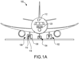
- the aircraft 100 further includes an avionics unit 112, which includes one or more controllers (e.g ., processors) and one or more tangible, non-transitory memories capable of implementing digital or programmatic logic.
- the one or more controllers are one or more of a general purpose processor, digital signal processor (DSP), application specific integrated circuit (ASIC), field programmable gate array (FPGA) or other programmable logic device, discrete gate, transistor logic, or discrete hardware component, or any of various combinations thereof or the like.
- the avionics unit 112 controls operation of various components of the aircraft 100.
- the BCUs 120 control various parameters of braking, such as manual brake control, automatic brake control, antiskid braking, locked wheel protection, touchdown protection, emergency/parking brake monitoring or gear retraction braking.
- the BCUs 120 may further include hardware 117 capable of performing various logic using discrete power signals received from various aircraft systems.
- the aircraft 100 further includes one or more brake assemblies coupled to each wheel assembly.
- a brake assembly 118 is coupled to the outer wheel assembly 110 of the third landing gear 106 of the aircraft 100. During operation, the brake assembly 118 applies a braking force to the outer wheel assembly 110 upon receiving a brake command from the BCUs 120.
- the outer wheel assembly 110 of the third landing gear 106 of the aircraft 100 (or of any of the other landing gear described above and herein) comprises any number of wheels or brake assemblies.
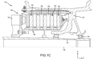
- the brake assembly 118 is mounted on an axle 130 for use with a wheel 132 disposed on and configured to rotate about the axle 130 via one or more bearing assemblies 134.
- a central axis 136 extends through the axle 130 and defines a center of rotation of the wheel 132.
- a torque plate barrel 138 (sometimes referred to as a torque tube or barrel or a torque plate) is aligned concentrically with the central axis 136, and the wheel 132 is rotatable relative to the torque plate barrel 138.
- the brake assembly 118 includes an actuator ram assembly 140, a pressure plate 142 disposed adjacent the actuator ram assembly 140, an end plate 144 positioned a distal location from the actuator ram assembly 140, and a plurality of rotor disks 146 interleaved with a plurality of stator disks 148 positioned intermediate the pressure plate 142 and the end plate 144.
- the pressure plate 142, the plurality of rotor disks 146, the plurality of stator disks 148 and the end plate 144 together form a brake heat sink or brake stack 150.
- the pressure plate 142, the end plate 144 and the plurality of stator disks 148 are mounted to the torque plate barrel 138 and remain rotationally stationary relative to the axle 130.
- the plurality of rotor disks 146 is mounted to the wheel 132 and rotate with respect to each of the pressure plate 142, the end plate 144 and the plurality of stator disks 148.
- An actuating mechanism for the brake assembly 118 includes a plurality of actuator ram assemblies, including the actuator ram assembly 140, circumferentially spaced around a piston housing 152 (only one actuator ram assembly is illustrated in FIG. 1C ).
- the plurality of actuator ram assemblies affects a braking action by urging the pressure plate 142 and the plurality of stator disks 148 into frictional engagement with the plurality of rotor disks 146 and against the end plate 144.
- the resulting frictional contact slows or stops or otherwise prevents rotation of the wheel 132.
- the plurality of rotor disks 146 and the plurality of stator disks 148 are fabricated from various materials, such as, for example, ceramic matrix composite materials, that enable the brake disks to withstand and dissipate the heat generated during and following a braking action.
- the actuator ram assemblies comprise a combination of electrically operated actuator rams (or electric brake actuators) and hydraulically operated actuator rams (or hydraulic brake actuators).
- a braking system 200 (or a redundant braking system or a hybrid braking system) is illustrated, in accordance with various embodiments.
- the braking system 200 may be separated into a hydraulic braking subsystem 202 and an electric braking subsystem 204.
- the braking system 200 includes a hydraulic brake control unit 220, which is programmed to control the various braking functions performed by the hydraulic braking subsystem 202.
- the hydraulic braking subsystem 202 includes a hydraulic power source 222 configured to provide a hydraulic fluid to a primary brake control module 224 via a primary hydraulic line 226.
- a primary pressure transducer 228 senses the pressure of the hydraulic fluid and provides a signal reflective of the pressure to the hydraulic brake control unit 220 via a data circuit 230.
- the hydraulic braking subsystem 202 includes a hydraulic fluid return 232 that is configured to return hydraulic fluid from the primary brake control module 224 to the hydraulic power source 222 via a return hydraulic line 234.
- a secondary hydraulic line 236 fluidly couples the primary brake control module 224 to a brake assembly 218, similar to the brake assembly 118 described above with reference to FIG. 1A . More particularly, the secondary hydraulic line 236 is fluidly coupled to a hydraulic brake actuator 217 (or a plurality of hydraulic brake actuators) housed within the brake assembly 218.
- a fuse 238 is fluidly coupled to the secondary hydraulic line 236 downstream of the primary brake control module 224.
- the fuse 238 acts as a shut-off valve or switch in the event the secondary hydraulic line 236 experiences a loss of pressure - e.g., in the event of a leak in the secondary hydraulic line 236 or the brake assembly 218 - thereby preventing hydraulic fluid from continuing to flow to the secondary hydraulic line 236 and leaking out of the hydraulic system.
- a secondary pressure transducer 240 is fluidly coupled to the secondary hydraulic line 236 and electrically coupled to the hydraulic brake control unit 220 via the data circuit 230.
- the hydraulic brake control unit 220 may, in redundant fashion, pass control of the braking system 200 to the electric braking subsystem 204.
- the secondary hydraulic line 236, the fuse 238, the secondary pressure transducer 240 and the brake assembly 218 are replicated for each of a plurality of outer wheel assemblies 210 and for each of a plurality of inner wheel assemblies 211 comprised within the braking system 200.
- the hydraulic braking subsystem 202 also includes wheel speed transducers and brake temperature sensors, such as, for example, an inboard wheel speed transducer 242 and an outboard wheel speed transducer 243, and an inboard brake temperature sensor 244 and an outboard brake temperature sensor 245.
- wheel speed transducers and brake temperature sensors such as, for example, an inboard wheel speed transducer 242 and an outboard wheel speed transducer 243, and an inboard brake temperature sensor 244 and an outboard brake temperature sensor 245.
- the braking system 200 includes an electric brake control unit 250, which is programmed to control the various braking functions performed by the electric braking subsystem 204.
- the electric braking subsystem 204 includes an electric power source 252 configured to provide electric power to an electric brake actuator controller 254, which, for example, may be an inboard electric brake actuator controller or an outboard electric brake actuator controller.
- the electric power is provided to the electric brake actuator controller 254 via an electric power circuit 257.
- the electric brake actuator controller 254 is electrically coupled to an electric brake actuator 219 (or a plurality of electric brake actuators) that is housed within the brake assembly 218.
- the electric brake actuator controller 254 includes or is connected to a control circuitry 256 configured to monitor various aspects of a braking operation.
- the electric brake actuator 219 may include, for example, a load cell 259 electrically coupled to the control circuitry 256 and configured to monitor the load applied via the electric brake actuator 219.
- the electric brake control unit 250 provides force commands to the electric brake controller 254, which in turn provides a current command to the electric brake actuator 219 to apply force, directing the electric brake actuator 219 to cause the brake assembly 218 to mechanically operate, thereby driving the brake assembly 218 to provide braking power.
- the brake actuator controller 254 monitors the load cell 259 (e.g., via the control circuitry 256) to apply more or less current to achieve a desired force.
- the electric brake actuator controller 254 is coupled to the electric brake control unit 250 via a communication link 258.
- the communication link 258 may comprise, for example, a controller area network bus 260.
- the electric braking subsystem 204 also includes wheel speed transducers, such as, for example, an inboard wheel speed transducer 262 and an outboard wheel speed transducer 263, or brake temperature sensors.
- the brake assembly 218 includes a pressure plate 215 configured to apply a compressive load against a brake stack or heat sink, which includes a plurality of brake rotors and a plurality of brake stators sandwiched between the pressure plate and an end plate.
- the brake assembly 218 includes the hydraulic brake actuator 217 (or a plurality of such hydraulic brake actuators) and the electric brake actuator 219 (or a plurality of such electric brake actuators).
- the brake assembly 218 includes four electric brake actuators spaced at ninety degree (90°) intervals about the pressure plate 215 and four hydraulic brake actuators spaced at ninety degree (90°) intervals about the pressure plate 215, with each electric brake actuator and each hydraulic brake actuator spaced at forty-five degree (45°) intervals. Fewer or greater numbers of actuators, both electric and hydraulic, are contemplated within the scope of the disclosure.
- a pilot or a co-pilot depresses a pilot brake pedal 270 or a co-pilot brake pedal 272, each of which is connected to a hydraulic brake position sensor 274 and to an electric brake position sensor 276.
- the hydraulic brake position sensor 274 generates a signal reflective of the pedal position that is transmitted to the hydraulic brake control unit 220 via a hydraulic brake sensor bus 278.
- the hydraulic brake control unit 220 if employed, then activates the hydraulic brake actuator 217 based on a current signal that is transmitted to the primary brake control module 224 via a primary brake control bus 225.
- an avionics system 282 is configured to employ one or both of the hydraulic braking subsystem 202 and the electric braking subsystem 204 via signals transmitted over a respective data bus 283.
- an autobrake selector 284 is configured to employ one or both of the hydraulic braking subsystem 202 and the electric braking subsystem 204 via signals transmitted over an autobrake data bus 285.
- the braking system 200 may operate in a fully hydraulic mode, employing only the hydraulic braking subsystem 202, or in a fully electric mode, employing only the electric braking subsystem 204.
- the disclosure contemplates, in various embodiments, the hydraulic braking subsystem 202 being employed as the principal braking system, while the electric braking subsystem 204 is employed as a backup braking system in the event a failure occurs with the hydraulic braking subsystem 202.
- the disclosure also contemplates, in various embodiments, the electric braking subsystem 204 being employed as a parking brake when the aircraft is at rest.
- the hydraulic brake control unit 220 and the electric brake control unit 250 are configured to communicate with one another via an intercommunication bus 286.
- Such communication enables, for example, transfer of control from the hydraulic brake control unit 220 to the electric brake control unit 250 following a failure of the hydraulic braking subsystem 202.
- the hydraulic brake control unit 220 may communicate with the electric brake control unit 250 and transfer control of the braking system 200 to the electric brake control unit 250.
- the electric brake control unit 250 may communicate with the hydraulic brake control unit 220 and transfer control of the braking system 200 to the hydraulic brake control unit 220.
- a primary braking system and a secondary braking system may be determined for each flight cycle, as described further herein. Based on a failure to the primary braking system being detected, the BCUs 120 are configured to transfer control from the primary braking system to the secondary braking system.
- the above disclosure provides for a hybrid braking architecture.
- the architecture employs hydraulic power for normal braking and electric power for an alternate braking system or a parking brake system.
- the architecture provides a fully redundant braking system for normal pedal operated braking and for emergency braking.
- the piston housing e.g., the piston housing 152 referred to in FIG.
- 1C is modified to accept four hydraulic actuators and four electric actuators, spaced equally and alternating between one hydraulic actuator and one electric actuator; though any number of actuators is contemplated by the disclosure.
- the equal spacing of forty-five degrees (45°) between alternating hydraulic and electric brake actuators allows for uniform force application on the brake stack when the hydraulic system is active or the electric system is active.
- the architecture is operated using pedals in the cockpit. This allows seamless activity and minimum pilot effort when, for example, the emergency system is engaged.
- the architecture is transparent for actuation (e.g ., automated), although crew-alerting system (CAS) messages may be employed to inform the pilot that the emergency system (e.g ., the electric braking subsystem) has become active.
- the hydraulic and electric brake control units are in constant communication using, for example, controller area network (CAN) communication links, such that when the primary brake control unit (either the hydraulic or the electric brake control unit) detects a loss of braking or other fault, the alternate brake control unit (either the hydraulic or the electric brake control unit) may take over control and operate the braking.
- CAN controller area network
- a switch may also be provided in the cockpit to allow the pilot to manually switch from the one braking subsystem to the other - e.g., the hydraulic subsystem to the electric sub system - depending on the failure and any other issues or faults occurring with the power supplies or other aircraft system degradations.
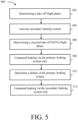
- the process 300 starts in response to the braking system 200 powering up (block 302). Once an aircraft 100 is parked at a gate, and a parking brake is set, aircraft engines, and the BCUs 120 may be powered down. Once the aircraft 100 is loaded with passengers and all maintenance checks have been performed, a pilot turns back on the BCUs 120 and the aircraft engines. In response to powering up the braking system 200 via the BCUs 120 (i.e., the hydraulic brake control unit 220 and the electric brake control unit 250), the process 300 is initiated.
- the BCUs 120 i.e., the hydraulic brake control unit 220 and the electric brake control unit 250
- the process 300 further comprises determining which brake subsystem (e.g., hydraulic braking subsystem 202 or electric braking subsystem 204) was active during a prior flight cycle (step 304).
- the BCUs 120 i.e., the hydraulic brake control unit 220 and the electric brake control unit 250
- store e.g., in the memory 116 the braking subsystem utilized in the previous flight cycle.
- the BCUs 120 determine if the previous active system was the hydraulic braking subsystem 202 in step 304.
- the BCUs 120 In response to determining the hydraulic braking subsystem 202 was utilized for the previous flight cycle, the BCUs 120 (e.g., via electric brake control unit 250) activate the electric braking subsystem 204 as a primary brake system for a current flight cycle (step 306). Similarly, in response to determining the electric braking subsystem 204 was utilized for the previous flight cycle, the BCUs 120 (e.g., via the hydraulic brake control unit 220) activate the hydraulic braking subsystem 202 for the current flight cycle (step 308). After selecting a primary brake system for sole use during the current flight cycle in step 306 or step 308, the process 300 ends at step 310.
- the process 300 keeps track of which system (e.g., hydraulic braking subsystem 202 or electric braking subsystem 204) was utilized for the previous flight cycle and alternates to the other subsystem for the following flight cycle.
- the process 300 facilitates exercise of both systems (e.g., hydraulic braking subsystem 202 or electric braking subsystem 204) frequently to avoid latent brake failures.
- the process 300 further allows use of the electric brake actuator 219 half of the time relative to conventional system, thus doubling the life of the electric braking subsystem 204.
- the process 400 comprises determining, via a primary BCU of the BCUs 120 (e.g., the electric brake control unit 250 or the hydraulic brake control unit 220, whichever is a primary brake control unit determined from process 300), an aircraft 100 is in a take off flight phase.
- the primary BCU may make this determination based on receiving sensor data (e.g., from a weight on wheel sensor, a speed sensor, etc.). For example, the primary BCU may receive data from a weight on wheel sensor indicating wheel 132 has weight on the wheel 132.
- the primary BCU is able to determine the aircraft is on the ground.
- an aircraft 100 has to reach an aircraft velocity to generate enough lift for the aircraft 100 to take off.
- the primary BCU is able to determine the aircraft 100 is in a take off flight phase.
- the speed threshold for determining a take off phase of flight may be approximately 70 knots.
- the present disclosure is not limited in this regard, and one skilled in the art may recognized various aircraft speed thresholds for determining a take off phase of flight, in accordance with various embodiments.
- the process 400 further comprises activating a secondary braking system in response to determining the aircraft 100 is in a take off phase of flight (step 404).
- a secondary braking system in response to determining the aircraft 100 is in a take off phase of flight.
- one of the hydraulic braking subsystem 202 or the electric braking subsystem 204 may be activated as a primary braking system for the flight cycle, and the remaining braking subsystem may be a secondary braking system for the flight cycle.
- the secondary braking system may be activated in case the take-off must be aborted.
- the process 400 further comprises determining a rejected take off (RTO) flight phase (step 406).
- a pilot may reduce an engine power provided to engines of the aircraft 100 to idle.
- the primary BCU may receive an indication that the engine power provided to the engines of the aircraft 100 have been reduced to idle, while the aircraft is in a take off phase (e.g., determined from step 402).
- the primary BCU may determine, based on a reduction of engine power to idle, that the aircraft 100 is in an RTO phase of flight.
- the process 400 further comprises commanding, via the primary BCU, the primary braking system and the secondary braking system to apply braking (step 408).
- the process 400 may facilitate a boost in braking to a maximum potential for the braking system 200 to stop the aircraft 100 as quickly as possible during the RTO phase of flight.
- references to "one embodiment,” “an embodiment,” “various embodiments,” etc. indicate that the embodiment described may include a particular feature, structure, or characteristic, but every embodiment may not necessarily include the particular feature, structure, or characteristic. Moreover, such phrases are not necessarily referring to the same embodiment. Further, when a particular feature, structure, or characteristic is described in connection with an embodiment, it is submitted that it is within the knowledge of one skilled in the art to affect such feature, structure, or characteristic in connection with other embodiments whether or not explicitly described. After reading the description, it will be apparent to one skilled in the relevant art(s) how to implement the disclosure in alternative embodiments.
- Numbers, percentages, or other values stated herein are intended to include that value, and also other values that are about or approximately equal to the stated value, as would be appreciated by one of ordinary skill in the art encompassed by various embodiments of the present disclosure.
- a stated value should therefore be interpreted broadly enough to encompass values that are at least close enough to the stated value to perform a desired function or achieve a desired result.
- the stated values include at least the variation to be expected in a suitable industrial process, and may include values that are within 10%, within 5%, within 1%, within 0.1%, or within 0.01% of a stated value. Additionally, the terms “substantially,” “about” or “approximately” as used herein represent an amount close to the stated amount that still performs a desired function or achieves a desired result.
- the term “substantially,” “about” or “approximately” may refer to an amount that is within 10% of, within 5% of, within 1% of, within 0.1% of, and within 0.01% of a stated amount or value.
- no element, component, or method step in the present disclosure is intended to be dedicated to the public regardless of whether the element, component, or method step is explicitly recited in the claims. No claim element herein is to be construed under the provisions of 35 U.S.C.
Landscapes
- Engineering & Computer Science (AREA)
- Mechanical Engineering (AREA)
- Transportation (AREA)
- Aviation & Aerospace Engineering (AREA)
- Valves And Accessory Devices For Braking Systems (AREA)
- Regulating Braking Force (AREA)
Applications Claiming Priority (2)
| Application Number | Priority Date | Filing Date | Title |
|---|---|---|---|
| US17/668,987 US11999468B2 (en) | 2022-02-10 | 2022-02-10 | Hybrid brake systems and methods |
| EP23153531.1A EP4227174B1 (fr) | 2022-02-10 | 2023-01-26 | Systèmes et procédés de freinage hybrides |
Related Parent Applications (2)
| Application Number | Title | Priority Date | Filing Date |
|---|---|---|---|
| EP23153531.1A Division-Into EP4227174B1 (fr) | 2022-02-10 | 2023-01-26 | Systèmes et procédés de freinage hybrides |
| EP23153531.1A Division EP4227174B1 (fr) | 2022-02-10 | 2023-01-26 | Systèmes et procédés de freinage hybrides |
Publications (2)
| Publication Number | Publication Date |
|---|---|
| EP4541672A2 true EP4541672A2 (fr) | 2025-04-23 |
| EP4541672A3 EP4541672A3 (fr) | 2025-07-02 |
Family
ID=85122483
Family Applications (2)
| Application Number | Title | Priority Date | Filing Date |
|---|---|---|---|
| EP23153531.1A Active EP4227174B1 (fr) | 2022-02-10 | 2023-01-26 | Systèmes et procédés de freinage hybrides |
| EP25154264.3A Pending EP4541672A3 (fr) | 2022-02-10 | 2023-01-26 | Systèmes et procédés de freinage hybrides |
Family Applications Before (1)
| Application Number | Title | Priority Date | Filing Date |
|---|---|---|---|
| EP23153531.1A Active EP4227174B1 (fr) | 2022-02-10 | 2023-01-26 | Systèmes et procédés de freinage hybrides |
Country Status (2)
| Country | Link |
|---|---|
| US (1) | US11999468B2 (fr) |
| EP (2) | EP4227174B1 (fr) |
Families Citing this family (5)
| Publication number | Priority date | Publication date | Assignee | Title |
|---|---|---|---|---|
| US12179912B2 (en) | 2020-09-29 | 2024-12-31 | Goodrich Corporation | Hybrid brake system |
| US12486050B2 (en) * | 2022-02-10 | 2025-12-02 | Goodrich Corporation | Hybrid brake systems and methods |
| US11970263B2 (en) | 2022-02-10 | 2024-04-30 | Goodrich Corporation | Hybrid brake systems and methods for load cell calibration |
| US11999468B2 (en) * | 2022-02-10 | 2024-06-04 | Goodrich Corporation | Hybrid brake systems and methods |
| US12403874B2 (en) * | 2022-06-23 | 2025-09-02 | Goodrich Corporation | Pedal processing for primary / alternate aircraft braking system architecture |
Family Cites Families (49)
| Publication number | Priority date | Publication date | Assignee | Title |
|---|---|---|---|---|
| US2888101A (en) | 1956-04-02 | 1959-05-26 | Bendix Aviat Corp | Applying system for disk brake |
| US4043607A (en) | 1975-02-07 | 1977-08-23 | Societe Nationale Industrielle Aerospatiale | Method and device for controlling disc brakes |
| EP0247253A1 (fr) | 1986-05-20 | 1987-12-02 | Landaire Dynabrake, Inc. | Système de freinage |
| FR2662647B1 (fr) | 1990-05-31 | 1995-06-09 | Bendix Europ Services Tech | Ensemble de freinage a amplification hydraulique. |
| WO1996026091A1 (fr) | 1995-02-22 | 1996-08-29 | Bosch Braking Systems Corporation | Systeme de freins de stationnement hydraulique et electrique |
| US6003640A (en) | 1997-05-09 | 1999-12-21 | The B.F. Goodrich Company | Electronic braking system with brake wear measurement and running clearance adjustment |
| WO1999026822A1 (fr) | 1997-11-22 | 1999-06-03 | Continental Teves Ag & Co. Ohg | Systeme de freinage electromecanique |
| GB2344178B (en) | 1998-11-27 | 2003-03-26 | Lucas Ind Plc | Detection and identification of pressure-sensor faults in electro-hydraulic (EHB) braking systems |
| US6530625B2 (en) | 1999-08-27 | 2003-03-11 | Alliedsignal Inc. | Electrically actuated brake with vibration damping |
| WO2003011668A1 (fr) | 2001-07-31 | 2003-02-13 | Continental Teves Ag & Co. Ohg | Procede permettant de determiner la relation entre la position d'un actionneur et la force de tension de cet actionneur |
| JP4700010B2 (ja) | 2004-10-29 | 2011-06-15 | 日立オートモティブシステムズ株式会社 | ブレーキ装置およびその制御装置 |
| EP1954538B1 (fr) | 2005-11-30 | 2014-05-21 | Goodrich Corporation | Unité de commande pour un système de freinage électromécanique à ajustement du jeu fonctionnel et procédé correspondant |
| US9085285B2 (en) | 2006-01-19 | 2015-07-21 | Hydro-Aire, Inc. | System and method for aircraft brake metering to alleviate structural loading |
| US7614340B2 (en) | 2007-02-09 | 2009-11-10 | Honeywell International Inc. | Composite piston housing for aircraft brakes |
| US8634971B2 (en) | 2009-05-05 | 2014-01-21 | Goodrich Corporation | Brake wear control system |
| US9227608B2 (en) | 2009-08-12 | 2016-01-05 | Meggitt Aircraft Braking Systems | Decentralized electric brake system |
| FR2954752B1 (fr) | 2009-12-24 | 2012-03-09 | Messier Bugatti | Ensemble de roue et frein pour aeronef equipe d'un dispositif d'entrainement en rotation. |
| US9228916B2 (en) | 2012-04-13 | 2016-01-05 | The Regents Of The University Of California | Self calibrating micro-fabricated load cells |
| FR2990413B1 (fr) | 2012-05-10 | 2014-06-06 | Messier Bugatti Dowty | Frein pour roue d'aeronef |
| FR2992288B1 (fr) | 2012-06-25 | 2015-03-06 | Messier Bugatti Dowty | Procede de deblocage d'un frein de roue d'aeronef |
| US9061674B2 (en) | 2012-10-24 | 2015-06-23 | Goodrich Corporation | Braking system and method of detecting a failure of a brake actuator |
| US9254913B2 (en) | 2013-11-05 | 2016-02-09 | Goodrich Corporation | Hybrid braking system and apparatus |
| GB2520696A (en) | 2013-11-27 | 2015-06-03 | Airbus Operations Ltd | Aircraft electric braking system |
| US20160001753A1 (en) | 2014-07-07 | 2016-01-07 | Goodrich Corporation | Apparatus and system for power distribution to brake systems |
| US9829402B2 (en) | 2015-02-03 | 2017-11-28 | Goodrich Corporation | Actuator system with smart load cell |
| CN104859626B (zh) | 2015-05-28 | 2017-07-14 | 西北工业大学 | 一种飞机电静液刹车作动器 |
| US9434369B1 (en) | 2015-06-24 | 2016-09-06 | Goodrich Corporation | Systems and methods for detecting an uncommanded brake overdrive condition |
| US10458497B2 (en) | 2015-06-29 | 2019-10-29 | Goodrich Corporation | Hybrid electric and hydraulic brake system |
| US9783171B2 (en) | 2015-07-02 | 2017-10-10 | Goodrich Corporation | Electromechanical braking systems and methods with power demand control |
| US10427665B2 (en) | 2016-03-21 | 2019-10-01 | Simmonds Precision Products, Inc. | Force feedback fault detection and accommodation for a multi-channel electric brake actuator controller |
| US9919795B2 (en) | 2016-03-21 | 2018-03-20 | Goodrich Corporation | Adaptive pressure skid control |
| US10300896B2 (en) | 2016-10-10 | 2019-05-28 | Textron Innovations, Inc. | Brake system for aircraft |
| US10435005B2 (en) | 2017-05-31 | 2019-10-08 | Simmonds Precision Products, Inc. | Electro-mechanical braking monitoring systems and methods |
| US10131329B1 (en) * | 2017-06-23 | 2018-11-20 | Goodrich, Corporation | Brake system power arbitration |
| US10543909B2 (en) | 2017-09-11 | 2020-01-28 | Goodrich Corporation | System and method for aircraft electric taxi brake optimization |
| US10752230B2 (en) | 2018-01-30 | 2020-08-25 | Goodrich Corporation | Prognostics for pressure sensors of hydraulic brake systems |
| GB2571100A (en) | 2018-02-15 | 2019-08-21 | Airbus Operations Ltd | Controller for an aircraft braking system |
| GB2571359A (en) | 2018-02-27 | 2019-08-28 | Airbus Operations Ltd | Brake monitoring |
| JP7056301B2 (ja) | 2018-03-26 | 2022-04-19 | 株式会社アドヴィックス | 制動制御装置 |
| US10493963B2 (en) | 2018-04-24 | 2019-12-03 | Goodrich Corporation | Mixed position and pressure control for hydraulic brake control applications |
| CN109027064B (zh) | 2018-07-17 | 2019-12-06 | 长沙学院 | 一种电气控制的制动装置 |
| JP2020050205A (ja) | 2018-09-27 | 2020-04-02 | 株式会社アドヴィックス | ブレーキ制御装置 |
| US10800387B1 (en) | 2019-03-29 | 2020-10-13 | Goodrich Corporation | Retractable electronic wear pin |
| GB2583486A (en) | 2019-04-29 | 2020-11-04 | Airbus Operations Ltd | Brake characteristics |
| FR3109250B1 (fr) | 2020-04-09 | 2022-10-14 | Foundation Brakes France | Procédé de commande d’un frein de véhicule automobile |
| US12179912B2 (en) * | 2020-09-29 | 2024-12-31 | Goodrich Corporation | Hybrid brake system |
| US12486050B2 (en) * | 2022-02-10 | 2025-12-02 | Goodrich Corporation | Hybrid brake systems and methods |
| US11999468B2 (en) * | 2022-02-10 | 2024-06-04 | Goodrich Corporation | Hybrid brake systems and methods |
| US11970263B2 (en) * | 2022-02-10 | 2024-04-30 | Goodrich Corporation | Hybrid brake systems and methods for load cell calibration |
-
2022
- 2022-02-10 US US17/668,987 patent/US11999468B2/en active Active
-
2023
- 2023-01-26 EP EP23153531.1A patent/EP4227174B1/fr active Active
- 2023-01-26 EP EP25154264.3A patent/EP4541672A3/fr active Pending
Also Published As
| Publication number | Publication date |
|---|---|
| EP4227174B1 (fr) | 2025-07-09 |
| EP4227174A2 (fr) | 2023-08-16 |
| EP4541672A3 (fr) | 2025-07-02 |
| EP4227174A3 (fr) | 2023-09-27 |
| US11999468B2 (en) | 2024-06-04 |
| US20230249808A1 (en) | 2023-08-10 |
Similar Documents
| Publication | Publication Date | Title |
|---|---|---|
| US11999468B2 (en) | Hybrid brake systems and methods | |
| US12486050B2 (en) | Hybrid brake systems and methods | |
| US12179912B2 (en) | Hybrid brake system | |
| EP3659877B1 (fr) | Système et procédé de détection d'une défaillance des freins par moyen du freinage pendant la rétraction du train d'atterrissage | |
| US11970263B2 (en) | Hybrid brake systems and methods for load cell calibration | |
| EP3418144B1 (fr) | Médiation de puissanced'un système de freinage | |
| EP4180287B1 (fr) | Système et procédé de surveillance de l'état des freins | |
| US11639160B2 (en) | Electrical power connection in an emergency park brake system | |
| US10053068B2 (en) | Systems and methods for brake control | |
| EP3909818B1 (fr) | Détection de défaillance de frein à l'aide de la vitesse des roues pendant la rétraction du train d'atterrissage | |
| EP4331928B1 (fr) | Système et procédé pour traiter une application de frein non commandée (ucb) et une détection de température de frein à l'aide d'une architecture primaire et alternative | |
| US11932222B2 (en) | Systems and methods for low speed braking operation | |
| CN114919737A (zh) | 飞行器及其制动控制系统、起落架和进行制动的方法 | |
| KR102200977B1 (ko) | 브레이크 제어전력 상실에 따른 항공기 착륙 사고 방지를 위한 항공기용 전자식 브레이크 시스템 | |
| US20230159011A1 (en) | Feel adjustment braking systems and methods | |
| EP4375186B1 (fr) | Systèmes et procédés de surveillance de l'état de santé pour servovalves | |
| US20240367626A1 (en) | Rdpc for primary secondary architecture |
Legal Events
| Date | Code | Title | Description |
|---|---|---|---|
| PUAI | Public reference made under article 153(3) epc to a published international application that has entered the european phase |
Free format text: ORIGINAL CODE: 0009012 |
|
| STAA | Information on the status of an ep patent application or granted ep patent |
Free format text: STATUS: THE APPLICATION HAS BEEN PUBLISHED |
|
| AC | Divisional application: reference to earlier application |
Ref document number: 4227174 Country of ref document: EP Kind code of ref document: P |
|
| AK | Designated contracting states |
Kind code of ref document: A2 Designated state(s): AL AT BE BG CH CY CZ DE DK EE ES FI FR GB GR HR HU IE IS IT LI LT LU LV MC ME MK MT NL NO PL PT RO RS SE SI SK SM TR |
|
| PUAL | Search report despatched |
Free format text: ORIGINAL CODE: 0009013 |
|
| AK | Designated contracting states |
Kind code of ref document: A3 Designated state(s): AL AT BE BG CH CY CZ DE DK EE ES FI FR GB GR HR HU IE IS IT LI LT LU LV MC ME MK MT NL NO PL PT RO RS SE SI SK SM TR |
|
| RIC1 | Information provided on ipc code assigned before grant |
Ipc: B60T 13/66 20060101ALI20250526BHEP Ipc: B60T 8/17 20060101AFI20250526BHEP |
|
| STAA | Information on the status of an ep patent application or granted ep patent |
Free format text: STATUS: REQUEST FOR EXAMINATION WAS MADE |
|
| 17P | Request for examination filed |
Effective date: 20251222 |