EP4541676A1 - Procédé de stabilisation d'un véhicule lors d'une situation de démarrage à partir de l'arrêt - Google Patents
Procédé de stabilisation d'un véhicule lors d'une situation de démarrage à partir de l'arrêt Download PDFInfo
- Publication number
- EP4541676A1 EP4541676A1 EP24202288.7A EP24202288A EP4541676A1 EP 4541676 A1 EP4541676 A1 EP 4541676A1 EP 24202288 A EP24202288 A EP 24202288A EP 4541676 A1 EP4541676 A1 EP 4541676A1
- Authority
- EP
- European Patent Office
- Prior art keywords
- vehicle
- signal
- brake
- drive
- deviation
- Prior art date
- Legal status (The legal status is an assumption and is not a legal conclusion. Google has not performed a legal analysis and makes no representation as to the accuracy of the status listed.)
- Pending
Links
Images
Classifications
-
- B—PERFORMING OPERATIONS; TRANSPORTING
- B60—VEHICLES IN GENERAL
- B60W—CONJOINT CONTROL OF VEHICLE SUB-UNITS OF DIFFERENT TYPE OR DIFFERENT FUNCTION; CONTROL SYSTEMS SPECIALLY ADAPTED FOR HYBRID VEHICLES; ROAD VEHICLE DRIVE CONTROL SYSTEMS FOR PURPOSES NOT RELATED TO THE CONTROL OF A PARTICULAR SUB-UNIT
- B60W30/00—Purposes of road vehicle drive control systems not related to the control of a particular sub-unit, e.g. of systems using conjoint control of vehicle sub-units
- B60W30/02—Control of vehicle driving stability
-
- B—PERFORMING OPERATIONS; TRANSPORTING
- B60—VEHICLES IN GENERAL
- B60W—CONJOINT CONTROL OF VEHICLE SUB-UNITS OF DIFFERENT TYPE OR DIFFERENT FUNCTION; CONTROL SYSTEMS SPECIALLY ADAPTED FOR HYBRID VEHICLES; ROAD VEHICLE DRIVE CONTROL SYSTEMS FOR PURPOSES NOT RELATED TO THE CONTROL OF A PARTICULAR SUB-UNIT
- B60W30/00—Purposes of road vehicle drive control systems not related to the control of a particular sub-unit, e.g. of systems using conjoint control of vehicle sub-units
- B60W30/18—Propelling the vehicle
- B60W30/18009—Propelling the vehicle related to particular drive situations
- B60W30/18027—Drive off, accelerating from standstill
-
- B—PERFORMING OPERATIONS; TRANSPORTING
- B60—VEHICLES IN GENERAL
- B60W—CONJOINT CONTROL OF VEHICLE SUB-UNITS OF DIFFERENT TYPE OR DIFFERENT FUNCTION; CONTROL SYSTEMS SPECIALLY ADAPTED FOR HYBRID VEHICLES; ROAD VEHICLE DRIVE CONTROL SYSTEMS FOR PURPOSES NOT RELATED TO THE CONTROL OF A PARTICULAR SUB-UNIT
- B60W10/00—Conjoint control of vehicle sub-units of different type or different function
- B60W10/04—Conjoint control of vehicle sub-units of different type or different function including control of propulsion units
-
- B—PERFORMING OPERATIONS; TRANSPORTING
- B60—VEHICLES IN GENERAL
- B60W—CONJOINT CONTROL OF VEHICLE SUB-UNITS OF DIFFERENT TYPE OR DIFFERENT FUNCTION; CONTROL SYSTEMS SPECIALLY ADAPTED FOR HYBRID VEHICLES; ROAD VEHICLE DRIVE CONTROL SYSTEMS FOR PURPOSES NOT RELATED TO THE CONTROL OF A PARTICULAR SUB-UNIT
- B60W40/00—Estimation or calculation of non-directly measurable driving parameters for road vehicle drive control systems not related to the control of a particular sub unit, e.g. by using mathematical models
- B60W40/10—Estimation or calculation of non-directly measurable driving parameters for road vehicle drive control systems not related to the control of a particular sub unit, e.g. by using mathematical models related to vehicle motion
- B60W40/114—Yaw movement
-
- B—PERFORMING OPERATIONS; TRANSPORTING
- B60—VEHICLES IN GENERAL
- B60W—CONJOINT CONTROL OF VEHICLE SUB-UNITS OF DIFFERENT TYPE OR DIFFERENT FUNCTION; CONTROL SYSTEMS SPECIALLY ADAPTED FOR HYBRID VEHICLES; ROAD VEHICLE DRIVE CONTROL SYSTEMS FOR PURPOSES NOT RELATED TO THE CONTROL OF A PARTICULAR SUB-UNIT
- B60W50/00—Details of control systems for road vehicle drive control not related to the control of a particular sub-unit, e.g. process diagnostic or vehicle driver interfaces
-
- B—PERFORMING OPERATIONS; TRANSPORTING
- B60—VEHICLES IN GENERAL
- B60W—CONJOINT CONTROL OF VEHICLE SUB-UNITS OF DIFFERENT TYPE OR DIFFERENT FUNCTION; CONTROL SYSTEMS SPECIALLY ADAPTED FOR HYBRID VEHICLES; ROAD VEHICLE DRIVE CONTROL SYSTEMS FOR PURPOSES NOT RELATED TO THE CONTROL OF A PARTICULAR SUB-UNIT
- B60W50/00—Details of control systems for road vehicle drive control not related to the control of a particular sub-unit, e.g. process diagnostic or vehicle driver interfaces
- B60W2050/0001—Details of the control system
- B60W2050/0019—Control system elements or transfer functions
- B60W2050/0028—Mathematical models, e.g. for simulation
-
- B—PERFORMING OPERATIONS; TRANSPORTING
- B60—VEHICLES IN GENERAL
- B60W—CONJOINT CONTROL OF VEHICLE SUB-UNITS OF DIFFERENT TYPE OR DIFFERENT FUNCTION; CONTROL SYSTEMS SPECIALLY ADAPTED FOR HYBRID VEHICLES; ROAD VEHICLE DRIVE CONTROL SYSTEMS FOR PURPOSES NOT RELATED TO THE CONTROL OF A PARTICULAR SUB-UNIT
- B60W50/00—Details of control systems for road vehicle drive control not related to the control of a particular sub-unit, e.g. process diagnostic or vehicle driver interfaces
- B60W2050/0001—Details of the control system
- B60W2050/0019—Control system elements or transfer functions
- B60W2050/0028—Mathematical models, e.g. for simulation
- B60W2050/0031—Mathematical model of the vehicle
- B60W2050/0033—Single-track, 2D vehicle model, i.e. two-wheel bicycle model
-
- B—PERFORMING OPERATIONS; TRANSPORTING
- B60—VEHICLES IN GENERAL
- B60W—CONJOINT CONTROL OF VEHICLE SUB-UNITS OF DIFFERENT TYPE OR DIFFERENT FUNCTION; CONTROL SYSTEMS SPECIALLY ADAPTED FOR HYBRID VEHICLES; ROAD VEHICLE DRIVE CONTROL SYSTEMS FOR PURPOSES NOT RELATED TO THE CONTROL OF A PARTICULAR SUB-UNIT
- B60W2520/00—Input parameters relating to overall vehicle dynamics
- B60W2520/10—Longitudinal speed
-
- B—PERFORMING OPERATIONS; TRANSPORTING
- B60—VEHICLES IN GENERAL
- B60W—CONJOINT CONTROL OF VEHICLE SUB-UNITS OF DIFFERENT TYPE OR DIFFERENT FUNCTION; CONTROL SYSTEMS SPECIALLY ADAPTED FOR HYBRID VEHICLES; ROAD VEHICLE DRIVE CONTROL SYSTEMS FOR PURPOSES NOT RELATED TO THE CONTROL OF A PARTICULAR SUB-UNIT
- B60W2520/00—Input parameters relating to overall vehicle dynamics
- B60W2520/12—Lateral speed
-
- B—PERFORMING OPERATIONS; TRANSPORTING
- B60—VEHICLES IN GENERAL
- B60W—CONJOINT CONTROL OF VEHICLE SUB-UNITS OF DIFFERENT TYPE OR DIFFERENT FUNCTION; CONTROL SYSTEMS SPECIALLY ADAPTED FOR HYBRID VEHICLES; ROAD VEHICLE DRIVE CONTROL SYSTEMS FOR PURPOSES NOT RELATED TO THE CONTROL OF A PARTICULAR SUB-UNIT
- B60W2520/00—Input parameters relating to overall vehicle dynamics
- B60W2520/12—Lateral speed
- B60W2520/125—Lateral acceleration
-
- B—PERFORMING OPERATIONS; TRANSPORTING
- B60—VEHICLES IN GENERAL
- B60W—CONJOINT CONTROL OF VEHICLE SUB-UNITS OF DIFFERENT TYPE OR DIFFERENT FUNCTION; CONTROL SYSTEMS SPECIALLY ADAPTED FOR HYBRID VEHICLES; ROAD VEHICLE DRIVE CONTROL SYSTEMS FOR PURPOSES NOT RELATED TO THE CONTROL OF A PARTICULAR SUB-UNIT
- B60W2520/00—Input parameters relating to overall vehicle dynamics
- B60W2520/14—Yaw
-
- B—PERFORMING OPERATIONS; TRANSPORTING
- B60—VEHICLES IN GENERAL
- B60W—CONJOINT CONTROL OF VEHICLE SUB-UNITS OF DIFFERENT TYPE OR DIFFERENT FUNCTION; CONTROL SYSTEMS SPECIALLY ADAPTED FOR HYBRID VEHICLES; ROAD VEHICLE DRIVE CONTROL SYSTEMS FOR PURPOSES NOT RELATED TO THE CONTROL OF A PARTICULAR SUB-UNIT
- B60W2520/00—Input parameters relating to overall vehicle dynamics
- B60W2520/20—Sideslip angle
-
- B—PERFORMING OPERATIONS; TRANSPORTING
- B60—VEHICLES IN GENERAL
- B60W—CONJOINT CONTROL OF VEHICLE SUB-UNITS OF DIFFERENT TYPE OR DIFFERENT FUNCTION; CONTROL SYSTEMS SPECIALLY ADAPTED FOR HYBRID VEHICLES; ROAD VEHICLE DRIVE CONTROL SYSTEMS FOR PURPOSES NOT RELATED TO THE CONTROL OF A PARTICULAR SUB-UNIT
- B60W2520/00—Input parameters relating to overall vehicle dynamics
- B60W2520/28—Wheel speed
-
- B—PERFORMING OPERATIONS; TRANSPORTING
- B60—VEHICLES IN GENERAL
- B60W—CONJOINT CONTROL OF VEHICLE SUB-UNITS OF DIFFERENT TYPE OR DIFFERENT FUNCTION; CONTROL SYSTEMS SPECIALLY ADAPTED FOR HYBRID VEHICLES; ROAD VEHICLE DRIVE CONTROL SYSTEMS FOR PURPOSES NOT RELATED TO THE CONTROL OF A PARTICULAR SUB-UNIT
- B60W2540/00—Input parameters relating to occupants
- B60W2540/18—Steering angle
-
- B—PERFORMING OPERATIONS; TRANSPORTING
- B60—VEHICLES IN GENERAL
- B60W—CONJOINT CONTROL OF VEHICLE SUB-UNITS OF DIFFERENT TYPE OR DIFFERENT FUNCTION; CONTROL SYSTEMS SPECIALLY ADAPTED FOR HYBRID VEHICLES; ROAD VEHICLE DRIVE CONTROL SYSTEMS FOR PURPOSES NOT RELATED TO THE CONTROL OF A PARTICULAR SUB-UNIT
- B60W2710/00—Output or target parameters relating to a particular sub-units
- B60W2710/06—Combustion engines, Gas turbines
- B60W2710/0666—Engine torque
-
- B—PERFORMING OPERATIONS; TRANSPORTING
- B60—VEHICLES IN GENERAL
- B60W—CONJOINT CONTROL OF VEHICLE SUB-UNITS OF DIFFERENT TYPE OR DIFFERENT FUNCTION; CONTROL SYSTEMS SPECIALLY ADAPTED FOR HYBRID VEHICLES; ROAD VEHICLE DRIVE CONTROL SYSTEMS FOR PURPOSES NOT RELATED TO THE CONTROL OF A PARTICULAR SUB-UNIT
- B60W2710/00—Output or target parameters relating to a particular sub-units
- B60W2710/08—Electric propulsion units
- B60W2710/083—Torque
-
- B—PERFORMING OPERATIONS; TRANSPORTING
- B60—VEHICLES IN GENERAL
- B60W—CONJOINT CONTROL OF VEHICLE SUB-UNITS OF DIFFERENT TYPE OR DIFFERENT FUNCTION; CONTROL SYSTEMS SPECIALLY ADAPTED FOR HYBRID VEHICLES; ROAD VEHICLE DRIVE CONTROL SYSTEMS FOR PURPOSES NOT RELATED TO THE CONTROL OF A PARTICULAR SUB-UNIT
- B60W2720/00—Output or target parameters relating to overall vehicle dynamics
- B60W2720/12—Lateral speed
- B60W2720/125—Lateral acceleration
-
- B—PERFORMING OPERATIONS; TRANSPORTING
- B60—VEHICLES IN GENERAL
- B60W—CONJOINT CONTROL OF VEHICLE SUB-UNITS OF DIFFERENT TYPE OR DIFFERENT FUNCTION; CONTROL SYSTEMS SPECIALLY ADAPTED FOR HYBRID VEHICLES; ROAD VEHICLE DRIVE CONTROL SYSTEMS FOR PURPOSES NOT RELATED TO THE CONTROL OF A PARTICULAR SUB-UNIT
- B60W2720/00—Output or target parameters relating to overall vehicle dynamics
- B60W2720/14—Yaw
-
- B—PERFORMING OPERATIONS; TRANSPORTING
- B60—VEHICLES IN GENERAL
- B60W—CONJOINT CONTROL OF VEHICLE SUB-UNITS OF DIFFERENT TYPE OR DIFFERENT FUNCTION; CONTROL SYSTEMS SPECIALLY ADAPTED FOR HYBRID VEHICLES; ROAD VEHICLE DRIVE CONTROL SYSTEMS FOR PURPOSES NOT RELATED TO THE CONTROL OF A PARTICULAR SUB-UNIT
- B60W2720/00—Output or target parameters relating to overall vehicle dynamics
- B60W2720/20—Sideslip angle
-
- B—PERFORMING OPERATIONS; TRANSPORTING
- B60—VEHICLES IN GENERAL
- B60W—CONJOINT CONTROL OF VEHICLE SUB-UNITS OF DIFFERENT TYPE OR DIFFERENT FUNCTION; CONTROL SYSTEMS SPECIALLY ADAPTED FOR HYBRID VEHICLES; ROAD VEHICLE DRIVE CONTROL SYSTEMS FOR PURPOSES NOT RELATED TO THE CONTROL OF A PARTICULAR SUB-UNIT
- B60W2720/00—Output or target parameters relating to overall vehicle dynamics
- B60W2720/26—Wheel slip
-
- B—PERFORMING OPERATIONS; TRANSPORTING
- B60—VEHICLES IN GENERAL
- B60W—CONJOINT CONTROL OF VEHICLE SUB-UNITS OF DIFFERENT TYPE OR DIFFERENT FUNCTION; CONTROL SYSTEMS SPECIALLY ADAPTED FOR HYBRID VEHICLES; ROAD VEHICLE DRIVE CONTROL SYSTEMS FOR PURPOSES NOT RELATED TO THE CONTROL OF A PARTICULAR SUB-UNIT
- B60W30/00—Purposes of road vehicle drive control systems not related to the control of a particular sub-unit, e.g. of systems using conjoint control of vehicle sub-units
- B60W30/18—Propelling the vehicle
- B60W30/18172—Preventing, or responsive to skidding of wheels
Definitions
- the invention relates to a method for stabilizing a vehicle during a starting situation from a standstill, wherein the vehicle is driven by a prime mover which generates a drive torque at driven wheels during the starting process, according to claim 1. Furthermore, the invention also relates to a device for carrying out the method according to claim 15.
- the drive slip means that no or insufficient longitudinal force can be transferred between the driven wheels and the road surface to accelerate the vehicle as desired, and/or no or insufficient lateral force can be transferred between the driven wheels and the road surface. This can cause the vehicle to slide sideways, especially in the case of a lateral incline and/or a low road friction coefficient.
- ASR traction control systems
- Today's ESP systems (which can also be integrated into a braking system) will not intervene in such a situation because at the very low speeds prevailing in a starting situation, a lower activation speed threshold of the ESP has not yet been reached and/or initializations cannot yet be completed at a standstill and/or braking interventions on the non-driven front axle do not work as a countermeasure against oversteer.
- the driver controls the starting situation, they can detect a critical situation arising in terms of lateral dynamics during acceleration and ease off the accelerator. Countersteering, however, would not be successful, since the vehicle is essentially still stationary or moving at a very low speed during the starting situation.
- HAD Highly Autonomous Driving
- the invention is based on the object of specifying a method and a device that can prevent driving instability during a starting situation.
- the invention recognizes that in a starting situation with lateral dynamic instability, there is a need for greater lateral guidance force at the driven wheels of the vehicle. This is achieved by adapting and, in particular, by reducing the drive torque depending on the deviation between the actual vehicle behavior and the desired vehicle behavior with regard to lateral dynamic behavior.
- the method is preferably implemented in the form of an (additional) start-up stability function or is implemented as an (additional) start-up stability function in an electronic control system.
- This start-up stability function is preferably provided outside of or in addition to a conventional driving stability control system such as ESP and/or outside of or in addition to a conventional traction control system (ASR).
- ASR traction control system
- a detected actual vehicle yaw rate represents the actual vehicle behavior
- a target vehicle yaw rate represents the target vehicle behavior.
- the deviation is then formed, for example, by a difference between the target vehicle yaw rate and the actual vehicle yaw rate.
- the magnitude of this difference is determined.
- the vehicle speed (v) is detected by evaluating the rotational speed of at least one non-driven wheel.
- a predetermined value can be used as the vehicle target rotation rate.
- a detected actual lateral acceleration of the vehicle can determine the actual vehicle behavior and a particularly predetermined or determined target vehicle lateral acceleration represent the target vehicle behavior.
- the deviation is then formed, for example, by a difference between the target vehicle lateral acceleration and the actual vehicle lateral acceleration. Preferably, the magnitude of this difference is determined.
- the method can also detect the starting situation of the vehicle by evaluating the speed of at least one non-driven wheel.
- the starting situation of the vehicle is detected by determining that a vehicle speed detected by means of at least one sensor increases from zero to a (lower) vehicle limit speed.
- the drive torque generated by the prime mover is reduced depending on the deviation. Reducing the drive torque means that a lower or reduced drive torque is requested compared to a drive torque requested by the driver or autonomously. Furthermore, the greater the deviation, the more the drive torque generated by the prime mover during the start-up process can be reduced. If, for example, the deviation exceeds a limit, the drive torque generated by the prime mover is reduced. This limit can be fixed or dependent on a lower vehicle speed limit above which wheel speeds can be detected.
- the method can determine the traction slip at least during the starting situation and then the adaptation and in particular the reduction of the drive torque can be carried out by setting a maximum permissible traction slip for the driven wheels which is smaller than a target traction slip specified by a traction control system (ASR).
- ASR traction control system
- the adjustment and in particular the reduction of the drive torque can be carried out by (directly) controlling the drive machine to adjust and in particular to reduce the drive torque.
- the process can also trigger the starting situation by a driver of the vehicle or autonomously, in particular by an autopilot.
- the electronic control is integrated into an electronic brake control unit of a vehicle's brake system.
- the brake system can, in particular, be an electro-pneumatic brake system, in particular an electronically controlled brake system (EBS).
- EBS electronically controlled brake system
- the brake system can be a pneumatic, electro-pneumatic, hydraulic, electro-hydraulic, or electric brake system.
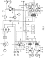
- FIG. 1 A preferred embodiment of a service brake system 1 of a towing vehicle of a towing vehicle-trailer combination is shown schematically.
- the towing vehicle-trailer combination has only a 2-axle semitrailer, but one or more drawbar trailers can also be attached to the towing vehicle.
- the service brake system 1 of the towing vehicle is formed, for example, by an electro-pneumatic friction brake system in the form of an electronically controlled brake system (EBS; Electronic Brake System).
- EBS electronically controlled brake system
- axle-wise or wheel-wise pressure control modules 16, 36, 38 are provided, with integrated inlet valves, outlet valves and backup valves as well as with pressure sensors for recording the actual brake pressure and with a higher-level control electronics for comparing the actual brake pressures with the target brake pressures according to the respective braking requirement.
- the electronically controlled braking system (EBS) of the towing vehicle further includes an anti-skid control system (ABS), whose ABS control routines are preferably integrated into a central brake control unit 14.
- ABS control routines of an anti-skid control system (ASR), an electronic stability program (ESP), and a starting stability function are preferably implemented in the central brake control unit 14 of the towing vehicle.
- the service brake system of the trailer is preferably also an electro-pneumatic brake system.
- the circuit diagram of the towing vehicle's electro-pneumatic service brake system 1 shown includes a foot brake signal sensor 2, a front axle reservoir 4 for supplying a front axle pressure circuit or front axle pressure channel, and a rear axle reservoir 6 for supplying a rear axle pressure circuit or rear axle pressure channel.
- the air supply, air conditioning, and protection are implemented, as required by law, by an air conditioning module 8 (not described in detail here).
- the rear axle reservoir pressure tank 6 is connected via pneumatic supply lines 10, 12 to a supply connection of a 2-channel pressure control module 16 for the brake cylinders 50 of the rear axle and to a rear axle foot brake valve 26 of the foot brake sensor 2.
- the front axle reservoir pressure tank 4 is connected via pneumatic supply lines 20, 22 to supply connections of two 1-channel pressure control modules 36, 38, each assigned to a brake cylinder 48 of a front wheel, and to a front axle foot brake valve 18 of the foot brake sensor 2.
- the foot brake value transmitter 2 therefore comprises two pneumatically acting foot brake valves 18, 26, which each generate a braking force depending on a braking request given by the driver’s foot on a brake pedal. generate pneumatic backup pressure or control pressure at the outputs of the foot brake valves 18, 26.
- an electrical front axle channel and an electrical rear axle channel are formed in the foot brake signal transmitter 2, combined in an electrical channel 28, which, depending on the braking request, each feed an electrical braking request signal into an electrical connection, preferably designed as a data bus 30, between the electrical channel 28 of the foot brake signal transmitter 2 and the central electronic brake control unit 14, which can differentiate between the two braking request signals for the front axle and the rear axle, for example due to load reasons.
- front axle foot brake valve 18 and the rear axle foot brake valve 26 of the foot brake signal transmitter 2 are each connected via a pneumatic control line 24, 32 to associated backup connections of the 2-channel pressure control module 16 and the 1-channel pressure control modules 36, 38, respectively.
- a pneumatic brake line 40, 42 leads from the working pressure connections of the 2-channel pressure control module 16 and the two 1-channel pressure control modules 36, 38, respectively, to the wheel-by-wheel brake cylinders 48, 50 of the front axle and the rear axle, respectively.
- Speed sensors 56 report the current speed of the rear wheels, which are driven here, for example, and the front wheels, which are not driven here, of the two-axle vehicle via electrical signal lines 58 to the central brake control unit 14.
- wear sensors 60 are preferably provided for each wheel brake, which report signals to the central brake control unit 14 via electrical signal lines 62 depending on the current brake wear.
- a trailer control module 64 is provided, which is connected on the one hand to a trailer pressure vessel 44 on the towing vehicle side via a The trailer control module 64 is supplied with compressed air via a supply line 46 and, on the other hand, is pneumatically controlled by backup pressure from the pneumatic control pressure, for example, of the front axle foot brake valve 18 of the foot brake signal transmitter 2 via a control line 52. Furthermore, the trailer control module 64 also receives an electrical signal from the central brake control unit 14 via an electrical control line 54. Finally, the trailer control module 64 is also controlled by a parking brake unit 66, which is not of interest here.
- the trailer control module 64 typically contains an inlet solenoid valve and an outlet solenoid valve, as well as a backup solenoid valve for pressure control of a relay valve, which is also integrated and supplied with compressed air from the trailer's compressed air supply 44.
- the relay valve and the relay valve control a control pressure for a "brake” coupling head 70.
- the relay valve modulates the control pressure for the "brake” coupling head 70 from the supply pressure of the trailer's supply pressure vessel 44 present at its supply connection, depending on the control pressure generated by the solenoid valves. This control pressure for the "brake” coupling head 70 is measured by an integrated pressure sensor and reported to the central brake control unit 14.
- the integrated backup valve switches through, and the relay valve is controlled by the pneumatic control pressure of the front axle brake circuit, which is carried in the control line 52.
- the trailer control module 64 passes the compressed air from the trailer compressed air supply 44 under supply pressure to a coupling head "supply" 68 of the towing vehicle.
- the brake application devices of the rear axle are preferably designed as known combination cylinders, i.e. as a combination of an active service brake cylinder 50 and a passive spring brake cylinder.
- Active means In this context, the service brake cylinders 50 apply when the brake is applied and release when the brake is released, and “passive” means that the spring-loaded brake cylinders apply when the brake is released and release when the brake is released.
- Passive means that the spring-loaded brake cylinders apply when the brake is released and release when the brake is released.
- the electro-pneumatic 2-channel pressure control module 16 designed as a structural unit, has two separately controllable pressure control channels. For each pressure control channel, a controlled working pressure applied to the respective working pressure ports for the brake cylinders 50 of the rear axle is generated based on a supply air source from the rear axle compressed air supply 6, depending on the brake request signal from the foot brake value transmitter 2. This controlled working pressure is measured by means of the integrated pressure sensors in order to adapt or adjust the measured actual brake pressure to the target brake pressure according to the brake request. In a similar manner, in each 1-channel pressure control module 36, 38 of the front axle, the brake pressure is individually controlled for the two brake cylinders 48 of the front axle wheels.
- each pressure control channel is therefore assigned its own compressed air supply 4, 6, wherein the pneumatic flow paths of each pressure control channel, starting from the assigned compressed air supply 4, 6 via the assigned pressure control modules 16, 36, 38 to the assigned brake application devices 48, 50, are designed to be pneumatically separated from the pneumatic flow path of a respective other pressure control channel.
- each pressure control module 16, 36, 38 is specially preferably assigned its own backup circuit, with its own backup valve for controlling a pneumatic backup or control pressure derived from the supply pressure of the compressed air supply 4, 6 assigned to the respective pressure control circuit of the rear axle or the front axle and formed by the foot brake value transmitter 2, from which the respective brake pressure at the working pressure connections of the pressure control modules 16, 36, 38 is formed in the event of a failure of electrical components.
- the braking system 1 of the towing vehicle and the braking system of the trailer are, as is usual with such braking systems, coupled to each other by means of a coupling head "supply” 68 and a coupling head “brake” 70.
- the electrical brake control signals from the central brake control unit 14 must be transmitted to the trailer via a CAN bus "trailer" 78 and an electronic trailer interface 76, since the trailer, for example, has an electro-pneumatic braking system.
- the trailer control module 64, as well as the 2-channel pressure control module 16 and the two 1-channel pressure control modules 36, 38, are each controlled by the central brake control unit 14 via an electrical control line 54, 88, 90, 92.
- the braking system functions as follows: During normal braking, the driver actuates the brake pedal and thus the foot brake signal transmitter 2, whereby an electrical brake request signal analogous to the desired target deceleration is generated in the electrical channel 28 and fed into the central brake control unit 14, which then controls the trailer control module 64, the 2-channel pressure control module 16, and the two 1-channel pressure control modules via the electrical control lines 54, 88, 90, 92 in accordance with the brake request signal and possibly depending on other parameters such as the respective load.
- the integrated inlet solenoid valves, outlet solenoid valves, and possibly backup solenoid valves which are usually designed as 2/2-way solenoid valves and are switched according to the braking request so that they pneumatically control the relay valves, which are also integrated, in order to control a target braking pressure or target control pressure corresponding to the braking request into the relevant brake cylinders 48, 50 of the towing vehicle and, on the trailer side, into the trailer control valve 80, which modulates the braking pressure for the trailer brake cylinders 84 from the target control pressure.
- the pressure sensors integrated in the pressure control modules 16, 36 and 38 and in the trailer control module 64 then report the actual braking pressure or actual control pressure to the central brake control unit 14, which then regulates the target braking pressure or target control pressure by controlling the module-side solenoid valves.
- the brake request signal for the central brake control unit 14 is generated autonomously by a driver assistance system such as ESP or ACC or by an autopilot instead of by the foot brake signal transmitter 2, the same functions as described above take place.
- the brake slip control or ABS of the towing vehicle is activated.
- the ABS routines implemented in the central brake control unit 14 adjust the brake pressures for the towing vehicle by appropriately controlling the solenoid valves in the pressure control module 36, 38 assigned to the respective wheel with brake slip or in the pressure control module 16 assigned to the respective wheels with brake slip, so that the brake slip control difference is compensated.
- Compatibility bands are stored in the central brake control unit 14, which determine the relationship between the desired braking z of the towing vehicle-trailer combination and the resulting braking force of the trailer or the pressure at the "brake" coupling head of the towing vehicle.
- the brake pressure for the trailer's braking system resulting from the compatibility band can then optionally be modified by coupling force control.
- the trailer control module 64 is then controlled by the central brake control unit 14 to adjust the pneumatic control pressure in the "brake" coupling head for the trailer according to these specifications.
- the brake pressure in the trailer would be determined depending on the brake pressure in the towing vehicle, which is influenced by the brake slip control.
- a device for stabilizing the towing vehicle during a start-up situation from a standstill is integrated here, for example, into the service brake system 1.
- the start-up stability function mentioned above is implemented as a program or program part in the central brake control unit 14.
- the device also includes the speed sensors 56 on the driven rear wheels and the non-driven front wheels and evaluates their speed signals, particularly during a start-up situation or during a start-up situation.
- the device also includes a sensor module 100, in which, for example, a yaw rate sensor and a lateral acceleration sensor are integrated.
- the sensor module 100 is signal-connected to the central brake control unit 14 in order, on the one hand, to be able to execute the ESP functions—as explained above—and, on the other hand, to supply yaw rate signals and lateral acceleration signals for the start-up stability function, which is implemented here, for example, in the central brake control unit 14.
- the central brake control unit 14 is signal-connected to an electronic drive control unit 110, for example, via a data bus.
- the electronic drive control unit 110 controls a drive motor of the towing vehicle, for example, an internal combustion engine and/or an electric motor, with respect to speed, drive torque and/or drive power.
- the prime mover drives the rear wheels, but not the front wheels of the towing vehicle.
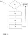
- the functioning of the start-up stability function is shown as a flow chart of a method 300 for stabilising the towing vehicle in a start-up situation from a standstill in Fig. 2
- the starting situation can be triggered by a driver of the towing vehicle or autonomously, in particular by an autopilot.
- a check is performed to determine whether the towing vehicle is in a starting situation, preferably by evaluating the speed signals from the speed sensors 56 on the non-driven front wheels. Based on these speed signals, the standstill and vehicle speed v of the towing vehicle can be detected.
- the starting situation is assumed to exist here, for example, if a driving speed v between zero and a lower vehicle speed limit, for example, between 3-5 km/h, is detected ("Y" for "Yes”). If no starting situation ("N" for "No") is detected, the process is aborted ("END").
- the actual vehicle behavior with respect to the lateral dynamics of the towing vehicle is determined in a subsequent step 302.
- the actual yaw rate signals received from the sensor module 100 are evaluated in the central brake control unit 14.
- a deviation of the actual vehicle behavior from a desired vehicle behavior with respect to the lateral dynamics of the vehicle is determined, here, for example, by determining a deviation of the actual rotation rate represented by the actual rotation rate signals from a desired rotation rate to be determined here.
- the deviation is, for example, formed by the difference between the desired rotation rate and the actual rotation rate.
- the magnitude of this difference is determined.
- the vehicle speed (v) is detected by evaluating the rotational speed of the non-driven front wheels.
- a predetermined value can be used as the target rotational speed.
- the actual lateral acceleration detected by the lateral acceleration sensor in the sensor module 100 can be evaluated in the central brake control unit 14 and compared with a target lateral acceleration.
- the deviation is then formed, for example, by a difference between the target lateral acceleration and the actual lateral acceleration.
- the absolute value of this difference is determined.
- the drive torque is adjusted depending on the deviation, in that the central brake control unit 14 directly controls the drive control unit, for example, in order to adjust the drive torque of the drive machine and in particular to reduce.
- the greater the deviation the more the drive torque generated by the prime mover during the start-up situation can be reduced.
- the drive torque generated by the prime mover during the start-up situation can only be reduced once the deviation has exceeded a limit. Reducing the drive torque increases lateral dynamic stability during the start-up situation because greater lateral guidance force is then available at the driven wheels of the towing vehicle.
Landscapes
- Engineering & Computer Science (AREA)
- Transportation (AREA)
- Mechanical Engineering (AREA)
- Automation & Control Theory (AREA)
- Chemical & Material Sciences (AREA)
- Combustion & Propulsion (AREA)
- Human Computer Interaction (AREA)
- Physics & Mathematics (AREA)
- Mathematical Physics (AREA)
- Regulating Braking Force (AREA)
Applications Claiming Priority (1)
| Application Number | Priority Date | Filing Date | Title |
|---|---|---|---|
| DE102023128836.9A DE102023128836A1 (de) | 2023-10-20 | 2023-10-20 | Verfahren zur Stabilisierung eines Fahrzeugs bei einer Anfahrsituation aus dem Stillstand |
Publications (1)
| Publication Number | Publication Date |
|---|---|
| EP4541676A1 true EP4541676A1 (fr) | 2025-04-23 |
Family
ID=92899911
Family Applications (1)
| Application Number | Title | Priority Date | Filing Date |
|---|---|---|---|
| EP24202288.7A Pending EP4541676A1 (fr) | 2023-10-20 | 2024-09-24 | Procédé de stabilisation d'un véhicule lors d'une situation de démarrage à partir de l'arrêt |
Country Status (4)
| Country | Link |
|---|---|
| US (1) | US20250128712A1 (fr) |
| EP (1) | EP4541676A1 (fr) |
| CN (1) | CN119858543A (fr) |
| DE (1) | DE102023128836A1 (fr) |
Citations (3)
| Publication number | Priority date | Publication date | Assignee | Title |
|---|---|---|---|---|
| US20100161188A1 (en) * | 2008-12-22 | 2010-06-24 | Gm Global Technology Operations, Inc. | System and method for performance launch control of a vehicle |
| EP1993867B1 (fr) * | 2006-02-15 | 2010-08-18 | Eaton Corporation | Commande de traction à stabilité améliorée au moyen d'un coupleur central commandé électriquement |
| US20200122534A1 (en) * | 2018-10-18 | 2020-04-23 | Ford Global Technologies, Llc | Systems and methods for tire warmup and vehicle launch optimization |
Family Cites Families (4)
| Publication number | Priority date | Publication date | Assignee | Title |
|---|---|---|---|---|
| US6704622B2 (en) * | 2001-12-28 | 2004-03-09 | Visteon Global Technologies, Inc. | Vehicle stability control |
| DE102005015062B4 (de) * | 2004-03-31 | 2020-09-03 | Continental Teves Ag & Co. Ohg | Verfahren zum Ermitteln eines Fahrzeugstillstands und Vorrichtung zum Unterstützen des Anfahrens eines Fahrzeugs bergaufwarts sowie Anfahrassistent |
| DE102007036578B4 (de) * | 2006-08-10 | 2023-05-25 | Continental Automotive Technologies GmbH | Verfahren und Vorrichtung zur robusteren Rutscherkennung von Fahrzeugen |
| DE102017201483A1 (de) * | 2017-01-31 | 2018-08-02 | Bayerische Motoren Werke Aktiengesellschaft | Verfahren zur Fahrdynamikregelung eines Kraftfahrzeugs sowie Fahrdynamikregelungssystem für ein Kraftfahrzeug |
-
2023
- 2023-10-20 DE DE102023128836.9A patent/DE102023128836A1/de active Pending
-
2024
- 2024-09-13 US US18/885,059 patent/US20250128712A1/en active Pending
- 2024-09-24 EP EP24202288.7A patent/EP4541676A1/fr active Pending
- 2024-10-18 CN CN202411456961.3A patent/CN119858543A/zh active Pending
Patent Citations (3)
| Publication number | Priority date | Publication date | Assignee | Title |
|---|---|---|---|---|
| EP1993867B1 (fr) * | 2006-02-15 | 2010-08-18 | Eaton Corporation | Commande de traction à stabilité améliorée au moyen d'un coupleur central commandé électriquement |
| US20100161188A1 (en) * | 2008-12-22 | 2010-06-24 | Gm Global Technology Operations, Inc. | System and method for performance launch control of a vehicle |
| US20200122534A1 (en) * | 2018-10-18 | 2020-04-23 | Ford Global Technologies, Llc | Systems and methods for tire warmup and vehicle launch optimization |
Also Published As
| Publication number | Publication date |
|---|---|
| US20250128712A1 (en) | 2025-04-24 |
| CN119858543A (zh) | 2025-04-22 |
| DE102023128836A1 (de) | 2025-04-24 |
Similar Documents
| Publication | Publication Date | Title |
|---|---|---|
| EP2994355B1 (fr) | Procédé de freinage d'un ensemble véhicule tracteur-remorque avec une force de freinage de remorque réduite en fonction de la réaction du système abs du véhicule tracteur | |
| EP3724043B1 (fr) | Équipement électrique d'un véhicule comprenant une régulation dynamique redondante de l'abs et de la dynamique de conduite | |
| DE102018002990B4 (de) | Hydraulische Kraftfahrzeug-Bremsanlage und Verfahren zum Betreiben derselben | |
| EP3576995B1 (fr) | Équipement électrique d'un véhicule comprenant un dispositif de freinage et de direction au moins partiellement électrique | |
| DE102014013756C5 (de) | Elektrische Ausrüstung eines Fahrzeugs mit einer wenigstens teilweise elektrischen Brems- und Lenkeinrichtung mit hoher Verfügbarkeit | |
| EP1016572B1 (fr) | Dispositif et procédé de stabilisation d'un attelage de véhicules constitué d'un tracteur et d'une remorque | |
| EP2776293B1 (fr) | Procédé et dispositif de régulation électronique de la répartition de la force de freinage en fonction du glissement différentiel | |
| EP3642089A1 (fr) | Équipement électrique pour un véhicule ou une combinaison de véhicules comprenant un véhicule tracteur et au moins un véhicule tracté | |
| WO2015104168A1 (fr) | Procédé de commande d'un dispositif de freinage d'un ensemble tracteur-remorque et dispositif de freinage commandé selon le procédé | |
| EP2244919A1 (fr) | Frein de stationnement pour véhicule, et procédé permettant de faire fonctionner ce frein de stationnement | |
| DE10137148A1 (de) | Bremsanlage für Nutzfahrzeuganhänger | |
| EP3322619A1 (fr) | Procédé et dispositif de régulation électronique d'un ralentissement d'un véhicule à régulation du glissement de freinage | |
| DE19545001B4 (de) | Verfahren zur Giermoment-Abschwächung bei einem Antiblockiersystem | |
| EP2419309B1 (fr) | Procédé de contrôle d'un véhicule dont seul l'essieu arrière est freiné et contrôleutr de glissement de freinage | |
| EP3256356B1 (fr) | Dispositif de frein de service électropneumatique d'un véhicule à réduction du bruit lors du relâchement du frein ainsi que son procédé de commande | |
| EP1131235A1 (fr) | Procede et dispositif de stabilisation d'un vehicule equipe d'un systeme de freinage antiblocage de roues | |
| EP4392299B1 (fr) | Procede d'operation d'un train de vehicules | |
| EP4288311B1 (fr) | Procédé pour faire fonctionner un système de commande d'un véhicule à fonction de freinage de direction et régulation antipatinage | |
| EP4541676A1 (fr) | Procédé de stabilisation d'un véhicule lors d'une situation de démarrage à partir de l'arrêt | |
| DE102017010867A1 (de) | Verfahren und Vorrichtung zum Steuern einer Bremsanlage eines Anhängers während einer Kurvenfahrt | |
| DE19640141A1 (de) | Schlupfgeregelte Druckluft-Bremsanlage für Nutzfahrzeuge | |
| EP1888383A1 (fr) | Procede et systeme de commande de conditions de roulage d'un vehicule terrestre |
Legal Events
| Date | Code | Title | Description |
|---|---|---|---|
| PUAI | Public reference made under article 153(3) epc to a published international application that has entered the european phase |
Free format text: ORIGINAL CODE: 0009012 |
|
| STAA | Information on the status of an ep patent application or granted ep patent |
Free format text: STATUS: THE APPLICATION HAS BEEN PUBLISHED |
|
| AK | Designated contracting states |
Kind code of ref document: A1 Designated state(s): AL AT BE BG CH CY CZ DE DK EE ES FI FR GB GR HR HU IE IS IT LI LT LU LV MC ME MK MT NL NO PL PT RO RS SE SI SK SM TR |
|
| STAA | Information on the status of an ep patent application or granted ep patent |
Free format text: STATUS: REQUEST FOR EXAMINATION WAS MADE |
|
| 17P | Request for examination filed |
Effective date: 20251023 |
|
| GRAP | Despatch of communication of intention to grant a patent |
Free format text: ORIGINAL CODE: EPIDOSNIGR1 |
|
| STAA | Information on the status of an ep patent application or granted ep patent |
Free format text: STATUS: GRANT OF PATENT IS INTENDED |
|
| RIC1 | Information provided on ipc code assigned before grant |
Ipc: B60W 30/02 20120101AFI20260128BHEP |
|
| INTG | Intention to grant announced |
Effective date: 20260206 |
|
| GRAS | Grant fee paid |
Free format text: ORIGINAL CODE: EPIDOSNIGR3 |
|
| GRAA | (expected) grant |
Free format text: ORIGINAL CODE: 0009210 |
|
| STAA | Information on the status of an ep patent application or granted ep patent |
Free format text: STATUS: THE PATENT HAS BEEN GRANTED |