EP4541981A1 - Erdbebensicheres dachsystem und verfahren zur herstellung von lasttragenden strukturen - Google Patents
Erdbebensicheres dachsystem und verfahren zur herstellung von lasttragenden strukturen Download PDFInfo
- Publication number
- EP4541981A1 EP4541981A1 EP24206981.3A EP24206981A EP4541981A1 EP 4541981 A1 EP4541981 A1 EP 4541981A1 EP 24206981 A EP24206981 A EP 24206981A EP 4541981 A1 EP4541981 A1 EP 4541981A1
- Authority
- EP
- European Patent Office
- Prior art keywords
- roofing
- battens
- transverse
- anchoring
- batten
- Prior art date
- Legal status (The legal status is an assumption and is not a legal conclusion. Google has not performed a legal analysis and makes no representation as to the accuracy of the status listed.)
- Granted
Links
Images


Classifications
-
- E—FIXED CONSTRUCTIONS
- E04—BUILDING
- E04D—ROOF COVERINGS; SKY-LIGHTS; GUTTERS; ROOF-WORKING TOOLS
- E04D13/00—Special arrangements or devices in connection with roof coverings; Protection against birds; Roof drainage ; Sky-lights
- E04D13/16—Insulating devices or arrangements in so far as the roof covering is concerned, e.g. characterised by the material or composition of the roof insulating material or its integration in the roof structure
- E04D13/1606—Insulation of the roof covering characterised by its integration in the roof structure
- E04D13/1612—Insulation of the roof covering characterised by its integration in the roof structure the roof structure comprising a supporting framework of roof purlins or rafters
-
- E—FIXED CONSTRUCTIONS
- E04—BUILDING
- E04B—GENERAL BUILDING CONSTRUCTIONS; WALLS, e.g. PARTITIONS; ROOFS; FLOORS; CEILINGS; INSULATION OR OTHER PROTECTION OF BUILDINGS
- E04B7/00—Roofs; Roof construction with regard to insulation
- E04B7/02—Roofs; Roof construction with regard to insulation with plane sloping surfaces, e.g. saddle roofs
- E04B7/022—Roofs; Roof construction with regard to insulation with plane sloping surfaces, e.g. saddle roofs consisting of a plurality of parallel similar trusses or portal frames
- E04B7/024—Roofs; Roof construction with regard to insulation with plane sloping surfaces, e.g. saddle roofs consisting of a plurality of parallel similar trusses or portal frames the trusses or frames supporting load-bearing purlins, e.g. braced purlins
-
- E—FIXED CONSTRUCTIONS
- E04—BUILDING
- E04B—GENERAL BUILDING CONSTRUCTIONS; WALLS, e.g. PARTITIONS; ROOFS; FLOORS; CEILINGS; INSULATION OR OTHER PROTECTION OF BUILDINGS
- E04B7/00—Roofs; Roof construction with regard to insulation
- E04B7/20—Roofs consisting of self-supporting slabs, e.g. able to be loaded
-
- E—FIXED CONSTRUCTIONS
- E04—BUILDING
- E04D—ROOF COVERINGS; SKY-LIGHTS; GUTTERS; ROOF-WORKING TOOLS
- E04D1/00—Roof covering by making use of tiles, slates, shingles, or other small roofing elements
- E04D1/34—Fastenings for attaching roof-covering elements to the supporting elements
-
- E—FIXED CONSTRUCTIONS
- E04—BUILDING
- E04D—ROOF COVERINGS; SKY-LIGHTS; GUTTERS; ROOF-WORKING TOOLS
- E04D13/00—Special arrangements or devices in connection with roof coverings; Protection against birds; Roof drainage ; Sky-lights
- E04D13/16—Insulating devices or arrangements in so far as the roof covering is concerned, e.g. characterised by the material or composition of the roof insulating material or its integration in the roof structure
- E04D13/1606—Insulation of the roof covering characterised by its integration in the roof structure
- E04D13/1612—Insulation of the roof covering characterised by its integration in the roof structure the roof structure comprising a supporting framework of roof purlins or rafters
- E04D13/1618—Insulation of the roof covering characterised by its integration in the roof structure the roof structure comprising a supporting framework of roof purlins or rafters with means for fixing the insulating material between the roof covering and the upper surface of the roof purlins or rafters
-
- E—FIXED CONSTRUCTIONS
- E04—BUILDING
- E04D—ROOF COVERINGS; SKY-LIGHTS; GUTTERS; ROOF-WORKING TOOLS
- E04D13/00—Special arrangements or devices in connection with roof coverings; Protection against birds; Roof drainage ; Sky-lights
- E04D13/16—Insulating devices or arrangements in so far as the roof covering is concerned, e.g. characterised by the material or composition of the roof insulating material or its integration in the roof structure
- E04D13/1606—Insulation of the roof covering characterised by its integration in the roof structure
- E04D13/1612—Insulation of the roof covering characterised by its integration in the roof structure the roof structure comprising a supporting framework of roof purlins or rafters
- E04D13/1637—Insulation of the roof covering characterised by its integration in the roof structure the roof structure comprising a supporting framework of roof purlins or rafters the roof purlins or rafters being mainly insulated from the interior, e.g. the insulating material being fixed under or suspended from the supporting framework
-
- E—FIXED CONSTRUCTIONS
- E04—BUILDING
- E04D—ROOF COVERINGS; SKY-LIGHTS; GUTTERS; ROOF-WORKING TOOLS
- E04D13/00—Special arrangements or devices in connection with roof coverings; Protection against birds; Roof drainage ; Sky-lights
- E04D13/17—Ventilation of roof coverings not otherwise provided for
- E04D13/172—Roof insulating material with provisions for or being arranged for permitting ventilation of the roof covering
-
- E—FIXED CONSTRUCTIONS
- E04—BUILDING
- E04D—ROOF COVERINGS; SKY-LIGHTS; GUTTERS; ROOF-WORKING TOOLS
- E04D12/00—Non-structural supports for roofing materials, e.g. battens, boards
- E04D12/004—Battens
- E04D12/006—Batten-supporting means
-
- E—FIXED CONSTRUCTIONS
- E04—BUILDING
- E04D—ROOF COVERINGS; SKY-LIGHTS; GUTTERS; ROOF-WORKING TOOLS
- E04D1/00—Roof covering by making use of tiles, slates, shingles, or other small roofing elements
- E04D1/34—Fastenings for attaching roof-covering elements to the supporting elements
- E04D2001/347—Fastenings for attaching roof-covering elements to the supporting elements characterised by the fastening pattern
Definitions
- a roofing system for covering an upper area of a building and a method of making a roofing system for covering an upper area of a building.
- This patent application relates to the technical field of construction engineering and nonstructural roofing (or roofing) systems for covering upper exterior areas of the load-bearing structures of a building, focusing in particular on the earthquake resistance of fastening systems for nonstructural roofing elements, such as the roofing membrane (generally composed of tiles).
- nonstructural roofing elements are commonly used for aesthetic and practical purposes in order to cover the load-bearing structure of a building with a roof top.
- a roofing system is known to form the roof of a building.
- the supporting structure may have an external upper area to be covered with different geometry, usually polygonal, or even a plurality of different upper areas, separated by architectural elements and/or arranged on different levels.
- Each upper area is covered by one or possibly a plurality of pitches of the roof system, each pitch comprising a plurality of superimposing functional layers.
- the last layer is generally the roofing membrane, consisting of tiles attached to one of the layers below.
- roof coverings that do not provide earthquake resistance are described in CH 702 527.0 , DE 35 15 419 and EP 1 582 649 that anchor the supporting battens of the shingles, but not the shingles themselves, which are only supported and therefore subject to uplift in the event of wind or seismic shaking.
- the technical problem arises of improving the earthquake resistance of the attachment of the nonstructural roofing elements, particularly the roofing membrane (shingles), in order to ensure that they remain anchored to the supporting structure during seismic events.
- the system be easy and inexpensive to manufacture and assemble and easily installed on load-bearing structures of buildings.
- An additional desirable aspect is that the system be adaptable for covering buildings with upper exterior areas having different geometries and extensions.
- a roofing system comprising one or more pitches for covering an upper exterior area of a load-bearing structure, the one or more pitches being extended in length parallel to a longitudinal direction and in width parallel to a transverse direction and comprising: a layer of insulation, comprising one or more panels of insulation material and a plurality of transverse battens, each rigidly joined to one of the panels and capable of being attached to the supporting structure by first fasteners so that the one or more panels are attached to the supporting structure; an ventilation layer, comprising a plurality of transverse ventilation battens, each superimposing in a vertical direction and attached to one of said insulation battens; a plurality of longitudinal anchor battens, arranged orthogonally above the ventilation battens at predetermined intervals in the transverse direction, the anchor battens attached to the transverse ventilation battens by fasteners, with at least one fastener arranged at each intersection between a transverse ventilation batten and a longitudinal anchor batten; a roofing membrane, comprising
- a subset of selected roofing elements is anchored to one of the longitudinal anchoring battens by a respective anchoring element, so as to anchor the roofing membrane to the underlying layer of anchoring battens; said subassembly includes at least all the perimeter roofing elements arranged along the lateral perimeter of the pitch roofing membrane, which are anchored to an underlying anchoring batten by a respective anchoring element, and starting from the second order inward rows and columns of the roofing membrane (140), the density of anchoring elements (142) is lower than that along the perimeter (144,145) of the roofing membrane (140).
- the invention pertains to a method of covering an upper exterior area of a load-bearing structure, in which on the upper exterior area to be covered, a covering pitch is formed, extended in length parallel to a longitudinal direction and in width parallel to a transverse direction, by the following steps:
- FIG. 1 schematically shows the load-bearing structure 1 of a building whose upper exterior surface includes two areas 2 sloping convergent and flanked along an upper perimeter line.
- a roof covering 10 comprises an example of the implementation of the roofing system according to the present invention, comprising two pitches 100 converging and flanking each other along a ridge line 3 at which the roof 10 is closed by a row of ridge tiles.
- Each stratum 100 covers an upper area 2 extended in a plane parallel to a transverse axis Y-Y in width and a longitudinal axis X-X in length; in the transverse direction Y-Y, the area 2 is extended between the upper perimeter line and a lower perimeter line 2b, while in the longitudinal direction X-X the area 2 is extended between opposite lateral perimeter lines 2a.
- pitches 100 are illustrated for covering areas 2 with rectangular shape, it is understood that the perimeter lines 2a,2b are not necessarily straight or parallel and that each area 2 to be covered may have different shape of the lateral perimeter, e.g. polygonal with four or more sides, with the perimeter lines including one or more of said sides.
- lateral retaining planks 5 may be arranged, attached to the supporting structure 1 and in the example extended parallel to the Y-Y transverse direction.
- the lower perimeter line 2b one or more starting planks 4 may be arranged.
- the upper perimeter line there may generally be a sub-ridge assembly supporting the ridge tiles 3.
- the sub- ridge assembly includes a longitudinal ridge-holding batten, and preferably all ridge caps 3 are attached to the ridge-holding batten by a respective ridge-holding hook.
- the end 3 ridge tiles of the ridge row are also preferably fastened to the sub-colm batten by appropriate wood screws.
- a roofing system 10 and a related method of realization for roofing an area 2 of the supporting structure 1 of a building to be covered with a roof will be illustrated below.
- a pitch 100 of the roof system of the present invention is itself extended in the longitudinal-transverse X-Y direction with a lateral perimeter, generally polygonal and having a shape corresponding or similar to the lateral perimeter of the area 2 to be covered.
- System 100 comprises a plurality of layers stacked along a vertical height direction, comprising: a vapor barrier layer 101 (optional), an insulation layer 110, a layer comprising transverse ventilation battens 120, a layer 130 of longitudinal anchoring battens, and a roofing membrane 140.
- the insulation layer 110 is interposed between the supporting structure 1 and the roofing membrane 140 and includes one or more panels 111 of suitable insulation material to thermally insulate the supporting structure from the external environment.
- a preferred material may, for example, be expanded polystyrene.
- six 111 panels are shown side by side in the longitudinal X-X direction.
- Each panel 111 has at least one batten 112 integrated or preassembled within it, extended in the Y-Y transverse direction between two opposite longitudinal sides 114 perimeter of panel 111.
- the battens 112 are specifically of wood material.
- the insulation layer 110 is attached to the supporting structure by a plurality of first fasteners 113, particularly comprising wood/cement fastening screws.
- first fasteners 113 are used for each transverse batten 112, arranged spaced apart in the transverse direction.
- a distance between fasteners 113 along the same batten is preferably a maximum of 120cm.
- each fastener 113 is arranged at a distance d2 less than or equal to 65cm, preferably about 60cm, from the longitudinal perimeter side 114 of the insulating layer 110 closest to it.
- a depth of penetration of the fasteners 113 into the supporting structure is preferably at least 3cm.
- the fasteners 113 allow optimal attachment of the roofing system to the supporting structure 1 even during seismic events.
- Fig. 2 Also shown schematically in Fig. 2 are the starting plank 4 and the side planks 5 that can be fixed at the perimeter sides of area 2 by respective structural screws arranged, for example, every 60cm.
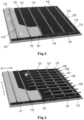
- Fig. 3 shows the fixing stage of ventilation layer 120 on insulation layer 110.
- the ventilation layer 120 comprises a plurality of transverse ventilation battens 121, each fixed on a respective batten 112 of the insulation layer.
- Each ventilation batten 121 is attached to an underlying batten 112 by a plurality of second fasteners 122, particularly wood-to-wood fastening screws.
- a transverse distance d3 of the first fastener 122 from the outer longitudinal side of the panel 111 is between 1/3-2/3 of d2, preferably 1 ⁇ 2 of d2. This particularly avoids damaging the insulation layer 110 batten with screws 113,122 that are too close together.
- a distance d4 between successive fasteners 122 along batten 121 is configured to avoid overlap with screws 113 below, and is preferably greater than d3 and d2, preferably equal to 90cm.
- the number of fasteners 122 is for each batten 121 preferably greater than the number of insulation-structure fasteners 113 of the underlying batten 112, preferably at least 3 fasteners per panel 111.
- a waterproofing sheathing 115 may be interposed between the insulation layer panels 110 and the ventilation battens 121.
- Fig. 4 shows the stage of fixing the layer of longitudinal 130 anchoring battens for the 140 roofing membrane.
- the longitudinal anchorage battens 130 are mounted orthogonal to the ventilation battens 121.
- a transverse distance D5 between third 131 fasteners mentioned above can be chosen based on a desired pitch between roofing shingles 140 and is generally less than the previous distances d2,d4 and greater than d3.
- Fig. 5 shows the roofing system 100 at a stage of laying and anchoring the roofing membrane 140.
- the roofing membrane 140 of a pitch comprises a plurality of roofing elements 141, generally in the form of tiles, arranged on longitudinal rows and transverse columns. Adjacent roofing elements in the transverse direction are partially superimposing so that the elements 141 of an upper row partially retain the elements 141 of the lower row toward the supporting structure 1.
- a subset of selected roofing elements 141 is anchored to the underlying layer of anchoring battens 130 by a respective anchoring element 142, which anchors the roofing element 141 to one of the longitudinal battens 130.
- each anchoring element may be a hook 142 with a head 142a configured for stable coupling to an edge of the roofing element 141 and an arm 142b extended from the head 142a toward the longitudinal batten 130 to which it is attached by means of a free fastening end.
- the arm 142b is L-shaped with a long side extended vertically from the head 142a and a short side conformed with said fastening end 142c.
- the roofing membrane 140 defines a lateral perimeter of the pitch 100, in the example having longitudinal sides 144 and transverse sides 145, which in the example substantially corresponds to the lateral perimeter of the area 2 to be covered.
- At least all of the perimeter 141 roofing elements arranged along the perimeter 144,145 of the pitch 100 of the roofing system, i.e., in the first top row, the first bottom row, and the first side columns, are anchored to an underlying anchor batten 130 by a respective attachment element 142.
- one or more of the perimeter roofing elements of stratum 100 may include an additional part of roofing element, which is cut to size and glued in an outer lateral position to a whole roofing element to form a single solid body.
- a single-component polyurethane adhesive for bonding e.g., the turret adhesive produced by BMI Group, which is a solvent-free single-component polyurethane adhesive that reacts by exposure to atmospheric moisture and has excellent water resistance (according to EN 204, D4) and good chemical resistance.
- the perimeter roofing element 141 consists of the whole element and the cut element glued together, and the anchoring element 142 is preferably attached to the whole element of the perimeter tile. From the second-order inward rows and columns of the roofing membrane 140, the anchor density 142 is preferably lower than that along the perimeter 144,145.
- the perimeter (141) roofing elements arranged along the perimeter (144,145) side of the pitch (100) roofing membrane and the roofing elements placed from the second order inward of rows and columns of the roofing membrane (140), equipped with a respective anchor element (142) are arranged in a diagonal crisscross pattern.
- the shingles 141 arranged in the innermost portion of the pitch of the fourth order of columns and the third order of rows may be substantially free of anchoring elements 142.
- the roofing system of the present invention allows for roofs that can withstand most seismic events without the roofing membrane being detached from the supporting structure.
- the special arrangement of the anchors and fasteners of the superimposing layers ensures both that the entire roofing system remains integral to the load-bearing structure and that the engaged roofing membrane is retained while still allowing the necessary flexibility of the anchorage for energy dissipation.
Landscapes
- Engineering & Computer Science (AREA)
- Architecture (AREA)
- Civil Engineering (AREA)
- Structural Engineering (AREA)
- Physics & Mathematics (AREA)
- Electromagnetism (AREA)
- Mechanical Engineering (AREA)
- Roof Covering Using Slabs Or Stiff Sheets (AREA)
Applications Claiming Priority (1)
| Application Number | Priority Date | Filing Date | Title |
|---|---|---|---|
| IT202300021678 | 2023-10-18 |
Publications (2)
| Publication Number | Publication Date |
|---|---|
| EP4541981A1 true EP4541981A1 (de) | 2025-04-23 |
| EP4541981B1 EP4541981B1 (de) | 2026-03-11 |
Family
ID=89897526
Family Applications (1)
| Application Number | Title | Priority Date | Filing Date |
|---|---|---|---|
| EP24206981.3A Active EP4541981B1 (de) | 2023-10-18 | 2024-10-16 | Erdbebensicheres dachsystem und verfahren zur herstellung von lasttragenden strukturen |
Country Status (1)
| Country | Link |
|---|---|
| EP (1) | EP4541981B1 (de) |
Citations (6)
| Publication number | Priority date | Publication date | Assignee | Title |
|---|---|---|---|---|
| DE3515419C1 (de) | 1985-04-29 | 1986-08-14 | Walter Dipl.-Ing. 4630 Bochum Holzapfel | Abstandhalter zur Distanzierung einer unter einer Dachabdeckung vorhandenen Dachunterkonstruktion von der tragenden Dachkonstruktion |
| EP1582649A1 (de) | 2004-03-26 | 2005-10-05 | Orion Financement S.A. | Verfahren zur Herstellung eines wärmegedammten Dachs, und wärmegedammtes Dach |
| CH702527A2 (de) | 2010-01-08 | 2011-07-15 | Brawand Zimmerei Ag | Dach-Unterkonstruktion. |
| US8898978B2 (en) * | 2012-07-26 | 2014-12-02 | Pat L. Murray | Innovative batten system for roof tile installation |
| GB2547410A (en) * | 2015-12-22 | 2017-08-23 | Manthorpe Building Products Ltd | Mounting arrangement |
| US20180023300A1 (en) * | 2015-06-16 | 2018-01-25 | Xiuming Zhang | Fastening Arrangements for a Metal Roof |
-
2024
- 2024-10-16 EP EP24206981.3A patent/EP4541981B1/de active Active
Patent Citations (7)
| Publication number | Priority date | Publication date | Assignee | Title |
|---|---|---|---|---|
| DE3515419C1 (de) | 1985-04-29 | 1986-08-14 | Walter Dipl.-Ing. 4630 Bochum Holzapfel | Abstandhalter zur Distanzierung einer unter einer Dachabdeckung vorhandenen Dachunterkonstruktion von der tragenden Dachkonstruktion |
| EP1582649A1 (de) | 2004-03-26 | 2005-10-05 | Orion Financement S.A. | Verfahren zur Herstellung eines wärmegedammten Dachs, und wärmegedammtes Dach |
| CH702527A2 (de) | 2010-01-08 | 2011-07-15 | Brawand Zimmerei Ag | Dach-Unterkonstruktion. |
| CH702527B1 (de) * | 2010-01-08 | 2014-12-15 | Brawand Zimmerei Ag | Dach-Unterkonstruktion. |
| US8898978B2 (en) * | 2012-07-26 | 2014-12-02 | Pat L. Murray | Innovative batten system for roof tile installation |
| US20180023300A1 (en) * | 2015-06-16 | 2018-01-25 | Xiuming Zhang | Fastening Arrangements for a Metal Roof |
| GB2547410A (en) * | 2015-12-22 | 2017-08-23 | Manthorpe Building Products Ltd | Mounting arrangement |
Also Published As
| Publication number | Publication date |
|---|---|
| EP4541981B1 (de) | 2026-03-11 |
Similar Documents
| Publication | Publication Date | Title |
|---|---|---|
| CA2143778C (en) | Buildings method of construction | |
| EP3350382B1 (de) | Scherübertragungssystem | |
| EP4541981B1 (de) | Erdbebensicheres dachsystem und verfahren zur herstellung von lasttragenden strukturen | |
| JP7044470B2 (ja) | 建物 | |
| JP7049774B2 (ja) | 建物 | |
| GB2601613A (en) | A system for covering a roof and a mounting unit therefor | |
| US4592183A (en) | Modular roofing system | |
| JP4870241B1 (ja) | 太陽光発電パネルの取付け構造 | |
| JP2010071036A (ja) | 勾配屋根の緑化構造と緑化工法 | |
| JPH03110243A (ja) | 瓦葺屋根の施工法およびこれに用いる断熱材付きの組立桟木パネル | |
| JP7593425B2 (ja) | 外装材の接続構造及び外装施工方法 | |
| EP4644633A1 (de) | Isolierte dachabdeckung, flach oder schräg, für den bau | |
| JPH0699987B2 (ja) | タイルブロック製屋根 | |
| US20230258009A1 (en) | Temporary building enclosure | |
| AU2019200624B2 (en) | A structure and method | |
| JP7285089B2 (ja) | 屋根構造 | |
| EP3992384A1 (de) | Konstruktive anordnung | |
| JPS5918014Y2 (ja) | 棟瓦の止着装置 | |
| JPH0125124Y2 (de) | ||
| JP2988924B1 (ja) | 人工庭園の支柱固定用地中埋込フレ−ム | |
| JP4588650B2 (ja) | 熨斗風瓦及び該熨斗風瓦を使用した棟部における熨斗積み構造及び壁際の水切り構造 | |
| JP2584692B2 (ja) | 建築物用屋根及び建築物用屋根の施工方法 | |
| WO2007122377A1 (en) | A sun lounge building and a method of assembling a sun lounge building | |
| JP2025089626A (ja) | 庇構造 | |
| JPH0125123Y2 (de) |
Legal Events
| Date | Code | Title | Description |
|---|---|---|---|
| PUAI | Public reference made under article 153(3) epc to a published international application that has entered the european phase |
Free format text: ORIGINAL CODE: 0009012 |
|
| STAA | Information on the status of an ep patent application or granted ep patent |
Free format text: STATUS: THE APPLICATION HAS BEEN PUBLISHED |
|
| AK | Designated contracting states |
Kind code of ref document: A1 Designated state(s): AL AT BE BG CH CY CZ DE DK EE ES FI FR GB GR HR HU IE IS IT LI LT LU LV MC ME MK MT NL NO PL PT RO RS SE SI SK SM TR |
|
| STAA | Information on the status of an ep patent application or granted ep patent |
Free format text: STATUS: REQUEST FOR EXAMINATION WAS MADE |
|
| 17P | Request for examination filed |
Effective date: 20250605 |
|
| GRAP | Despatch of communication of intention to grant a patent |
Free format text: ORIGINAL CODE: EPIDOSNIGR1 |
|
| STAA | Information on the status of an ep patent application or granted ep patent |
Free format text: STATUS: GRANT OF PATENT IS INTENDED |
|
| RIC1 | Information provided on ipc code assigned before grant |
Ipc: E04B 7/02 20060101AFI20250923BHEP Ipc: E04B 7/20 20060101ALI20250923BHEP Ipc: E04D 1/34 20060101ALI20250923BHEP Ipc: E04D 13/16 20060101ALI20250923BHEP Ipc: E04D 13/17 20060101ALI20250923BHEP Ipc: E04D 12/00 20060101ALI20250923BHEP |
|
| INTG | Intention to grant announced |
Effective date: 20251016 |
|
| GRAS | Grant fee paid |
Free format text: ORIGINAL CODE: EPIDOSNIGR3 |
|
| GRAA | (expected) grant |
Free format text: ORIGINAL CODE: 0009210 |
|
| STAA | Information on the status of an ep patent application or granted ep patent |
Free format text: STATUS: THE PATENT HAS BEEN GRANTED |
|
| P01 | Opt-out of the competence of the unified patent court (upc) registered |
Free format text: CASE NUMBER: UPC_APP_0002821_4541981/2026 Effective date: 20260127 |
|
| AK | Designated contracting states |
Kind code of ref document: B1 Designated state(s): AL AT BE BG CH CY CZ DE DK EE ES FI FR GB GR HR HU IE IS IT LI LT LU LV MC ME MK MT NL NO PL PT RO RS SE SI SK SM TR |
|
| REG | Reference to a national code |
Ref country code: CH Ref legal event code: F10 Free format text: ST27 STATUS EVENT CODE: U-0-0-F10-F00 (AS PROVIDED BY THE NATIONAL OFFICE) Effective date: 20260311 Ref country code: GB Ref legal event code: FG4D |
|
| REG | Reference to a national code |
Ref country code: DE Ref legal event code: R096 Ref document number: 602024003138 Country of ref document: DE |
|
| REG | Reference to a national code |
Ref country code: IE Ref legal event code: FG4D |