EP4542007A1 - Leitschaufel für eine gasturbine, leitschaufelcluster für eine gasturbine, gehäuse für eine gasturbine, und gasturbine - Google Patents
Leitschaufel für eine gasturbine, leitschaufelcluster für eine gasturbine, gehäuse für eine gasturbine, und gasturbine Download PDFInfo
- Publication number
- EP4542007A1 EP4542007A1 EP24207033.2A EP24207033A EP4542007A1 EP 4542007 A1 EP4542007 A1 EP 4542007A1 EP 24207033 A EP24207033 A EP 24207033A EP 4542007 A1 EP4542007 A1 EP 4542007A1
- Authority
- EP
- European Patent Office
- Prior art keywords
- platform
- gas turbine
- guide vane
- groove
- damping element
- Prior art date
- Legal status (The legal status is an assumption and is not a legal conclusion. Google has not performed a legal analysis and makes no representation as to the accuracy of the status listed.)
- Pending
Links
Images

Classifications
-
- F—MECHANICAL ENGINEERING; LIGHTING; HEATING; WEAPONS; BLASTING
- F01—MACHINES OR ENGINES IN GENERAL; ENGINE PLANTS IN GENERAL; STEAM ENGINES
- F01D—NON-POSITIVE DISPLACEMENT MACHINES OR ENGINES, e.g. STEAM TURBINES
- F01D25/00—Component parts, details, or accessories, not provided for in, or of interest apart from, other groups
- F01D25/24—Casings; Casing parts, e.g. diaphragms, casing fastenings
- F01D25/246—Fastening of diaphragms or stator-rings
-
- F—MECHANICAL ENGINEERING; LIGHTING; HEATING; WEAPONS; BLASTING
- F01—MACHINES OR ENGINES IN GENERAL; ENGINE PLANTS IN GENERAL; STEAM ENGINES
- F01D—NON-POSITIVE DISPLACEMENT MACHINES OR ENGINES, e.g. STEAM TURBINES
- F01D9/00—Stators
- F01D9/02—Nozzles; Nozzle boxes; Stator blades; Guide conduits, e.g. individual nozzles
- F01D9/04—Nozzles; Nozzle boxes; Stator blades; Guide conduits, e.g. individual nozzles forming ring or sector
- F01D9/041—Nozzles; Nozzle boxes; Stator blades; Guide conduits, e.g. individual nozzles forming ring or sector using blades
-
- F—MECHANICAL ENGINEERING; LIGHTING; HEATING; WEAPONS; BLASTING
- F01—MACHINES OR ENGINES IN GENERAL; ENGINE PLANTS IN GENERAL; STEAM ENGINES
- F01D—NON-POSITIVE DISPLACEMENT MACHINES OR ENGINES, e.g. STEAM TURBINES
- F01D25/00—Component parts, details, or accessories, not provided for in, or of interest apart from, other groups
- F01D25/04—Antivibration arrangements
- F01D25/06—Antivibration arrangements for preventing blade vibration
-
- F—MECHANICAL ENGINEERING; LIGHTING; HEATING; WEAPONS; BLASTING
- F01—MACHINES OR ENGINES IN GENERAL; ENGINE PLANTS IN GENERAL; STEAM ENGINES
- F01D—NON-POSITIVE DISPLACEMENT MACHINES OR ENGINES, e.g. STEAM TURBINES
- F01D25/00—Component parts, details, or accessories, not provided for in, or of interest apart from, other groups
- F01D25/24—Casings; Casing parts, e.g. diaphragms, casing fastenings
-
- F—MECHANICAL ENGINEERING; LIGHTING; HEATING; WEAPONS; BLASTING
- F05—INDEXING SCHEMES RELATING TO ENGINES OR PUMPS IN VARIOUS SUBCLASSES OF CLASSES F01-F04
- F05D—INDEXING SCHEME FOR ASPECTS RELATING TO NON-POSITIVE-DISPLACEMENT MACHINES OR ENGINES, GAS-TURBINES OR JET-PROPULSION PLANTS
- F05D2220/00—Application
- F05D2220/30—Application in turbines
- F05D2220/32—Application in turbines in gas turbines
- F05D2220/323—Application in turbines in gas turbines for aircraft propulsion, e.g. jet engines
-
- F—MECHANICAL ENGINEERING; LIGHTING; HEATING; WEAPONS; BLASTING
- F05—INDEXING SCHEMES RELATING TO ENGINES OR PUMPS IN VARIOUS SUBCLASSES OF CLASSES F01-F04
- F05D—INDEXING SCHEME FOR ASPECTS RELATING TO NON-POSITIVE-DISPLACEMENT MACHINES OR ENGINES, GAS-TURBINES OR JET-PROPULSION PLANTS
- F05D2230/00—Manufacture
- F05D2230/50—Building or constructing in particular ways
- F05D2230/54—Building or constructing in particular ways by sheet metal manufacturing
-
- F—MECHANICAL ENGINEERING; LIGHTING; HEATING; WEAPONS; BLASTING
- F05—INDEXING SCHEMES RELATING TO ENGINES OR PUMPS IN VARIOUS SUBCLASSES OF CLASSES F01-F04
- F05D—INDEXING SCHEME FOR ASPECTS RELATING TO NON-POSITIVE-DISPLACEMENT MACHINES OR ENGINES, GAS-TURBINES OR JET-PROPULSION PLANTS
- F05D2240/00—Components
- F05D2240/10—Stators
- F05D2240/12—Fluid guiding means, e.g. vanes
- F05D2240/125—Fluid guiding means, e.g. vanes related to the tip of a stator vane
-
- F—MECHANICAL ENGINEERING; LIGHTING; HEATING; WEAPONS; BLASTING
- F05—INDEXING SCHEMES RELATING TO ENGINES OR PUMPS IN VARIOUS SUBCLASSES OF CLASSES F01-F04
- F05D—INDEXING SCHEME FOR ASPECTS RELATING TO NON-POSITIVE-DISPLACEMENT MACHINES OR ENGINES, GAS-TURBINES OR JET-PROPULSION PLANTS
- F05D2240/00—Components
- F05D2240/80—Platforms for stationary or moving blades
-
- F—MECHANICAL ENGINEERING; LIGHTING; HEATING; WEAPONS; BLASTING
- F05—INDEXING SCHEMES RELATING TO ENGINES OR PUMPS IN VARIOUS SUBCLASSES OF CLASSES F01-F04
- F05D—INDEXING SCHEME FOR ASPECTS RELATING TO NON-POSITIVE-DISPLACEMENT MACHINES OR ENGINES, GAS-TURBINES OR JET-PROPULSION PLANTS
- F05D2250/00—Geometry
- F05D2250/10—Two-dimensional
- F05D2250/19—Two-dimensional machined; miscellaneous
- F05D2250/191—Two-dimensional machined; miscellaneous perforated
-
- F—MECHANICAL ENGINEERING; LIGHTING; HEATING; WEAPONS; BLASTING
- F05—INDEXING SCHEMES RELATING TO ENGINES OR PUMPS IN VARIOUS SUBCLASSES OF CLASSES F01-F04
- F05D—INDEXING SCHEME FOR ASPECTS RELATING TO NON-POSITIVE-DISPLACEMENT MACHINES OR ENGINES, GAS-TURBINES OR JET-PROPULSION PLANTS
- F05D2250/00—Geometry
- F05D2250/70—Shape
- F05D2250/71—Shape curved
- F05D2250/711—Shape curved convex
-
- F—MECHANICAL ENGINEERING; LIGHTING; HEATING; WEAPONS; BLASTING
- F05—INDEXING SCHEMES RELATING TO ENGINES OR PUMPS IN VARIOUS SUBCLASSES OF CLASSES F01-F04
- F05D—INDEXING SCHEME FOR ASPECTS RELATING TO NON-POSITIVE-DISPLACEMENT MACHINES OR ENGINES, GAS-TURBINES OR JET-PROPULSION PLANTS
- F05D2250/00—Geometry
- F05D2250/70—Shape
- F05D2250/75—Shape given by its similarity to a letter, e.g. T-shaped
Definitions
- the invention relates to a guide vane, a guide vane cluster, and a casing for a gas turbine, in particular for an aircraft engine.
- the invention further relates to a gas turbine with correspondingly designed guide vanes or guide vane clusters and/or a correspondingly designed casing.
- Guide vanes or guide vane clusters for gas turbines are already known from the prior art and serve as stator assemblies in the flow channel of a gas turbine casing to control the flow of the working medium in the gas turbine and ensure a desired flow to downstream rotor blades of a rotor. This enables efficient energy conversion and power generation.
- Guide vane clusters comprise two or more guide vanes that are connected to one another via at least one common platform for radially defining the flow channel. Each blade has an airfoil with a suction side and a pressure side, which are connected to one another at an upstream leading edge, against which the working fluid of the turbomachine flows during operation, and an axially opposite trailing edge to be arranged downstream.
- Several guide vanes or guide vane clusters are arranged in the form of a guide vane ring or guide vane ring in a compressor and/or a turbine of the turbomachine, stationary relative to a casing of the turbomachine.
- the vibrations are essentially caused by the wake vortices and pressure fluctuations of the working medium flowing along the guide vanes, which lead to bending and torsional stresses on the guide vanes. Damping of the guide vanes is therefore important to reduce vibration amplitudes, as otherwise vibration fatigue and an increased probability of fracture may occur.
- the object of the present invention is to provide a guide vane for a gas turbine that enables improved vibration damping. Further objects of the invention are to provide a corresponding guide vane cluster with the possibility of improved vibration damping, a casing for a gas turbine with correspondingly improved guide vanes or guide vane clusters, and a correspondingly improved gas turbine.
- a first aspect of the invention relates to a guide vane for a gas turbine, comprising an airfoil, a platform arranged at a radial end of the airfoil, an upstream flange extending radially from the platform, and a downstream flange extending radially from the platform, wherein the flanges, together with a portion of the platform located between the flanges, delimit a groove extending in the circumferential direction of the gas turbine for arranging a damping element.
- Improved vibration damping is made possible according to the invention in that a surface of the portion of the platform delimiting the groove is curved, at least in regions, radially in the direction of an opening of the groove.
- the surface defining the "bottom” or a wall region of the The groove-forming surface of the platform is no longer flat or circular-cylindrical in the circumferential direction, as was previously the case, but instead has a convex curvature in the axial direction in cross-section, which can also be referred to as a relative thickening or rib.
- a convex curvature in the axial direction in cross-section which can also be referred to as a relative thickening or rib.
- Such an "uneven" shape of the "floor” of the groove enables improved frictional contact and thus improved power transmission for a damping element arranged in the groove, which can accordingly form more uniform and reliable contact with the guide vane and thus achieve improved vibration damping.
- the geometry of the damping element can be almost arbitrary, as long as it can form contact at least with the curved surface of the groove.
- the directional terms "radial,””axial,” and “circumferential” always refer to the machine axis of a gas turbine when the guide vane or guide vane cluster according to the invention is mounted therein as intended, unless the context explicitly or implicitly indicates otherwise.
- the damping element which can also be referred to as friction contact, has a further ability to reduce vibration stress. This reduction occurs by absorbing or redistributing the energy from a vibration mode to be damped into another, higher and/or lower vibration mode.
- the damping element can therefore generally be designed and used either for energy dissipation or for absorption (energy transfer/conversion), or for a combination of both damping modes.
- a surface of the platform section facing away from the groove is curved at least partially radially in the direction of the opening of the groove and/or that the section of the platform has an at least substantially uniform wall thickness in cross-section.
- the invention provides that the surface of the platform facing the working medium of the gas turbine is also uneven and preferably concave in the axial direction from an upstream side to a downstream side, i.e. is also deformed in the radial direction towards the opening of the groove.
- an at least substantially uniform wall thickness of the platform can nevertheless be maintained, so that the described relative deformation or contouring of the platform does not give rise to any additional vibration or strength problems.
- the guide vane is designed in a so-called “cantilevered” design, i.e., with a free blade end at the hub and a corresponding radial gap. Due to the connection of adjacent blades, stators with shrouds generally provide a mechanically more stable system with comparatively lower vibration tendency of the guide vanes, at the expense of a significantly more complex geometry and the associated higher manufacturing costs. In contrast, “cantilevered" guide vanes without an additional platform or shroud are comparatively more susceptible to vibration, but significantly cheaper to manufacture. Due to the improved damping properties of the invention, these potential disadvantages of the "cantilevered” design can be overcome.
- the upstream flange has a downstream projection into the groove and/or that the downstream flange comprises an upstream projection into the groove.
- the upstream flange has an upstream projection which, together with the platform, forms a further groove extending in the circumferential direction of the gas turbine and/or that the downstream flange has a downstream projection which, together with the platform, forms a further groove extending in the circumferential direction of the gas turbine.
- a platform can be particularly easily and reliably attached to the housing, a sealing element, or the like via retaining hooks engaging in the groove(s).
- a further advantage of the aforementioned projections, individually and in any combination, is that they form an inherent, further damping element for additional vibration damping in addition to a damping element arranged in the groove of the platform.
- a second aspect of the invention relates to a guide vane cluster for a gas turbine, in which at least two guide vanes according to the first aspect of the invention are connected to one another via at least one common platform for radially delimiting a flow channel of the gas turbine. are connected.
- a third aspect of the invention relates to a casing for a gas turbine, comprising a flow channel in which a plurality of guide vanes according to the first aspect of the invention and/or a plurality of guide vane clusters according to the second aspect of the invention are arranged in a ring shape, wherein the grooves of the guide vanes and/or guide vane clusters extending in the circumferential direction of the gas turbine are aligned with one another and wherein at least one damping element is arranged in at least one of the grooves.
- the damping element can generally be designed in one part or in multiple parts and preferably extends along the entire circumference of the guide vane ring formed from the guide vanes or guide vane clusters for optimal vibration damping.
- the at least one damping element has a recess in the region of the section of the associated platform that is curved radially in the direction of an opening in the groove. This allows, in addition to a reduction in weight, a targeted "detuning" of the damping element can be achieved, thereby enabling easy adaptation to the natural frequencies and vibration response of the respective guide vanes.
- the damping element has a U-shaped, O-shaped, or clamp-shaped cross-section.
- the damping element has a linear configuration in the circumferential direction. This is particularly useful for comparatively short damping elements, where a curvature of the guide vane or vane cluster can be neglected, since the damping element can thus be manufactured particularly cost-effectively without having to implement complex curvatures.
- a particularly reliable vibration damping results in a further embodiment in that the damping element has at least three contact points in the groove in cross section and/or that the damping element has at least one and preferably at least has two points of contact with the housing. Instead of a single point of contact, a flat contact can generally be provided.
- the damping element is arranged in a bridging manner between at least two adjacent guide vanes and/or guide vane clusters.
- the damping element can advantageously also act as a sealing element, eliminating the need for additional standard sealing plates and the like between the adjacent guide vanes or guide vane clusters.
- a fourth aspect of the invention relates to a gas turbine, in particular an aircraft engine, having at least one guide vane according to the first aspect of the invention and/or at least one guide vane cluster according to the second aspect of the invention and/or at least one casing according to the third aspect of the invention.
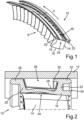
- Fig. 1 shows a perspective view of two guide vane clusters 10 according to the invention, which are arranged in a manner known per se with further guide vane clusters 10 in a ring-shaped manner as a stator group in a housing 12 (see Fig. 2 ) of a gas turbine (not shown), in particular of an aircraft engine.
- Each guide vane cluster 10 has a plurality of blades 14, which are connected to one another via a common, radially outer platform 16.
- the platform 16 forms a shroud for delimiting a flow channel S of the associated gas turbine.
- the guide vane clusters 10 are designed in the so-called “cantilevered" construction, so that the blade tips 18 of the blades 14 are exposed.
- Fig. 1 shows a perspective view of two guide vane clusters 10 according to the invention, which are arranged in a manner known per se with further guide vane clusters 10 in a ring-shaped manner as a stator group in a housing 12 (see Fig. 2 ) of a
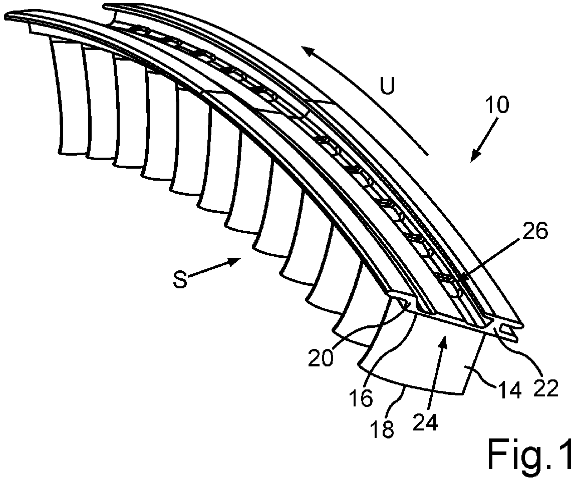
- Fig. 2 shows a schematic sectional view through the platform 16 of a guide vane cluster 10 arranged on the casing 12 of the gas turbine.
- the platform 16 has an upstream flange 20 extending radially from the platform 16 and a downstream flange 22 extending radially from the platform 16.
- the flanges 20, 22, together with a section 24 of the platform 16 lying between the flanges 20, 22, form a groove 26 extending in the circumferential direction U of the gas turbine or the casing.
- a clamp-shaped damping element 28 is arranged in the groove 26 for vibration damping.
- a surface of section 24 of platform 16 that defines groove 26 is curved, at least in some areas, radially toward a radially upper opening of groove 26.
- the surface of platform 16 that forms the "bottom" or a wall region of groove 26 is not flat or circular-cylindrical segment-shaped in the circumferential direction, but rather has a convex curvature in cross-section in the axial direction, which can also be referred to as a relative thickening, rib, or contact rib.
- Such an "uneven" shape of the “bottom” of groove 26 enables improved frictional contact and thus improved power transmission for damping element 28 arranged in groove 26, which can accordingly form more uniform and reliable contact with a guide vane or guide vane cluster 10 and thus realize improved vibration damping.
- Fig. 1 one can see the rib-shaped "thickening" or deformation of the platform 16, which is formed circumferentially in a fully assembled guide vane ring How to Fig. 2
- a surface of the section 24 of the platform 16 facing away from the groove 26 can also be curved radially in the direction of the opening of the groove 26, at least in some regions, whereby the section 24 of the platform 16 has an at least substantially uniform or constant wall thickness in cross-section.
- the platform 16 thus has an aerodynamically favorable wall contour for the working medium flowing past during operation of the gas turbine.
- the guide vane or the guide vane cluster 10 is additively manufactured so that the aforementioned geometric features can be realized simply and reliably.
- the presently U-shaped damping element 28 has at least three contact points or surfaces and rests upstream on the flange 20, in its central region on the rib-shaped section 24, and downstream on the flange 22. As can be seen in Fig.
- the downstream flange 22 has a downstream inclined wall against which a downstream leg of the damping element 28 rests, as well as an upstream projection 30 at its radially outer end region, which projects into the groove 26 or delimits the opening of the groove 26, thereby creating a type of pocket or fall-out prevention device and, if necessary, an additional contact point for the damping element 28.
- the downstream flange 22 has a downstream projection 32, which together with the platform 16 forms a further groove 34, which also runs circumferentially and is suitable for receiving fastening hooks or the like for securing the guide vane cluster 10 to the housing 12, a sealing element or other static components.
- the flange 22 thus has an approximately T-shaped cross-section. Independently of the flange 22, the flange 20 can in principle also have a T-shaped configuration.
- the upstream flange 20 in turn, has an upstream-inclined wall against which an upstream leg of the damping element 28 rests. Furthermore, the flange 20 comprises an upstream projection 36, which also serves to secure the guide vane cluster 10. The projections 30, 32, 36 also function as additional damping elements.
- Fig. 3 shows a schematic and partial perspective view of the guide vane cluster 10 arranged on the housing 12, wherein an alternative damping element 28 is arranged in the groove 26.
- the general structure of the guide vane cluster 10 corresponds to the previous embodiment.
- the damping element 28 is clamp-shaped or partially bent over itself.
- the damping element 28 has a contact point IIIb with itself and optionally a contact point IIIc with the housing 12. Vibration damping can therefore be achieved not only by friction with the guide vane cluster 10, but also by friction within itself and, if appropriate, by friction with the housing 12.
- Fig. 4 shows a schematic and partial perspective view of a platform 16 of a guide vane cluster 10, wherein a further alternative damping element 28 is arranged in the groove 26.
- the platform 16 is not deformed in the section 24 on its side facing the flow channel S, but has a flat contour.
- the damping element 28 has a recess 38 in the contact area with the section 24 of the platform 16 to adapt its damping properties. It can also be seen that an end area E of the damping element 28 runs obliquely with respect to the edge of the platform 16 and does not end flush with the platform 16.
- the damping elements 28 of adjacent guide vane clusters 10 can be arranged overlapping or across segments, which advantageously makes additional sealing plates or the like unnecessary.
- the damping element 28 can be designed as a straight element, which simplifies its production.
Landscapes
- Engineering & Computer Science (AREA)
- Mechanical Engineering (AREA)
- General Engineering & Computer Science (AREA)
- Turbine Rotor Nozzle Sealing (AREA)
Abstract
Die Erfindung betrifft eine Leitschaufel für eine Gasturbine, umfassend ein Schaufelblatt (14), eine an einem radialen Ende des Schaufelblatts (14) angeordnete Plattform (16), einen sich radial von der Plattform (16) erstreckenden stromaufwärtigen Flansch (20) und einen sich radial von der Plattform (16) erstreckenden stromabwärtigen Flansch (22), wobei die Flansche (20, 22) zusammen mit einem zwischen den Flanschen (20, 22) liegenden Abschnitt (24) der Plattform (16) eine sich in Umfangsrichtung (U) der Gasturbine erstreckende Nut (26) zur Anordnung eines Dämpfungselements (28) begrenzen. Eine die Nut (26) begrenzende Oberfläche des Abschnitts (24) der Plattform (16) ist zumindest bereichsweise radial in Richtung einer Öffnung der Nut (26) gewölbt. Die Erfindung betrifft weiterhin ein Leitschaufelcluster (10), ein Gehäuse (12) für eine Gasturbine sowie eine Gasturbine.
Description
- Die Erfindung betrifft eine Leitschaufel, ein Leitschaufelcluster sowie ein Gehäuse für eine Gasturbine, insbesondere für ein Flugtriebwerk. Die Erfindung betrifft weiterhin eine Gasturbine mit entsprechend ausgebildeten Leitschaufeln bzw. Leitschaufelclustern und/oder einem entsprechend ausgebildeten Gehäuse.
- Leitschaufeln bzw. Leitschaufelcluster für Gasturbinen sind bereits aus dem Stand der Technik bekannt und dienen als Statorbaugruppen im Strömungskanal eines Gehäuses der Gasturbine dazu, die Strömung des Arbeitsmediums in der Gasturbine zu steuern und eine gewünschte Anströmung stromabliegender Laufschaufeln eines Rotors sicherzustellen. Dies ermöglicht eine effiziente Energieumwandlung und Leistungsgewinnung. Leitschaufelcluster umfassen zwei oder mehr Leitschaufeln, die über wenigstens eine gemeinsame Plattform zur radialen Begrenzung des Strömungskanals miteinander verbunden sind. Jede Schaufel weist dabei ein Schaufelblatt mit einer Saugseite und einer Druckseite auf, die in einer stromaufwärtigen, im Betrieb vom Arbeitsfluid der Strömungsmaschine angeströmten Vorderkante und einer axial gegenüberliegenden, stromabwärts anzuordnenden Hinterkante miteinander verbunden sind. Mehrere Leitschaufeln bzw. Leitschaufelcluster werden in Form eines Leitschaufelrings oder Leitschaufelkranzes in einem Verdichter und/oder einer Turbine der Strömungsmaschine feststehend gegenüber einem Gehäuse der Strömungsmaschine angeordnet.
- Aus der
DE 39 17 937 A1 ist es bekannt, die Plattform von Leitschaufeln bzw. Leitschaufelclustern mit einem sich radial von der Plattform erstreckenden stromaufwärtigen Flansch und einem sich radial von der Plattform erstreckenden stromabwärtigen Flansch zu versehen, wobei die Flansche zusammen mit einem zwischen den Flanschen liegenden Abschnitt der Plattform eine sich in Umfangsrichtung der Gasturbine erstreckende Nut zur Anordnung eines Dämpfungselements begrenzen. Über die Flansche kann eine Anbindung der Plattform an das Gehäuse bzw. eine Dichtung erfolgen. Das in der Nut angeordnete Dämpfungselement sorgt aufgrund seines Reibkontakts für eine Schwindungsdämpfung der Leitschaufeln. Die Schwingungen entstehen im Wesentlichen durch die Wirbelschleppen und Druckschwankungen des an den Leitschaufeln entlang strömenden Arbeitsmediums, welche zu Biege- und Torsionsbeanspruchungen der Leitschaufeln führen. Eine Dämpfung der Leitschaufeln ist daher wichtig, um die Schwingungsamplituden zu reduzieren, da es ansonsten zu Schwingermüdungen und erhöhte Bruchwahrscheinlichkeit kommen kann. - Wie sich herausgestellt hat, sind bestehende Schwingungsdämpfungslösungen aber nicht immer ausreichend. Insbesondere im Dauerfestigkeitsbereich (engl. high cycle fatigue, HCF) kann es durch die dynamische Beanspruchung nach mehreren Lastwechseln zu Schwinganrissen kommen, die makroskopisch zunächst ohne eine unmittelbar erkennbare plastische Verformung erfolgen können. Dies betrifft nicht nur aber insbesondere sogenannte "cantilevered" Leitschaufeln bzw. Leitschaufelcluster mit freiliegenden Schaufelspitzen.
- Aufgabe der vorliegenden Erfindung ist es, eine Leitschaufel für eine Gasturbine zu schaffen, welche eine verbesserte Schwingungsdämpfung ermöglicht. Weitere Aufgaben der Erfindung bestehen darin, ein entsprechendes Leitschaufelcluster mit der Möglichkeit einer verbesserten Schwingungsdämpfung, ein Gehäuse für eine Gasturbine mit entsprechend verbesserten Leitschaufeln bzw. Leitschaufelclustern sowie eine entsprechend verbesserte Gasturbine zu schaffen.
- Die Aufgaben werden erfindungsgemäß durch eine Leitschaufel gemäß Anspruch 1, durch ein Leitschaufelcluster gemäß Anspruch 5, durch ein Gehäuse gemäß Anspruch 6 sowie durch eine Gasturbine gemäß Anspruch 10 gelöst. Vorteilhafte Ausgestaltungen mit zweckmäßigen Weiterbildungen der Erfindung sind in den jeweiligen Unteransprüchen angegeben, wobei vorteilhafte Ausgestaltungen jedes Erfindungsaspekts als vorteilhafte Ausgestaltungen der jeweils anderen Erfindungsaspekte und umgekehrt anzusehen sind.
- Ein erster Erfindungsaspekt betrifft eine Leitschaufel für eine Gasturbine, umfassend ein Schaufelblatt, eine an einem radialen Ende des Schaufelblatts angeordnete Plattform, einen sich radial von der Plattform erstreckenden stromaufwärtigen Flansch und einen sich radial von der Plattform erstreckenden stromabwärtigen Flansch, wobei die Flansche zusammen mit einem zwischen den Flanschen liegenden Abschnitt der Plattform eine sich in Umfangsrichtung der Gasturbine erstreckende Nut zur Anordnung eines Dämpfungselements begrenzen. Eine verbesserte Schwingungsdämpfung ist erfindungsgemäß dadurch ermöglicht, dass eine die Nut begrenzende Oberfläche des Abschnitts der Plattform zumindest bereichsweise radial in Richtung einer Öffnung der Nut gewölbt ist. Mit anderen Worten ist die den "Boden" bzw. einen Wandbereich der Nut bildende Oberfläche der Plattform nicht wie bisher plan bzw. in Umfangsrichtung kreiszylindersegmentförmig ausgebildet, sondern weist im Querschnitt in axialer Richtung eine konvexe Wölbung auf, die auch als relative Aufdickung oder Rippe bezeichnet werden kann. Eine solche "unebene" Form des "Bodens" der Nut ermöglicht einen verbesserten Reibkontakt und damit eine verbesserte Kraftübertragung für ein in der Nut angeordnetes Dämpfungselement, das dementsprechend einen gleichmäßigeren und betriebssichereren Kontakt zur Leitschaufel ausbilden und damit eine verbesserte Schwingungsdämpfung realisieren kann. Die Geometrie des Dämpfungselements kann dabei nahezu beliebig sein, solange es einen Kontakt zumindest mit der gewölbten Oberfläche der Nut ausbilden kann. Die Richtungsangaben "radial" bzw. "Radial-", "axial-" bzw. "Axial-" und "Umfangs-" beziehen sich im Rahmen der vorliegenden Erfindung immer auf die Maschinenachse einer Gasturbine, wenn die erfindungsgemäße Leitschaufel bzw. das erfindungsgemäße Leitschaufelcluster in dieser bestimmungsgemäß montiert ist, sofern sich aus dem Kontext nicht explizit oder implizit etwas anderes ergibt. Neben der Schwingungsdämpfung infolge Energiedissipation bei Reibung besitzt das Dämpfungselement, das grundsätzlich auch als Reibkontakt bezeichnet werden kann, eine weitere Fähigkeit, um Schwingungsbeanspruchung zu reduzieren. Diese Reduktion erfolgt durch Absorption oder Umverteilung der Energie aus einer zu dämpfenden Schwingungsform in eine andere, höhere und/oder niedrigere Schwingungsform. Das Dämpfungselement kann also generell entweder für Energiedissipation oder für Absorption (Energietransfer/-umwandlung) ausgelegt oder für eine Kombination aus beiden Dämpfungsformen ausgelegt sein und verwendet werden.
- In einer vorteilhaften Ausgestaltung der Erfindung ist vorgesehen, dass eine von der Nut abgewandte Oberfläche des Abschnitts der Plattform zumindest bereichsweise radial in Richtung der Öffnung der Nut gewölbt ist und/oder dass der Abschnitt der Plattform im Querschnitt eine zumindest im Wesentlichen einheitliche Wandstärke besitzt. Mit anderen Worten ist es erfindungsgemäß vorgesehen, dass auch die dem Arbeitsmedium der Gasturbine zugewandte Oberfläche der Plattform in axialer Richtung von einer stromaufwärtigen Seite zu einer stromabwärtigen Seite betrachtet uneben und vorzugsweise konkav, das heißt ebenfalls in radialer Richtung zur Öffnung der Nut hin verformt ausgebildet ist. Neben aerodynamischen Vorteilen durch eine solche gewölbte Oberfläche der Plattform im Bereich des vorbeiströmenden Arbeitsfluids kann dabei trotzdem eine zumindest im Wesentlichen einheitliche Wandstärke der Plattform beibehalten werden, so dass durch die beschriebene relative Verformung bzw. Konturierung der Plattform keine zusätzlichen Schwingungs- oder Festigkeitsprobleme entstehen.
- Weitere Vorteile ergeben sich dadurch, dass das Schaufelblatt gegenüber der Plattform eine freiliegende Schaufelspitze aufweist. Mit anderen Worten ist die Leitschaufel in der sogenannten "cantilevered"-Bauweise ausgeführt, also mit einem freien Schaufelende an der Nabe und einem entsprechenden Radialspalt. Statoren mit Deckband liefern aufgrund der Verbindung benachbarter Schaufelblätter in der Regel ein mechanisch stabileres System mit vergleichsweise geringerer Schwingungsneigung der Leitschaufeln auf Kosten einer deutlich komplizierteren Geometrie und damit verbundenen höheren Fertigungskosten. Im Gegensatz dazu sind "cantilevered" Leitschaufeln ohne zusätzliche Plattform oder Deckband vergleichsweise schwingungsanfälliger, jedoch deutlich preiswerter in der Fertigung. Aufgrund der erfindungsgemäß verbesserten Dämpfungseigenschaften können diese potenziellen Nachteile der "cantilevered"-Bauweise überwunden werden.
- In einer weiteren vorteilhaften Ausgestaltung der Erfindung ist vorgesehen, dass der stromaufwärtige Flansch eine stromabwärtige Auskragung in die Nut aufweist und/oder dass der stromabwärtige Flansch eine stromaufwärtige Auskragung in die Nut umfasst. Hierdurch kann eine einseitige oder zweiseitige hakenartige Sperre realisiert werden, die ein Herausfallen eines in der Nut angeordneten Dämpfungselements besonders zuverlässig verhindert und darüber hinaus zusätzliche Kontaktstellen für das Dämpfungselement bilden kann. Alternativ oder zusätzlich ist es vorgesehen, dass der stromaufwärtige Flansch eine stromaufwärtige Auskragung aufweist, welche zusammen mit der Plattform eine weitere, sich in Umfangsrichtung der Gasturbine erstreckende Nut bildet und/oder dass der stromabwärtige Flansch eine stromabwärtige Auskragung aufweist, welche zusammen mit der Plattform eine weitere sich in Umfangsrichtung der Gasturbine erstreckende Nut bildet. Auf diese Weise kann ein die Plattform über in die Nut bzw. Nuten eingreifende Haltehaken besonders einfach und zuverlässig am Gehäuse, einem Dichtungselement oder dergleichen befestigt werden. Ein weiterer Vorteil der genannten Auskragungen, einzeln und in beliebiger Kombination, besteht darin, dass sie zusätzlich zu einem in der Nut der Plattform angeordneten Dämpfungselements ein inhärentes, weiteres Dämpfungselement für zusätzliche Schwingungsdämpfung bilden.
- Ein zweiter Aspekt der Erfindung betrifft ein Leitschaufelcluster für eine Gasturbine, bei welchem mindestens zwei Leitschaufeln gemäß dem ersten Erfindungsaspekt über wenigstens eine gemeinsame Plattform zur radialen Begrenzung eines Strömungskanals der Gasturbine miteinander verbunden sind. Hierdurch können die im Zusammenhang mit dem ersten Erfindungsaspekt beschriebenen Vorteile und insbesondere der verbesserten Reibkontakt und die damit eine verbesserte Schwingungsdämpfung für ein in der Nut der Plattform des Leitschaufelclusters angeordnetes Dämpfungselement auch bei einem Leitschaufelcluster mit zwei, drei, vier oder mehr Schaufelblättern realisiert werden.
- Ein dritter Aspekt der Erfindung betrifft ein Gehäuse für eine Gasturbine, mit einem Strömungskanal, in welchem mehrere Leitschaufeln gemäß dem ersten Erfindungsaspekt und/oder mehrere Leitschaufelcluster gemäß dem zweiten Erfindungsaspekt kranzförmig angeordnet sind, wobei die sich in Umfangsrichtung der Gasturbine erstreckenden Nuten der Leitschaufeln und/oder Leitschaufelcluster miteinander fluchten und wobei wenigstens ein Dämpfungselement in wenigstens einer der Nuten angeordnet ist. Hierdurch kann aus den vorstehend beschriebenen Gründen eine verbesserte Schwingungsdämpfung realisiert werden. Das Dämpfungselement kann generell einteilig oder mehrteilig ausgebildet sein und erstreckt sich vorzugsweise entlang des gesamten Umfangs des aus den Leitschaufeln bzw. Leitschaufelclustern gebildeten Leitschaufelkranzes für eine optimale Schwingungsdämpfung.
- In einer vorteilhaften Ausgestaltung der Erfindung ist vorgesehen, dass das wenigstens ein Dämpfungselement eine Aussparung im Bereich des radial in Richtung einer Öffnung der Nut gewölbt Abschnitts der zugeordneten Plattform aufweist. Hierdurch kann neben einer Gewichtsreduktion insbesondere ein gezieltes "Verstimmen" des Dämpfungselements erzielt werden, wodurch eine einfache Anpassbarkeit an die Eigenfrequenzen und die Schwingungsantwort der jeweiligen Leitschaufeln erzielbar ist. Alternativ oder zusätzlich ist vorgesehen, dass das Dämpfungselement im Querschnitt u-förmig oder o-förmig oder klammerförmig ausgebildet ist. Alternativ oder zusätzlich ist vorgesehen, dass das Dämpfungselement in Umfangsrichtung linear ausgebildet ist. Dies ist insbesondere für vergleichsweise kurze Dämpfungselemente, bei denen eine Krümmung der Leitschaufel bzw. des Leitschaufelclusters vernachlässigt werden kann, sinnvoll, da das Dämpfungselement hierdurch besonders kostengünstig hergestellt werden kann ohne komplexe Krümmungen realisieren zu müssen.
- Eine besonders zuverlässige Schwingungsdämpfung ergibt sich in weiterer Ausgestaltung dadurch, dass das Dämpfungselement im Querschnitt mindestens drei Anlagepunkte in der Nut aufweist und/oder dass das Dämpfungselement wenigstens einen und vorzugsweise mindestens zwei Anlagepunkte mit dem Gehäuse aufweist. Anstelle eines Anlagepunkts kann generell auch eine flächige Anlage vorgesehen sein.
- In einer weiteren vorteilhaften Ausgestaltung der Erfindung ist vorgesehen, dass das Dämpfungselement überbrückend zwischen mindestens zwei aneinander angrenzenden Leitschaufeln und/oder Leitschaufelclustern angeordnet ist. Auf diese Weise kann das Dämpfungselement vorteilhaft auch als Dichtelement wirken, wodurch zusätzliche Standarddichtbleche und dergleichen zwischen den benachbarten Leitschaufeln bzw. Leitschaufelclustern entfallen können.
- Ein vierter Aspekt der Erfindung betrifft eine Gasturbine, insbesondere Flugtriebwerk, mit wenigstens einer Leitschaufel gemäß dem ersten Erfindungsaspekt und/oder wenigstens einem Leitschaufelcluster gemäß dem zweiten Erfindungsaspekt und/oder wenigstens einem Gehäuse gemäß dem dritten Erfindungsaspekt. Die sich hieraus ergebenden Merkmale und deren Vorteile sind den vorhergehenden Beschreibungen der ersten drei Erfindungsaspekte zu entnehmen.
- Weitere Merkmale der Erfindung ergeben sich aus den Ansprüchen und den Ausführungsbeispielen. Die in der vorangegangenen Beschreibung erwähnten Merkmale und Kombinationen von Merkmalen sowie die in den folgenden Beispielen genannten Merkmalskombinationen können nicht nur in den jeweils angegebenen Kombinationen verwendet werden, sondern auch in anderen Kombinationen oder in Alleinstellung, ohne den Rahmen der Erfindung zu verlassen. Es sind daher auch Ausführungen der Erfindung als mitumfasst und offenbart anzusehen, die in den Beispielen nicht ausdrücklich gezeigt und erläutert werden. Es sind auch Ausführungen und Kombinationen von Merkmalen als offenbart anzusehen, die nicht alle Merkmale eines ursprünglich formulierten unabhängigen Anspruchs aufweisen. Dabei zeigt:
- Fig. 1
- eine Perspektivansicht von zwei erfindungsgemäßen Leitschaufelclustern;
- Fig. 2
- eine schematische Schnittansicht durch eine Plattform eines an einem Gehäuse einer Gasturbine angeordneten Leitschaufelclusters;
- Fig. 3
- eine schematische und ausschnittsweise Perspektivansicht des am Gehäuse angeordneten Leitschaufelclusters, wobei ein alternatives Dämpfungselement in einer Nut angeordnet ist; und
- Fig. 4
- eine schematische und ausschnittsweise Perspektivansicht auf eine Plattform eines Leitschaufelclusters, wobei ein weiteres alternatives Dämpfungselement in der Nut angeordnet ist.
-
Fig. 1 zeigt eine Perspektivansicht von zwei erfindungsgemäßen Leitschaufelclustern 10, die in an sich bekannter Weise mit weiteren Leitschaufelclustern 10 kranzförmig als Statorgruppe in einem Gehäuse 12 (s.Fig. 2 ) einer Gasturbine (nicht gezeigt), insbesondere eines Flugtriebwerks, angeordnet werden. Jedes Leitschaufelcluster 10 weist mehrere Schaufelblätter 14 auf, die über eine gemeinsame, radial äußere Plattform 16 miteinander verbunden sind. Die Plattform 16 bildet ein Deckband zur Begrenzung eines Strömungskanals S der zugeordneten Gasturbine. Im gezeigten Ausführungsbeispiel sind die Leitschaufelcluster 10 in der sogenannten "cantilevered"-Bauweise ausgeführt, so dass die Schaufelspitzen 18 der Schaufelblätter 14 freiliegen.Fig. 1 wird im Folgenden in Zusammenschau mitFig. 2 erläutert, welche eine schematische Schnittansicht durch die Plattform 16 eines am Gehäuse 12 der Gasturbine angeordneten Leitschaufelclusters 10 zeigt. Man erkennt, dass die Plattform 16 einen sich radial von der Plattform 16 erstreckenden stromaufwärtigen Flansch 20 und einen sich radial von der Plattform 16 erstreckenden stromabwärtigen Flansch 22 aufweist. Die Flansche 20, 22 bilden zusammen mit einem zwischen den Flanschen 20, 22 liegenden Abschnitt 24 der Plattform 16 eine sich in Umfangsrichtung U der Gasturbine bzw. des Gehäuses erstreckende Nut 26. Wie inFig. 2 gezeigt, wird in der Nut 26 ein klammerförmiges Dämpfungselement 28 zur Schwingungsdämpfung angeordnet. Wie man insbesondere inFig. 2 erkennt, ist eine die Nut 26 begrenzende Oberfläche des Abschnitts 24 der Plattform 16 zumindest bereichsweise radial in Richtung einer radial oberen Öffnung der Nut 26 gewölbt. Mit anderen Worten ist die den "Boden" bzw. einen Wandbereich der Nut 26 bildende Oberfläche der Plattform 16 nicht plan bzw. in Umfangsrichtung kreiszylindersegmentförmig ausgebildet, sondern weist im Querschnitt in axialer Richtung eine konvexe Wölbung auf, die auch als relative Aufdickung, Rippe oder Kontaktrippe bezeichnet werden kann. Eine solche "unebene" Form des "Bodens" der Nut 26 ermöglicht einen verbesserten Reibkontakt und damit eine verbesserte Kraftübertragung für das in der Nut 26 angeordnetes Dämpfungselement 28, das dementsprechend einen gleichmäßigeren und betriebssichereren Kontakt zu einer Leitschaufel bzw. dem Leitschaufelcluster 10 ausbilden und damit eine verbesserte Schwingungsdämpfung realisieren kann. InFig. 1 erkennt man die rippenförmige "Aufdickung" oder Verformung der Plattform 16, die bei einem voll montierten Leitschaufelkranz umfangsseitig umlaufend ausgebildet ist. Wie man inFig. 2 erkennt, kann in manchen Ausgestaltungen auch eine von der Nut 26 abgewandte Oberfläche des Abschnitts 24 der Plattform 16 zumindest bereichsweise radial in Richtung der Öffnung der Nut 26 gewölbt sein, wodurch der Abschnitt 24 der Plattform 16 im Querschnitt eine zumindest im Wesentlichen einheitliche oder konstante Wandstärke besitzt. Darüber hinaus besitzt die Plattform 16 damit eine aerodynamisch günstige Wandkontur für das im Betrieb der Gasturbine vorbeiströmende Arbeitsmedium. Vorzugsweise ist die Leitschaufel bzw. das Leitschaufelcluster 10 additiv gefertigt, damit die genannten geometrischen Features einfach und zuverlässig realisiert werden können. Das vorliegend u-förmige Dämpfungselement 28 besitzt mindestens drei Anlagepunkte bzw. -flächen und liegt stromauf am Flansch 20 an, im seinem Mittelbereich auf dem rippenförmigen Abschnitt 24 und stromab am Flansch 22. Wie man inFig. 2 weiterhin erkennt, besitzt der stromabwärtige Flansch 22 eine stromabwärtig geneigte Wand, an welcher ein stromabwärtiger Schenkel des Dämpfungselements 28 anliegt, sowie an seinem radial äußeren Endbereich eine stromaufwärtige Auskragung 30, die in die Nut 26 ragt bzw. die Öffnung der Nut 26 begrenzt, wodurch eine Art Tasche oder Herausfallsicherung sowie gegebenenfalls ein zusätzlicher Anlagepunkt für das Dämpfungselement 28 realisiert ist. Weiterhin besitzt der stromabwärtige Flansch 22 eine stromabwärtige Auskragung 32, die zusammen mit der Plattform 16 eine weitere Nut 34 bildet, die ebenfalls umfangsseitig umläuft und zur Aufnahme von Befestigungshaken oder dergleichen zum Festlegen des Leitschaufelclusters 10 am Gehäuse 12, einem Dichtelement oder anderen statischen Bauelementen geeignet ist. Der Flansch 22 weist damit im Querschnitt eine näherungsweise T-förmige Gestalt auf. Unabhängig vom Flansch 22 kann grundsätzlich auch der Flansch 20 eine T-förmige Gestalt aufweisen. - Der stromaufwärtige Flansch 20 weist seinerseits eine stromaufwärtig geneigte Wand auf, an welcher ein stromaufwärtiger Schenkel des Dämpfungselements 28 anliegt. Weiterhin umfasst der Flansch 20 eine stromaufwärtige Auskragung 36, die ebenfalls zur Befestigung des Leitschaufelclusters 10 dient. Die Auskragungen 30, 32, 36 fungieren zudem ihrerseits als zusätzliche Dämpfungselemente.
-
Fig. 3 zeigt eine schematische und ausschnittsweise Perspektivansicht des am Gehäuse 12 angeordneten Leitschaufelclusters 10, wobei ein alternatives Dämpfungselement 28 in der Nut 26 angeordnet ist. Der generelle Aufbau des Leitschaufelclusters 10 entspricht dem vorhergehenden Ausführungsbeispiel. Im Unterschied zum u-förmigen Dämpfungselement 28 ausFig. 2 ist das Dämpfungselement 28 vorliegend klammerförmig bzw. bereichsweise über sich selbst gebogen. - Hierdurch weist das Dämpfungselement 28 zusätzlich zu den vorgenannten drei Anlagepunkten oder -flächen IIIa in der Nut eine Kontaktstelle IIIb mit sich selbst sowie optional eine Kontaktstelle IIIc mit dem Gehäuse 12 auf. Die Schwingungsdämpfung kann daher nicht nur durch Reibung mit dem Leitschaufelcluster 10, sondern auch durch Reibung in sich selbst sowie gegebenenfalls durch Reibung mit dem Gehäuse 12 realisiert werden.
-
Fig. 4 zeigt eine schematische und ausschnittsweise Perspektivansicht auf eine Plattform 16 eines Leitschaufelclusters 10, wobei ein weiteres alternatives Dämpfungselement 28 in der Nut 26 angeordnet ist. Im Unterschied zu den vorhergehenden Ausführungsbeispielen ist die Plattform 16 im Abschnitt 24 auf ihrer dem Strömungskanal S zugewandten Seite nicht verformt, sondern besitzt eine ebene Kontur. Weiterhin weist das Dämpfungselement 28 zur Anpassung seiner Dämpfungseigenschaften eine Aussparung 38 im Kontaktbereich mit dem Abschnitt 24 der Plattform 16 auf. Weiterhin erkennt man, dass ein Endbereich E des Dämpfungselements 28 schräg bezüglich des Rands der Plattform 16 verläuft und nicht bündig mit der Plattform 16 abschließt. Hierdurch können die Dämpfungselemente 28 benachbarter Leitschaufelcluster 10 überlappend bzw. segmentübergreifend angeordnet werden, wodurch vorteilhaft auf zusätzliche Dichtbleche oder dergleichen verzichtet werden kann. Bei kurzen Leitschaufelclustern 10 bzw. Einzelschaufeln kann das Dämpfungselement 28 als gerades Element ausgeführt werden, was seine Fertigung vereinfacht. -
- 10
- Leitschaufelcluster
- 12
- Gehäuse
- 14
- Schaufelblatt
- 16
- Plattform
- 18
- Schaufelspitze
- 20
- Flansch
- 22
- Flansch
- 24
- Abschnitt
- 26
- Nut
- 28
- Dämpfungselement
- 30
- Auskragung
- 32
- Auskragung
- 34
- Nut
- 36
- Auskragung
- 38
- Aussparung
- S
- Strömungskanal
- E
- Endbereich
- U
- Umfangsrichtung
- IIIa-c
- Anlagepunkte
Claims (10)
- Leitschaufel für eine Gasturbine, umfassend ein Schaufelblatt (14), eine an einem radialen Ende des Schaufelblatts (14) angeordnete Plattform (16), einen sich radial von der Plattform (16) erstreckenden stromaufwärtigen Flansch (20) und einen sich radial von der Plattform (16) erstreckenden stromabwärtigen Flansch (22), wobei die Flansche (20, 22) zusammen mit einem zwischen den Flanschen (20, 22) liegenden Abschnitt (24) der Plattform (16) eine sich in Umfangsrichtung (U) der Gasturbine erstreckende Nut (26) zur Anordnung eines Dämpfungselements (28) begrenzen, dadurch gekennzeichnet, dass eine die Nut (26) begrenzende Oberfläche des Abschnitts (24) der Plattform (16) zumindest bereichsweise radial in Richtung einer Öffnung der Nut (26) gewölbt ist.
- Leitschaufel nach Anspruch 1, dadurch gekennzeichnet, dass eine von der Nut (26) abgewandte Oberfläche des Abschnitts (24) der Plattform (16) zumindest bereichsweise radial in Richtung der Öffnung der Nut (26) gewölbt ist und/oder dass der Abschnitt (24) der Plattform (16) im Querschnitt eine zumindest im Wesentlichen einheitliche Wandstärke besitzt.
- Leitschaufel nach Anspruch 1 oder 2, dadurch gekennzeichnet, dass das Schaufelblatt (14) gegenüber der Plattform (16) eine freiliegende Schaufelspitze (18) aufweist.
- Leitschaufel nach einem der Ansprüche 1 bis 3, dadurch gekennzeichnet, dass der stromaufwärtige Flansch (20) eine stromabwärtige Auskragung (30, 32, 36) in die Nut (26) aufweist und/oder dass der stromabwärtige Flansch (22) eine stromaufwärtige Auskragung (30) in die Nut (26) umfasst und/oder dass der stromaufwärtige Flansch (20) eine stromaufwärtige Auskragung (36) aufweist, welche zusammen mit der Plattform (16) eine weitere sich in Umfangsrichtung (U) der Gasturbine erstreckende Nut (26, 34) bildet und/oder dass der stromabwärtige Flansch (22) eine stromabwärtige Auskragung (32) aufweist, welche zusammen mit der Plattform (16) eine weitere, sich in Umfangsrichtung (U) der Gasturbine erstreckende Nut (34) bildet.
- Leitschaufelcluster (10) für eine Gasturbine, bei welchem mindestens zwei Leitschaufeln nach einem der Ansprüche 1 bis 4 über wenigstens eine gemeinsame Plattform (16) zur radialen Begrenzung eines Strömungskanals (S) der Gasturbine miteinander verbunden sind.
- Gehäuse (12) für eine Gasturbine, mit einem Strömungskanal, in welchem mehrere Leitschaufeln gemäß einem der Ansprüche 1 bis 4 und/oder mehrere Leitschaufelcluster (10) gemäß Anspruch 5 kranzförmig angeordnet sind, wobei die sich in Umfangsrichtung (U) der Gasturbine erstreckenden Nuten (26, 34) der Leitschaufeln und/oder Leitschaufelcluster (10) miteinander fluchten und wobei wenigstens ein Dämpfungselement (28) in wenigstens einer der Nuten (26) angeordnet ist.
- Gehäuse (12) nach Anspruch 6, dadurch gekennzeichnet, dass das wenigstens ein Dämpfungselement (28) eine Aussparung (38) im Bereich des radial in Richtung einer Öffnung der Nut (26) gewölbt Abschnitts (24) der zugeordneten Plattform (16) aufweist und/oder dass das Dämpfungselement (28) im Querschnitt u-förmig oder o-förmig oder klammerförmig ausgebildet ist und/oder dass das Dämpfungselement (28) in Umfangsrichtung (U) linear ausgebildet ist.
- Gehäuse (12) nach Anspruch 6 oder 7, dadurch gekennzeichnet, dass das Dämpfungselement (28) im Querschnitt mindestens drei Anlagepunkte (IIIa-c) in der Nut (26) aufweist und/oder dass das Dämpfungselement (28) wenigstens einen und vorzugsweise mindestens zwei Anlagepunkte (IIIc) mit dem Gehäuse (12) aufweist.
- Gehäuse (12) nach einem der Ansprüche 6 bis 8, dadurch gekennzeichnet, dass das Dämpfungselement (28) überbrückend zwischen mindestens zwei aneinander angrenzenden Leitschaufeln und/oder Leitschaufelclustern (10) angeordnet ist.
- Gasturbine, insbesondere Flugtriebwerk, mit wenigstens einer Leitschaufel nach einem der Ansprüche 1 bis 4 und/oder wenigstens einem Leitschaufelcluster (10) gemäß Anspruch 5 und/oder wenigstens einem Gehäuse (12) nach einem der Ansprüche 6 bis 9.
Applications Claiming Priority (1)
| Application Number | Priority Date | Filing Date | Title |
|---|---|---|---|
| DE102023128456.8A DE102023128456A1 (de) | 2023-10-17 | 2023-10-17 | Leitschaufel, Leitschaufelcluster und Gehäuse für eine Gasturbine sowie Gasturbine |
Publications (1)
| Publication Number | Publication Date |
|---|---|
| EP4542007A1 true EP4542007A1 (de) | 2025-04-23 |
Family
ID=93150212
Family Applications (1)
| Application Number | Title | Priority Date | Filing Date |
|---|---|---|---|
| EP24207033.2A Pending EP4542007A1 (de) | 2023-10-17 | 2024-10-16 | Leitschaufel für eine gasturbine, leitschaufelcluster für eine gasturbine, gehäuse für eine gasturbine, und gasturbine |
Country Status (3)
| Country | Link |
|---|---|
| US (1) | US20250122807A1 (de) |
| EP (1) | EP4542007A1 (de) |
| DE (1) | DE102023128456A1 (de) |
Families Citing this family (1)
| Publication number | Priority date | Publication date | Assignee | Title |
|---|---|---|---|---|
| DE102024128303A1 (de) * | 2024-09-30 | 2026-04-02 | Rolls-Royce Deutschland Ltd & Co Kg | Frontstruktur für eine Verdichtervorrichtung eines Gasturbinentriebwerks, ein Verfahren zur Herstellung einer Frontstruktur und ein Gasturbinentriebwerk |
Citations (8)
| Publication number | Priority date | Publication date | Assignee | Title |
|---|---|---|---|---|
| DE3917937A1 (de) | 1988-06-02 | 1989-12-07 | United Technologies Corp | Statorbaugruppe fuer eine axialstroemungsmaschine |
| EP0522833A1 (de) * | 1991-07-09 | 1993-01-13 | General Electric Company | Hitzeschild für Verdichterstator |
| US5494404A (en) * | 1993-12-22 | 1996-02-27 | Alliedsignal Inc. | Insertable stator vane assembly |
| US20080019836A1 (en) * | 2004-02-11 | 2008-01-24 | Mtu Aero Engines Gmbh | Damping Arrangement for Guide Vanes |
| EP2613021A2 (de) * | 2012-01-05 | 2013-07-10 | United Technologies Corporation | Statorschaufel-Federdämpfer |
| US20160312800A1 (en) * | 2015-04-27 | 2016-10-27 | United Technologies Corporation | Stator Damper |
| FR3039201A1 (fr) * | 2015-07-22 | 2017-01-27 | Snecma | Partie de turbomachine a tole de protection thermique pourvue d'epingles |
| US20190055850A1 (en) * | 2017-08-17 | 2019-02-21 | United Technologies Corporation | Tuned airfoil assembly |
Family Cites Families (4)
| Publication number | Priority date | Publication date | Assignee | Title |
|---|---|---|---|---|
| US4431373A (en) * | 1980-05-16 | 1984-02-14 | United Technologies Corporation | Flow directing assembly for a gas turbine engine |
| US4784569A (en) * | 1986-01-10 | 1988-11-15 | General Electric Company | Shroud means for turbine rotor blade tip clearance control |
| EP2634373A1 (de) * | 2012-02-28 | 2013-09-04 | Siemens Aktiengesellschaft | Anordnung für eine Turbomaschine |
| US11047250B2 (en) * | 2019-04-05 | 2021-06-29 | Raytheon Technologies Corporation | CMC BOAS transverse hook arrangement |
-
2023
- 2023-10-17 DE DE102023128456.8A patent/DE102023128456A1/de active Pending
-
2024
- 2024-10-14 US US18/915,017 patent/US20250122807A1/en active Pending
- 2024-10-16 EP EP24207033.2A patent/EP4542007A1/de active Pending
Patent Citations (8)
| Publication number | Priority date | Publication date | Assignee | Title |
|---|---|---|---|---|
| DE3917937A1 (de) | 1988-06-02 | 1989-12-07 | United Technologies Corp | Statorbaugruppe fuer eine axialstroemungsmaschine |
| EP0522833A1 (de) * | 1991-07-09 | 1993-01-13 | General Electric Company | Hitzeschild für Verdichterstator |
| US5494404A (en) * | 1993-12-22 | 1996-02-27 | Alliedsignal Inc. | Insertable stator vane assembly |
| US20080019836A1 (en) * | 2004-02-11 | 2008-01-24 | Mtu Aero Engines Gmbh | Damping Arrangement for Guide Vanes |
| EP2613021A2 (de) * | 2012-01-05 | 2013-07-10 | United Technologies Corporation | Statorschaufel-Federdämpfer |
| US20160312800A1 (en) * | 2015-04-27 | 2016-10-27 | United Technologies Corporation | Stator Damper |
| FR3039201A1 (fr) * | 2015-07-22 | 2017-01-27 | Snecma | Partie de turbomachine a tole de protection thermique pourvue d'epingles |
| US20190055850A1 (en) * | 2017-08-17 | 2019-02-21 | United Technologies Corporation | Tuned airfoil assembly |
Also Published As
| Publication number | Publication date |
|---|---|
| DE102023128456A1 (de) | 2025-04-17 |
| US20250122807A1 (en) | 2025-04-17 |
Similar Documents
| Publication | Publication Date | Title |
|---|---|---|
| WO2007113149A1 (de) | Leitschaufel für eine strömungsmaschine, insbesondere für eine dampfturbine | |
| EP3199758B1 (de) | Rotor in blisk- oder bling-bauweise eines flugtriebwerks | |
| EP2455585B1 (de) | Anordnung für eine Axialturbomaschine sowie Axialturbomaschine | |
| EP2927503B1 (de) | Gasturbinenverdichter, Flugtriebwerk und Auslegungsverfahren | |
| EP3176370B1 (de) | Leitschaufelcluster für eine strömungsmaschine | |
| EP2299124A1 (de) | Verdichterlaufschaufel für einen Axialverdichter | |
| DE102017115042A1 (de) | Deckbandkonfigurationen für Turbinenlaufschaufeln | |
| DE102011055150A1 (de) | Turbinenschaufelanordnung | |
| WO2010007137A1 (de) | Axialturbomaschine mit geringen spaltverlusten | |
| EP2558685B1 (de) | Leitschaufel | |
| DE102016125091A1 (de) | Turbinenlaufschaufeln mit Spitzendeckband | |
| EP3988797A1 (de) | Axialventilator mit geräuschreduzierenden lüfterradschaufeln, die bohrungen aufweisen | |
| EP2746533A1 (de) | Schaufelgitter und Strömungsmaschine | |
| DE102019135798A1 (de) | Hybrid-laufschaufeln für turbinentriebwerke | |
| EP3034788A2 (de) | Kompressorschaufel einer gasturbine | |
| EP4542007A1 (de) | Leitschaufel für eine gasturbine, leitschaufelcluster für eine gasturbine, gehäuse für eine gasturbine, und gasturbine | |
| DE102019135335A1 (de) | Hybrid-laufschaufeln für turbinentriebwerke | |
| EP2394028B1 (de) | Abdichtvorrichtung an dem Schaufelschaft einer Rotorstufe einer axialen Strömungsmaschine und ihre Verwendung | |
| EP3056677B1 (de) | Schaufel und Strömungsmaschine | |
| WO2005116404A1 (de) | Schaufelblatt mit übergangszone | |
| EP2526263B1 (de) | Gehäusesystem für eine axialströmungsmaschine | |
| EP3309359B1 (de) | Laufschaufelbaugruppe für ein triebwerk | |
| EP3309360B1 (de) | Laufschaufelbaugruppe für ein triebwerk | |
| WO2003100220A1 (de) | Axialsicherung für laufschaufeln | |
| DE10352789B4 (de) | Gasturbine |
Legal Events
| Date | Code | Title | Description |
|---|---|---|---|
| PUAI | Public reference made under article 153(3) epc to a published international application that has entered the european phase |
Free format text: ORIGINAL CODE: 0009012 |
|
| STAA | Information on the status of an ep patent application or granted ep patent |
Free format text: STATUS: THE APPLICATION HAS BEEN PUBLISHED |
|
| AK | Designated contracting states |
Kind code of ref document: A1 Designated state(s): AL AT BE BG CH CY CZ DE DK EE ES FI FR GB GR HR HU IE IS IT LI LT LU LV MC ME MK MT NL NO PL PT RO RS SE SI SK SM TR |
|
| STAA | Information on the status of an ep patent application or granted ep patent |
Free format text: STATUS: REQUEST FOR EXAMINATION WAS MADE |
|
| 17P | Request for examination filed |
Effective date: 20251022 |