EP4542066A1 - Element zur verhinderung elektrolytischer korrosion für ein wälzlager und einheit zur verhinderung elektrolytischer korrosion - Google Patents
Element zur verhinderung elektrolytischer korrosion für ein wälzlager und einheit zur verhinderung elektrolytischer korrosion Download PDFInfo
- Publication number
- EP4542066A1 EP4542066A1 EP24183257.5A EP24183257A EP4542066A1 EP 4542066 A1 EP4542066 A1 EP 4542066A1 EP 24183257 A EP24183257 A EP 24183257A EP 4542066 A1 EP4542066 A1 EP 4542066A1
- Authority
- EP
- European Patent Office
- Prior art keywords
- electrolytic corrosion
- rolling bearing
- corrosion prevention
- prevention member
- ring
- Prior art date
- Legal status (The legal status is an assumption and is not a legal conclusion. Google has not performed a legal analysis and makes no representation as to the accuracy of the status listed.)
- Pending
Links
Images


Classifications
-
- F—MECHANICAL ENGINEERING; LIGHTING; HEATING; WEAPONS; BLASTING
- F16—ENGINEERING ELEMENTS AND UNITS; GENERAL MEASURES FOR PRODUCING AND MAINTAINING EFFECTIVE FUNCTIONING OF MACHINES OR INSTALLATIONS; THERMAL INSULATION IN GENERAL
- F16C—SHAFTS; FLEXIBLE SHAFTS; ELEMENTS OR CRANKSHAFT MECHANISMS; ROTARY BODIES OTHER THAN GEARING ELEMENTS; BEARINGS
- F16C19/00—Bearings with rolling contact, for exclusively rotary movement
- F16C19/22—Bearings with rolling contact, for exclusively rotary movement with bearing rollers essentially of the same size in one or more circular rows, e.g. needle bearings
- F16C19/24—Bearings with rolling contact, for exclusively rotary movement with bearing rollers essentially of the same size in one or more circular rows, e.g. needle bearings for radial load mainly
-
- F—MECHANICAL ENGINEERING; LIGHTING; HEATING; WEAPONS; BLASTING
- F16—ENGINEERING ELEMENTS AND UNITS; GENERAL MEASURES FOR PRODUCING AND MAINTAINING EFFECTIVE FUNCTIONING OF MACHINES OR INSTALLATIONS; THERMAL INSULATION IN GENERAL
- F16C—SHAFTS; FLEXIBLE SHAFTS; ELEMENTS OR CRANKSHAFT MECHANISMS; ROTARY BODIES OTHER THAN GEARING ELEMENTS; BEARINGS
- F16C33/00—Parts of bearings; Special methods for making bearings or parts thereof
- F16C33/30—Parts of ball or roller bearings
- F16C33/58—Raceways; Race rings
-
- F—MECHANICAL ENGINEERING; LIGHTING; HEATING; WEAPONS; BLASTING
- F16—ENGINEERING ELEMENTS AND UNITS; GENERAL MEASURES FOR PRODUCING AND MAINTAINING EFFECTIVE FUNCTIONING OF MACHINES OR INSTALLATIONS; THERMAL INSULATION IN GENERAL
- F16C—SHAFTS; FLEXIBLE SHAFTS; ELEMENTS OR CRANKSHAFT MECHANISMS; ROTARY BODIES OTHER THAN GEARING ELEMENTS; BEARINGS
- F16C19/00—Bearings with rolling contact, for exclusively rotary movement
- F16C19/02—Bearings with rolling contact, for exclusively rotary movement with bearing balls essentially of the same size in one or more circular rows
- F16C19/04—Bearings with rolling contact, for exclusively rotary movement with bearing balls essentially of the same size in one or more circular rows for radial load mainly
-
- F—MECHANICAL ENGINEERING; LIGHTING; HEATING; WEAPONS; BLASTING
- F16—ENGINEERING ELEMENTS AND UNITS; GENERAL MEASURES FOR PRODUCING AND MAINTAINING EFFECTIVE FUNCTIONING OF MACHINES OR INSTALLATIONS; THERMAL INSULATION IN GENERAL
- F16C—SHAFTS; FLEXIBLE SHAFTS; ELEMENTS OR CRANKSHAFT MECHANISMS; ROTARY BODIES OTHER THAN GEARING ELEMENTS; BEARINGS
- F16C19/00—Bearings with rolling contact, for exclusively rotary movement
- F16C19/02—Bearings with rolling contact, for exclusively rotary movement with bearing balls essentially of the same size in one or more circular rows
- F16C19/04—Bearings with rolling contact, for exclusively rotary movement with bearing balls essentially of the same size in one or more circular rows for radial load mainly
- F16C19/06—Bearings with rolling contact, for exclusively rotary movement with bearing balls essentially of the same size in one or more circular rows for radial load mainly with a single row or balls
-
- F—MECHANICAL ENGINEERING; LIGHTING; HEATING; WEAPONS; BLASTING
- F16—ENGINEERING ELEMENTS AND UNITS; GENERAL MEASURES FOR PRODUCING AND MAINTAINING EFFECTIVE FUNCTIONING OF MACHINES OR INSTALLATIONS; THERMAL INSULATION IN GENERAL
- F16C—SHAFTS; FLEXIBLE SHAFTS; ELEMENTS OR CRANKSHAFT MECHANISMS; ROTARY BODIES OTHER THAN GEARING ELEMENTS; BEARINGS
- F16C19/00—Bearings with rolling contact, for exclusively rotary movement
- F16C19/52—Bearings with rolling contact, for exclusively rotary movement with devices affected by abnormal or undesired conditions
-
- F—MECHANICAL ENGINEERING; LIGHTING; HEATING; WEAPONS; BLASTING
- F16—ENGINEERING ELEMENTS AND UNITS; GENERAL MEASURES FOR PRODUCING AND MAINTAINING EFFECTIVE FUNCTIONING OF MACHINES OR INSTALLATIONS; THERMAL INSULATION IN GENERAL
- F16C—SHAFTS; FLEXIBLE SHAFTS; ELEMENTS OR CRANKSHAFT MECHANISMS; ROTARY BODIES OTHER THAN GEARING ELEMENTS; BEARINGS
- F16C3/00—Shafts; Axles; Cranks; Eccentrics
- F16C3/02—Shafts; Axles
-
- F—MECHANICAL ENGINEERING; LIGHTING; HEATING; WEAPONS; BLASTING
- F16—ENGINEERING ELEMENTS AND UNITS; GENERAL MEASURES FOR PRODUCING AND MAINTAINING EFFECTIVE FUNCTIONING OF MACHINES OR INSTALLATIONS; THERMAL INSULATION IN GENERAL
- F16C—SHAFTS; FLEXIBLE SHAFTS; ELEMENTS OR CRANKSHAFT MECHANISMS; ROTARY BODIES OTHER THAN GEARING ELEMENTS; BEARINGS
- F16C35/00—Rigid support of bearing units; Housings, e.g. caps, covers
- F16C35/04—Rigid support of bearing units; Housings, e.g. caps, covers in the case of ball or roller bearings
-
- F—MECHANICAL ENGINEERING; LIGHTING; HEATING; WEAPONS; BLASTING
- F16—ENGINEERING ELEMENTS AND UNITS; GENERAL MEASURES FOR PRODUCING AND MAINTAINING EFFECTIVE FUNCTIONING OF MACHINES OR INSTALLATIONS; THERMAL INSULATION IN GENERAL
- F16C—SHAFTS; FLEXIBLE SHAFTS; ELEMENTS OR CRANKSHAFT MECHANISMS; ROTARY BODIES OTHER THAN GEARING ELEMENTS; BEARINGS
- F16C41/00—Other accessories, e.g. devices integrated in the bearing not relating to the bearing function as such
- F16C41/002—Conductive elements, e.g. to prevent static electricity
Definitions
- the present disclosure relates to an electrolytic corrosion prevention member for a rolling bearing that prevents electrolytic corrosion of a rolling bearing in a rolling bearing unit, and an electrolytic corrosion prevention rolling bearing unit provided with the electrolytic corrosion prevention member for a rolling bearing.
- an electric motor serving as a drive source is provided inside or in the vicinity of the wheels to drive the wheels.
- a drive motor is generally called an in-wheel motor.
- the general in-wheel motor has a structure in which a stator is fixed to a motor housing and a rotor is provided on the inner diameter side of the stator with a gap in the radial direction, and is a so-called inner rotor type motor.
- a brushless DC motor driven by an inverter is often used in consideration of the performance and the control performance of the motor.
- the current flows locally in the contact portion between the raceway surfaces of the outer ring and the inner ring of the rolling bearing and the rolling elements, and the raceway surface or the rolling surface is melted and becomes uneven. This not only roughens the rolling surface and the rolling element surface of the bearing, causing the noise and the vibration, but also affects the life of the bearing if excessive electrolytic corrosion occurs.
- JP2011-135720A and JP2011-135722A propose a conductive member including a contact body that electrically conducts with the rotor of the motor, an elastic body that presses the contact body toward the rotor, and a storage portion that stores the contact body and the elastic body, in which the storage portion is provided in a motor housing and electrically connected to the motor stator via the motor housing.
- JP2020-127257A proposes a grounding device in which the distal end portion of a broom-shaped conductive fiber is brought into contact with the outer peripheral surface of a rotating shaft.
- JP2002-146568A proposes an electrolytic corrosion prevention device in which an annular seat portion in contact with the end surface of a bearing outer ring is bent into a wave washer shape, an elastic conductor including a contact piece that is extended from the inner side of the annular seat portion and that is in contact with the vicinity of the end surface center portion of the rotating shaft is used, and the surface of the annular seat portion is pressed by the lid-shaped wall of a bearing housing and electrically conducted in the state in which the contact piece abuts against the vicinity of the end surface center portion of the rotating shaft fitted to the bearing inner ring, and in which the annular seat portion is overlapped with the end surface of the bearing outer ring fitted in the bearing housing.
- JPH04-8820U proposes that a rod-shaped conductive brush is accommodated in a support hole formed in either one of two bearing rings, the distal end of the conductive brush is biased toward the other bearing ring and is brought into sliding contact with the other bearing ring by the elastic member, and the two bearing rings are electrically conducted.
- the abrasion powder generated from the conductive member may contaminate the lubricating oil or the grease composition sealed for lubrication and may damage the raceway surface or the rolling surface.
- the mating member of the conductive member may be damaged and the abrasion powder may be generated.
- the contact body, the elastic body, and the storage body are metal members, and are brought into sliding contact with one another due to the vibration of the motor, so that the metal powder is generated. It is necessary to provide the contact body, the elastic body, and the storage body in the motor housing, and a space therefor is also required.
- the distal end portion of broom-shaped conductive fiber is brought into contact with the outer peripheral surface of the rotating shaft.
- the broom-shaped conductive fiber is brought into contact with the outer peripheral surface of the rotating shaft in the state of being bent. That is, since the distal end portion of the broom-shaped conductive fiber is in contact with the outer peripheral surface of the rotating shaft with a relatively strong pressing force, the abrasion powder is generated.
- the outer peripheral surface of the rotating shaft which is the mating member of the broom-shaped conductive fiber, is also damaged.
- both the elastic conductor and the rotating shaft are made of metal, and the metal powder is generated when the elastic conductor and the rotating shaft come into sliding contact. At the same time, the end surface of the rotating shaft, which is the mating member of the elastic conductor, is damaged.
- JPH04-8820U since the distal end of the rod-shaped conductive brush is in contact with the other bearing ring in the biased state, the abrasion powder of the conductive brush is generated. At the same time, the other bearing ring, which is the mating member of the conductive brush, is also damaged. Further, it is necessary to form a support hole for accommodating the conductive brush and the elastic member on the bearing ring, and a large load is applied to the bearing ring.
- the object of the present disclosure is to provide a space-saving and inexpensive electrolytic corrosion prevention member and an electrolytic corrosion prevention rolling bearing unit provided with the electrolytic corrosion prevention member. Accordingly, in addition to preventing the generation of the abrasion powder from a conductive member or the abrasion powder accompanying sliding contact between the conductive member and a mating member, and minimizing damage to the mating member, the electrolytic corrosion prevention member and the electrolytic corrosion prevention rolling bearing unit can be used with the existing bearing without requiring new processing on the bearing and without the restriction on the type of the bearing.
- an electrolytic corrosion prevention member for a rolling bearing the electrolytic corrosion prevention member being mounted on a rolling bearing unit including the rolling bearing in which one bearing ring is a fixed ring and the other bearing ring is a rotating ring in order to prevent electrolytic corrosion of the rolling bearing
- the electrolytic corrosion prevention member including: a spring plate including an annular portion and a plurality of elastic portions that extend continuously from the annular portion in a radial shape and being formed of a thin plate of a conductive material; and a soft conductive member mounted on a surface of the elastic portion that faces the rotating ring, in which the soft conductive member is capable of abutting against a side surface of the rotating ring.
- a preferred embodiment of the present disclosure related to the electrolytic corrosion prevention member for a rolling bearing relates to the following configurations.
- the annular portion may be pressed against a side surface of the fixed ring with a spacer interposed therebetween.
- the soft conductive member may be made of at least one selected from a resin-impregnated non-woven fabric, a non-woven fabric, a resin-impregnated woven fabric, a woven fabric, a resin-impregnated soft porous body, and a soft porous body.
- the plurality of elastic portions of the spring plate may be bent toward the rotating ring.
- the plurality of elastic portions of the spring plate may be flush with the annular portion.
- an electrolytic corrosion prevention member for a rolling bearing the electrolytic corrosion prevention member being mounted on a rolling bearing unit including the rolling bearing in which one bearing ring is a fixed ring and the other bearing ring is a rotating ring in order to prevent electrolytic corrosion of the rolling bearing
- the electrolytic corrosion prevention member including: a spring plate including an annular portion and a plurality of elastic portions that extend continuously from the annular portion in a radial shape and being formed of a thin plate of a conductive material; and a soft conductive member mounted on a surface of the elastic portion that faces a rotating member to which the rotating ring is fitted, in which the soft conductive member is capable of abutting against a side surface of the rotating member
- a preferred embodiment of the present disclosure related to the electrolytic corrosion prevention member for a rolling bearing relates to the following configurations.
- the annular portion may be pressed against a side surface of the fixed ring with a spacer interposed therebetween.
- the soft conductive member is made of at least one selected from a resin-impregnated non-woven fabric, a non-woven fabric, a resin-impregnated woven fabric, a woven fabric, a resin-impregnated soft porous body, and a soft porous body.
- the plurality of elastic portions of the spring plate may be bent toward the rotating ring.
- the plurality of elastic portions of the spring plate may be flush with the annular portion.
- an electrolytic corrosion prevention rolling bearing unit including: a rolling bearing in which one bearing ring is a fixed ring and the other bearing ring is a rotating ring; and the electrolytic corrosion prevention member for a rolling bearing according to the above aspects.
- the "electrolytic corrosion prevention member for a rolling bearing” is simply referred to as an “electrolytic corrosion prevention member”
- the “electrolytic corrosion prevention rolling bearing unit” is simply referred to as a “bearing unit”.
- the electrolytic corrosion prevention member according to the present disclosure includes a soft conductive member mounted on an elastic portion of a spring plate and abutting against the side surface of a rotating ring or the side surface of a rotating member.
- the biasing force of the soft conductive member to the side surface of the rotating ring or the side surface of the rotating member by the spring plate is not fairly strong, and the abrasion powder is less likely to be generated.
- the soft conductive member is made of a soft material, damage to the rotating ring that is the mating member is also small.
- the electrolytic corrosion prevention member and the electrolytic corrosion prevention rolling bearing unit can be used with the existing bearing without requiring any processing on the rolling bearing and without the restriction on the type of the rolling bearing, and thus the versatility is fairly high. Further, the spring plate is a thin plate, and an increase in space for the bearing unit to be mounted can be minimized.
- the bearing unit according to the present disclosure is provided with the electrolytic corrosion prevention member according to the present disclosure. Therefore, generation of the abrasion powder and damage to the mating member are prevented, and further, the bearing unit is highly versatile and does not require an increase in space.
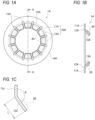
- FIGS. 1A to 1C show an example of an electrolytic corrosion prevention member applied when a rotating ring is an inner ring, as an electrolytic corrosion prevention member according to the present disclosure.
- FIG. 1A is a plan view thereof
- FIG. 1B is a cross-sectional view taken along a line A-A in FIG. 1A
- FIG. 1C is an enlarged view showing a bent portion between an annular portion and an elastic portion in FIG. 1B
- FIG. 2 is a cross-sectional view showing an example of a bearing unit according to the present disclosure provided with the electrolytic corrosion prevention member shown in FIGS. 1A to 1C .
- an electrolytic corrosion prevention member 1A for inner ring rotation includes a spring plate 10A including an annular portion 11A and a plurality of elastic portions 13A that are bent at an inner diameter side end portion 12A of the annular portion 11A and that extend in a radial shape toward the center of the annular portion 11A.
- a spring plate 10A including an annular portion 11A and a plurality of elastic portions 13A that are bent at an inner diameter side end portion 12A of the annular portion 11A and that extend in a radial shape toward the center of the annular portion 11A.
- the elastic portion 13A is mounted on a bearing unit 100A, the elastic portion 13A is bent toward the right side in the figure in a manner of facing an inner ring 52 of a rolling bearing 50.
- notches 15A are formed on both sides of the bent portion of the elastic portion 13A with the annular portion 11A to maintain the bent state of the elastic portion 13A.
- the spring plate 10A is entirely made of a thin plate made of a conductive material such as metal.
- a conductive material such as metal
- stainless steel is preferable because stainless steel is easy to process and is less prone to rust.
- a soft conductive member 20 is mounted on the surface of each elastic portion 13A on the side facing the inner ring 52 of the rolling bearing 50, and the spring plate 10A and the soft conductive member 20 constitute the electrolytic corrosion prevention member 1A.
- the soft conductive member 20 is mounted on the elastic portion 13A using the adhesive.
- the soft conductive member 20 is obtained by a soft base material being mixed with or supported on the conductive material.
- the soft base material include porous materials such as paper, cloth, and non-woven fabric, and resin sheets.
- the conductive material include metal fibers, pulverized materials, and powders of silver, copper, gold, aluminum, and stainless steel, and conductive carbon fibers, pulverized materials, and powders.
- a commercially available product called a "conductive sheet" or the like can also be used as the soft conductive member.
- the soft conductive member is made of, among the materials, at least one selected from resin-impregnated non-woven fabrics, non-woven fabrics, resin-impregnated woven fabrics, woven fabrics, resin-impregnated soft porous bodies such as sponges, and soft porous bodies such as sponges
- a bending angle ⁇ between the annular portion 11A and the elastic portion 13A is appropriately set according to a length (L) of the elastic portion 13A and the size of the soft conductive member 20 such that the soft conductive member 20 abuts against a side surface 52a of the inner ring 52 of the rolling bearing 50.
- the biasing force of the soft conductive member 20 to the side surface 52a of the inner ring 52 of the rolling bearing 50 can be adjusted.
- the biasing force can be strengthened, and conversely, by increasing the bending angle ⁇ , the biasing force can be weakened.
- the planar shape of the soft conductive member 20 is not limited, and may be a rectangular shape in addition to the fan shape shown in FIG. 1A . A plurality of small pieces may be used.
- the electrolytic corrosion prevention member 1A shown in FIGS. 1A to 1C is mounted on the rolling bearing 50 to constitute the bearing unit 100A.
- the rolling bearing 50 there is no limit to the rolling bearing 50, and a plurality of rolling elements (balls) 53 are held between an outer ring 51 and an inner ring 52 in a manner of rolling freely by a retainer 54, and are lubricated with a lubricating oil or a grease composition.
- the rotating ring is the inner ring 52, into which a shaft 60 directly connected to a motor (not shown) is fitted.
- the outer ring 51 is a fixed ring and is fixed to a housing 70.
- the annular portion 11A of the electrolytic corrosion prevention member 1A is pressed against the side surface of the outer ring 51 via a conductive spacer 30 by a conductive pressing member 80.
- the spacer 30 may have a thickness in consideration of the pressing amount of the spring plate 10A, the thickness of the soft conductive member 20, and the like.
- the annular portion 11A of the electrolytic corrosion prevention member 1A may directly abut against the side surface of the outer ring 51 without providing the spacer 30.
- the electrolytic corrosion prevention member 1A is mounted on the housing 70 such that the soft conductive member 20 abuts against the side surface 52a of the inner ring 52.
- the annular portion 11A of the spring plate 10A is in electrical contact with the side surface of the outer ring 51 via the conductive spacer 30, and is also in electrical contact with the conductive pressing member 80.
- the current from the shaft 60 flows from the soft conductive member 20 to the elastic portion 13A and the annular portion 11A of the spring plate 10A through the inner ring 52, and flows to the housing 70 via an outer peripheral end surface 14A of the annular portion 11A, the pressing member 80, the spacer 30, and the outer ring 51. Therefore, no current is applied inside the bearing, and the rolling bearing 50 does not suffer from electrolytic corrosion.
- the outer ring 51 Since the outer ring 51 has a large contact area with the housing 70, the current flowing through the outer ring 51 does not pass through the rolling element 53 and flows into the housing 70.
- the outer peripheral end surface 14A of the annular portion 11A and the spacer 30 abut against the housing 70.
- the outer peripheral end surface 14A and the spacer 30 may be held between the outer ring 51 and the pressing member 80 without abutting against the housing 70. In this case, the current flowing through the annular portion 11A flows to the housing 70 via the outer ring 51 and the pressing member 80.
- annular portion 11A of the electrolytic corrosion prevention member 1A may be directly pressed against the side surface of the outer ring 51 via the conductive spacer 30 without providing the pressing member 80, and may be fixed in a manner of abutting against the housing 70.
- the side surface 52a of the inner ring 52 is in contact with the soft conductive member 20, the side surface 52a of the inner ring 52 is not damaged, and the rotation torque of the inner ring 52 can be prevented from decreasing.
- the base material of the soft conductive member 20 is a porous body and has the oil absorption property and the oil retention property, oil is easily discharged between the adjacent spring plates 10A when the shaft rotates, and the oil film is less likely to form. Therefore, the conductivity is good even when the soft conductive member 20 is used in oil.
- the base material of the soft conductive member 20 as a porous body, the friction coefficient can be reduced even when the soft conductive member 20 is used in an environment other than the oil environment, and a reduction in the rotation torque of the inner ring 52 can be prevented.
- the spring plate 10A of the electrolytic corrosion prevention member 1A is a thin plate, and an increase in space of the bearing unit 100A can be minimized. Since there is no limitation on the rolling bearing 50 and there is no need to perform any processing, the rolling bearing 50 can be applied to the existing rolling bearing, and the versatility is fairly high.
- the spring plate 10A is entirely made of a bent thin plate and is an elastic member, by pressing the annular portion 11A of the electrolytic corrosion prevention member 1A toward the outer ring 51, the elastic force due to the pressing acts on the elastic portion 13A, the elastic portion 13A is pushed apart such that the bending angle ⁇ shown in FIG. 1C becomes larger, and the entire elastic portion 13A moves toward the rolling bearing 50. Accordingly, the portion of the soft conductive member 20 that is away from the side surface 52a of the inner ring 52 in FIG. 2 also moves toward the rolling bearing 50, and almost the entire soft conductive member 20 comes into contact with the side surface 52a of the inner ring 52.
- FIGS. 4A and 4B are views showing an electrolytic corrosion prevention member for outer ring rotation, in which FIG. 4A is a plan view thereof, and FIG. 4B is a cross-sectional view taken along a line A-A in FIG. 4A .
- FIG. 5 shows a bearing unit provided with the electrolytic corrosion prevention member shown in FIGS. 4A and 4B .
- an electrolytic corrosion prevention member 1B for outer ring rotation includes a spring plate 10B including an annular portion 11B and a plurality of elastic portions 13B that are bent at an outer diameter side end portion 12B of the annular portion 11B and that extend in a radial shape from the center of the annular portion 11B toward the outer periphery.
- a spring plate 10B including an annular portion 11B and a plurality of elastic portions 13B that are bent at an outer diameter side end portion 12B of the annular portion 11B and that extend in a radial shape from the center of the annular portion 11B toward the outer periphery.
- Arc-shaped notches 15B are formed on both sides of the bent portion of the elastic portion 13B with the annular portion 11B.
- the soft conductive member 20 is mounted on the surface of each elastic portion 13B on the side facing the outer ring 51 of the rolling bearing 50, and the spring plate 10B and the soft conductive member 20 constitute the electrolytic corrosion prevention member 1B.
- the soft conductive member 20 is the same as the electrolytic corrosion prevention member 1A described above, and the description thereof is omitted.
- the bearing unit 100B is provided with the electrolytic corrosion prevention member 1B.
- the inner ring 52 is fixed to a fixing member 75, and the outer ring 51 is provided with a rotating member 65. Therefore, the electrolytic corrosion prevention member 1B is mounted on the fixing member 75 such that the soft conductive member 20 abuts against the side surface 51a of the outer ring 51.
- the current from a motor (not shown) that drives the rotating member 65 flows to the outer ring 51
- the current flows from the soft conductive member 20 to the elastic portion 13B and the annular portion 11B of the spring plate 10B through the outer ring 51, and flows to the fixing member 75 via an inner peripheral end surface 14B of the annular portion 11B, the pressing member 80, the spacer 30, and the inner ring 52. Therefore, no current is applied inside the bearing, and the rolling bearing 50 does not suffer from electrolytic corrosion.
- the electrolytic corrosion of the rolling bearing 50 can be more effectively prevented by pressing the annular portion 11B of the electrolytic corrosion prevention member 1B toward the inner ring 52 by the pressing member 80 and increasing the contact area between the soft conductive member 20 and the side surface 51a of the outer ring 51.
- the annular portion 11B of the electrolytic corrosion prevention member 1B may also directly abut against the side surface of the inner ring 52 without providing the spacer 30.
- the inner peripheral end surface 14B of the annular portion 11B and the spacer 30 may abut against the fixing member 75 or may be held between the inner ring 52 and the pressing member 80 without abutting against the fixing member 75.
- FIG. 7 shows a case in which an electrolytic corrosion prevention member is mounted on a bearing unit whose rotating ring is an inner ring, similarly to the first embodiment.
- the shaft 60 which is a rotating member to which the inner ring 52 is fitted, is formed with a stepped surface 60c having a smaller diameter than a fitting surface 60b to which the inner ring 52 is fitted.
- the soft conductive member 20 of the spring plate 10A is mounted on the surface of the elastic portion 13A facing the shaft 60 in the axial direction, specifically, on a side surface 60a between the fitting surface 60b to which the inner ring 52 is fitted and the stepped surface 60c, by elastically deforming the elastic portion 13A. Therefore, the soft conductive member 20 can abut against the side surface 60a of the shaft 60.
- the soft conductive member 20 of the electrolytic corrosion prevention member 1A is mounted on the housing 70 in a manner of abutting against the side surface 60a of the shaft 60.
- the annular portion 11A of the spring plate 10A is in electrical contact with the side surface of the outer ring 51 via the conductive spacer 30, and is also in electrical contact with the end surface of a flange portion 71 of the housing 70.
- the current from the shaft 60 flows from the soft conductive member 20 to the elastic portion 13A and the annular portion 11A of the spring plate 10A through the side surface 60a of the shaft 60, and flows to the housing 70 via an outer peripheral end surface 14A of the annular portion 11A, the spacer 30, and the outer ring 51 or flows directly to the housing 70. Therefore, no current is applied inside the bearing, and the rolling bearing 50 does not suffer from electrolytic corrosion.
- the electrolytic corrosion prevention member 1A is not in contact with the side surface 52a of the inner ring 52. Therefore, the design freedom of the rolling bearing, such as the attachment of the snap ring, can be improved.
- the electrolytic corrosion prevention member and the rolling bearing are separated from each other in terms of position, the lubrication environments thereof can be separately controlled. For example, it is possible to place only the electrolytic corrosion prevention member in the dry environment, or to increase or decrease the amount of oil lubrication between the electrolytic corrosion prevention member and the rolling bearing.
- the position where the soft conductive member 20 is in contact with the side surface 60a of the shaft 60 has a smaller diameter than the position where the soft conductive member 20 is in contact with the side surface 52a of the inner ring 52 as shown in FIG. 1 . Therefore, the circumferential speed of the side surface 60a of the shaft 60 can be reduced, and the generation of the abrasion powder and drag loss can be further reduced.
- the shaft 60 may be provided with a flange portion 62 that protrudes from the fitting surface 60b toward the outer diameter side, and the soft conductive member 20 may abut against the side surface 60a of the flange portion 62.
- FIG. 9 shows a case in which an electrolytic corrosion prevention member is mounted on a bearing unit whose rotating ring is an outer ring, similarly to the second embodiment.
- the rotating member 65 to which the outer ring 51 is fitted has a stepped surface 65c having a larger diameter than a fitting surface 65b to which the outer ring 51 is fitted.
- the soft conductive member 20 of the spring plate 10B is mounted on the surface of the elastic portion 13B facing the rotating member 65 in the axial direction, specifically, on a side surface 65a between the fitting surface 65b to which the outer ring 51 is fitted and the stepped surface 65c, by elastically deforming the elastic portion 13B. Therefore, the soft conductive member 20 can abut against the side surface 65a of the rotating member 65.
- the soft conductive member 20 of the electrolytic corrosion prevention member 1B is mounted on the rotating member 65 in a manner of being abutting against the side surface 65a of the rotating member 65.
- the annular portion 11B of the spring plate 10B is in electrical contact with the side surface of the inner ring 52 via the conductive spacer 30, and is also in electrical contact with the end surface of a flange portion 76 of the fixing member 75.
- the current from the motor (not shown) that drives the rotating member 65 flows from the soft conductive member 20 to the elastic portion 13B and the annular portion 11B of the spring plate 10B through the side surface 65a of the rotating member 65, and flows to the fixing member 75 via the inner peripheral end surface 14B of the annular portion 11B, the spacer 30, and the inner ring 52 or flows directly to the fixing member 75. Therefore, no current is applied inside the bearing, and the rolling bearing 50 does not suffer from electrolytic corrosion.
- the electrolytic corrosion prevention member 1B is not in contact with the side surface 51a of the outer ring 51. Therefore, the design freedom of the rolling bearing, such as the attachment of the snap ring, can be improved.
- the electrolytic corrosion prevention member and the rolling bearing are separated from each other in terms of position, the lubrication environments thereof can be separately controlled. For example, it is possible to place only the electrolytic corrosion prevention member in the dry environment, or to increase or decrease the amount of oil lubrication between the electrolytic corrosion prevention member and the rolling bearing.
- the rotating member 65 may be provided with a flange portion 67 that protrudes from the fitting surface 65b toward the inner diameter side, and the soft conductive member 20 may abut against the side surface 65a of the flange portion 67.
- the position where the soft conductive member 20 is in contact with the side surface 65a of the rotating member 65 has a smaller diameter than the position where the soft conductive member 20 is in contact with the side surface 51a of the outer ring 51 as shown in FIG. 6 . Therefore, the circumferential speed of the side surface 65a of the rotating member 65 can be reduced, and the generation of the abrasion powder and drag loss can be further reduced.
- the plurality of elastic portions 13A and 13B of the spring plates 10A and 10B are bent toward the rotating ring.
- the plurality of elastic portions 13A and 13B may also be formed flush with the annular portions 11A and 11B without being bent at the inner diameter side end portion 12A and the outer diameter side end portion 12B.
- the annular portion 11A and the elastic portion 13A are linearly continuous in the side view.
- the electrolytic corrosion prevention member 1A can be manufactured at low cost, and the spring plate 10A and the soft conductive member 20 can be bonded together easily.
- the spring plate includes a plurality of elastic portions extending in a radial shape toward the center of the annular portion.
- the spring plate may include one elastic portion extending toward the center of the annular portion.
Landscapes
- Engineering & Computer Science (AREA)
- General Engineering & Computer Science (AREA)
- Mechanical Engineering (AREA)
- Ocean & Marine Engineering (AREA)
- Rolling Contact Bearings (AREA)
- Sealing Of Bearings (AREA)
- Mounting Of Bearings Or Others (AREA)
- Prevention Of Electric Corrosion (AREA)
Applications Claiming Priority (2)
| Application Number | Priority Date | Filing Date | Title |
|---|---|---|---|
| JP2023180999 | 2023-10-20 | ||
| JP2024028494A JP7817301B2 (ja) | 2023-10-20 | 2024-02-28 | 転がり軸受用電食防止部材及び電食防止転がり軸受ユニット |
Publications (1)
| Publication Number | Publication Date |
|---|---|
| EP4542066A1 true EP4542066A1 (de) | 2025-04-23 |
Family
ID=91620457
Family Applications (1)
| Application Number | Title | Priority Date | Filing Date |
|---|---|---|---|
| EP24183257.5A Pending EP4542066A1 (de) | 2023-10-20 | 2024-06-20 | Element zur verhinderung elektrolytischer korrosion für ein wälzlager und einheit zur verhinderung elektrolytischer korrosion |
Country Status (5)
| Country | Link |
|---|---|
| US (1) | US12607230B2 (de) |
| EP (1) | EP4542066A1 (de) |
| JP (2) | JP7817301B2 (de) |
| KR (1) | KR20250057613A (de) |
| CN (1) | CN119860403A (de) |
Citations (9)
| Publication number | Priority date | Publication date | Assignee | Title |
|---|---|---|---|---|
| JP2002146568A (ja) | 2000-11-06 | 2002-05-22 | Tsurumi Mfg Co Ltd | 水中回転機械の電食防止装置 |
| DE10152360B4 (de) * | 2001-03-24 | 2005-02-24 | Karstädt, Lutz | Strom-Schutz-Scheibe |
| JP2011135722A (ja) | 2009-12-25 | 2011-07-07 | Nsk Ltd | 車輪駆動装置用電食防止ユニットおよび車輪駆動装置 |
| JP2011135720A (ja) | 2009-12-25 | 2011-07-07 | Nsk Ltd | 車輪駆動装置用電食防止ユニットおよび車輪駆動装置 |
| JP2012097856A (ja) * | 2010-11-04 | 2012-05-24 | Daikin Industries Ltd | 軸受 |
| DE102015223509A1 (de) * | 2015-11-27 | 2017-03-02 | Schaeffler Technologies AG & Co. KG | Schutzvorrichtung mit elektrischer Leitfähigkeit |
| US10253818B1 (en) * | 2017-12-11 | 2019-04-09 | Schaefler Technologies Ag & Co. Kg | Bearing with electrical shunt |
| JP2020127257A (ja) | 2019-02-01 | 2020-08-20 | 株式会社日立インダストリアルプロダクツ | 回転電機、および、これを備えたダンプトラック |
| US20230261553A1 (en) * | 2022-02-17 | 2023-08-17 | Aktiebolaget Skf | Electrical machine with a conductive sleeve |
Family Cites Families (10)
| Publication number | Priority date | Publication date | Assignee | Title |
|---|---|---|---|---|
| JPH048820U (de) | 1990-05-14 | 1992-01-27 | ||
| JP2532147Y2 (ja) * | 1992-11-27 | 1997-04-09 | 東洋シール工業株式会社 | 軸受用密封装置 |
| JP4562271B2 (ja) * | 2000-11-06 | 2010-10-13 | 株式会社鶴見製作所 | 水中回転機械の電食防止装置 |
| JP6229414B2 (ja) * | 2013-09-30 | 2017-11-15 | 株式会社富士通ゼネラル | 電動機 |
| DE102017106695B3 (de) * | 2017-03-29 | 2018-04-19 | Schaeffler Technologies AG & Co. KG | Wälzlager mit integrierter Stromableitfunktion |
| DE102017113810B4 (de) * | 2017-06-22 | 2021-10-21 | Schaeffler Technologies AG & Co. KG | Potentialausgleichseinrichtung und Mechanikanordnung |
| DE102018115732A1 (de) * | 2018-06-29 | 2020-01-02 | Schaeffler Technologies AG & Co. KG | Wälzlager mit integrierter Stromableitfunktion |
| IT202000005578A1 (it) | 2020-03-17 | 2021-09-17 | Skf Ab | Assieme conduttivo ad attrito ridotto per cuscinetti |
| IT202000012151A1 (it) * | 2020-05-25 | 2021-11-25 | Skf Ab | Assieme combinato di isolante e conduttore per cuscinetti con conduttore bloccato con rebbio |
| JP2025021505A (ja) * | 2023-08-01 | 2025-02-14 | Ntn株式会社 | 電食防止通電カバーおよび転がり軸受 |
-
2024
- 2024-02-28 JP JP2024028494A patent/JP7817301B2/ja active Active
- 2024-06-18 KR KR1020240078903A patent/KR20250057613A/ko active Pending
- 2024-06-18 US US18/746,941 patent/US12607230B2/en active Active
- 2024-06-20 EP EP24183257.5A patent/EP4542066A1/de active Pending
- 2024-06-20 CN CN202410800507.9A patent/CN119860403A/zh active Pending
-
2025
- 2025-12-08 JP JP2025239457A patent/JP7817493B1/ja active Active
Patent Citations (9)
| Publication number | Priority date | Publication date | Assignee | Title |
|---|---|---|---|---|
| JP2002146568A (ja) | 2000-11-06 | 2002-05-22 | Tsurumi Mfg Co Ltd | 水中回転機械の電食防止装置 |
| DE10152360B4 (de) * | 2001-03-24 | 2005-02-24 | Karstädt, Lutz | Strom-Schutz-Scheibe |
| JP2011135722A (ja) | 2009-12-25 | 2011-07-07 | Nsk Ltd | 車輪駆動装置用電食防止ユニットおよび車輪駆動装置 |
| JP2011135720A (ja) | 2009-12-25 | 2011-07-07 | Nsk Ltd | 車輪駆動装置用電食防止ユニットおよび車輪駆動装置 |
| JP2012097856A (ja) * | 2010-11-04 | 2012-05-24 | Daikin Industries Ltd | 軸受 |
| DE102015223509A1 (de) * | 2015-11-27 | 2017-03-02 | Schaeffler Technologies AG & Co. KG | Schutzvorrichtung mit elektrischer Leitfähigkeit |
| US10253818B1 (en) * | 2017-12-11 | 2019-04-09 | Schaefler Technologies Ag & Co. Kg | Bearing with electrical shunt |
| JP2020127257A (ja) | 2019-02-01 | 2020-08-20 | 株式会社日立インダストリアルプロダクツ | 回転電機、および、これを備えたダンプトラック |
| US20230261553A1 (en) * | 2022-02-17 | 2023-08-17 | Aktiebolaget Skf | Electrical machine with a conductive sleeve |
Also Published As
| Publication number | Publication date |
|---|---|
| CN119860403A (zh) | 2025-04-22 |
| JP7817301B2 (ja) | 2026-02-18 |
| JP2026034503A (ja) | 2026-02-27 |
| US20250129821A1 (en) | 2025-04-24 |
| KR20250057613A (ko) | 2025-04-29 |
| JP2025070925A (ja) | 2025-05-02 |
| JP7817493B1 (ja) | 2026-02-18 |
| US12607230B2 (en) | 2026-04-21 |
Similar Documents
| Publication | Publication Date | Title |
|---|---|---|
| KR100491692B1 (ko) | 회전베어링 | |
| JPH1130239A (ja) | 電食防止転がり軸受 | |
| WO1989002543A1 (fr) | Roulement a rouleaux electrique | |
| EP4542066A1 (de) | Element zur verhinderung elektrolytischer korrosion für ein wälzlager und einheit zur verhinderung elektrolytischer korrosion | |
| EP4542067A1 (de) | Element zur verhinderung elektrolytischer korrosion für ein wälzlager und einheit zur verhinderung elektrolytischer korrosion | |
| JP7727033B2 (ja) | 転がり軸受用電食防止部材及び電食防止転がり軸受ユニット | |
| JP2007255637A (ja) | 転がり軸受 | |
| EP4715231A1 (de) | Wellenerdungselement für wälzlager und wälzlagereinheit | |
| EP4715232A1 (de) | Wellenerdungselement für wälzlager und wälzlagereinheit | |
| JP2001153145A (ja) | 密封形転がり軸受 | |
| JPH11264421A (ja) | 転がり軸受用アダプタ | |
| JP2026058293A (ja) | 転がり軸受用軸接地部材及び転がり軸受ユニット | |
| CN216278471U (zh) | 一种车用压缩机及其分体式轴套 | |
| JP2026058294A (ja) | 転がり軸受用軸接地部材及び転がり軸受ユニット | |
| JP4178803B2 (ja) | 振動モータ一体型軸受ユニット | |
| KR101950168B1 (ko) | 전기 모터 | |
| EP4068587B1 (de) | Elektrische drehmaschine | |
| JPH07119737A (ja) | 軸受装置 | |
| US20260039078A1 (en) | Conductive structural body and conduction method | |
| JP3256420B2 (ja) | スラスト軸受 | |
| JP2917414B2 (ja) | 軸流ファンモータ | |
| JP2005083442A (ja) | 通電軸受 | |
| JP2025017088A (ja) | 通電ユニット及び電動機 | |
| CN121569129A (zh) | 谐波减速器 | |
| JP2023184282A (ja) | ラジアル軸受 |
Legal Events
| Date | Code | Title | Description |
|---|---|---|---|
| PUAI | Public reference made under article 153(3) epc to a published international application that has entered the european phase |
Free format text: ORIGINAL CODE: 0009012 |
|
| STAA | Information on the status of an ep patent application or granted ep patent |
Free format text: STATUS: THE APPLICATION HAS BEEN PUBLISHED |
|
| AK | Designated contracting states |
Kind code of ref document: A1 Designated state(s): AL AT BE BG CH CY CZ DE DK EE ES FI FR GB GR HR HU IE IS IT LI LT LU LV MC ME MK MT NL NO PL PT RO RS SE SI SK SM TR |
|
| STAA | Information on the status of an ep patent application or granted ep patent |
Free format text: STATUS: REQUEST FOR EXAMINATION WAS MADE |
|
| 17P | Request for examination filed |
Effective date: 20251017 |