EP4542500A1 - Procédé, appareil, support de stockage, dispositif et produit de programme pour le traitement d'images - Google Patents
Procédé, appareil, support de stockage, dispositif et produit de programme pour le traitement d'images Download PDFInfo
- Publication number
- EP4542500A1 EP4542500A1 EP24204375.0A EP24204375A EP4542500A1 EP 4542500 A1 EP4542500 A1 EP 4542500A1 EP 24204375 A EP24204375 A EP 24204375A EP 4542500 A1 EP4542500 A1 EP 4542500A1
- Authority
- EP
- European Patent Office
- Prior art keywords
- texture
- mesh
- stylized
- scene
- panorama
- Prior art date
- Legal status (The legal status is an assumption and is not a legal conclusion. Google has not performed a legal analysis and makes no representation as to the accuracy of the status listed.)
- Pending
Links
Images


Classifications
-
- G—PHYSICS
- G06—COMPUTING OR CALCULATING; COUNTING
- G06T—IMAGE DATA PROCESSING OR GENERATION, IN GENERAL
- G06T15/00—Three-dimensional [3D] image rendering
- G06T15/06—Ray-tracing
-
- G—PHYSICS
- G06—COMPUTING OR CALCULATING; COUNTING
- G06T—IMAGE DATA PROCESSING OR GENERATION, IN GENERAL
- G06T15/00—Three-dimensional [3D] image rendering
- G06T15/04—Texture mapping
-
- G—PHYSICS
- G06—COMPUTING OR CALCULATING; COUNTING
- G06T—IMAGE DATA PROCESSING OR GENERATION, IN GENERAL
- G06T11/00—Two-dimensional [2D] image generation
- G06T11/10—Texturing; Colouring; Generation of textures or colours
-
- G—PHYSICS
- G06—COMPUTING OR CALCULATING; COUNTING
- G06T—IMAGE DATA PROCESSING OR GENERATION, IN GENERAL
- G06T15/00—Three-dimensional [3D] image rendering
- G06T15/005—General purpose rendering architectures
-
- G—PHYSICS
- G06—COMPUTING OR CALCULATING; COUNTING
- G06T—IMAGE DATA PROCESSING OR GENERATION, IN GENERAL
- G06T17/00—Three-dimensional [3D] modelling for computer graphics
- G06T17/20—Finite element generation, e.g. wire-frame surface description, tesselation
- G06T17/205—Re-meshing
-
- G—PHYSICS
- G06—COMPUTING OR CALCULATING; COUNTING
- G06T—IMAGE DATA PROCESSING OR GENERATION, IN GENERAL
- G06T19/00—Manipulating three-dimensional [3D] models or images for computer graphics
- G06T19/20—Editing of three-dimensional [3D] images, e.g. changing shapes or colours, aligning objects or positioning parts
-
- G—PHYSICS
- G06—COMPUTING OR CALCULATING; COUNTING
- G06T—IMAGE DATA PROCESSING OR GENERATION, IN GENERAL
- G06T3/00—Geometric image transformations in the plane of the image
- G06T3/40—Scaling of whole images or parts thereof, e.g. expanding or contracting
- G06T3/4053—Scaling of whole images or parts thereof, e.g. expanding or contracting based on super-resolution, i.e. the output image resolution being higher than the sensor resolution
-
- G—PHYSICS
- G06—COMPUTING OR CALCULATING; COUNTING
- G06T—IMAGE DATA PROCESSING OR GENERATION, IN GENERAL
- G06T5/00—Image enhancement or restoration
- G06T5/20—Image enhancement or restoration using local operators
- G06T5/30—Erosion or dilatation, e.g. thinning
-
- G—PHYSICS
- G06—COMPUTING OR CALCULATING; COUNTING
- G06T—IMAGE DATA PROCESSING OR GENERATION, IN GENERAL
- G06T7/00—Image analysis
- G06T7/10—Segmentation; Edge detection
- G06T7/13—Edge detection
-
- G—PHYSICS
- G06—COMPUTING OR CALCULATING; COUNTING
- G06T—IMAGE DATA PROCESSING OR GENERATION, IN GENERAL
- G06T7/00—Image analysis
- G06T7/50—Depth or shape recovery
-
- G—PHYSICS
- G06—COMPUTING OR CALCULATING; COUNTING
- G06T—IMAGE DATA PROCESSING OR GENERATION, IN GENERAL
- G06T2219/00—Indexing scheme for manipulating 3D models or images for computer graphics
- G06T2219/20—Indexing scheme for editing of 3D models
- G06T2219/2024—Style variation
Definitions
- the disclosure relates to the technical field of image processing, in particular to a method, an apparatus, a storage medium, a device and a program product for image processing.
- a typical three-dimensional scene representation may be a mesh.
- the current technology cannot automatically generate a stylized mesh texture mapping, and cannot ensure spatial consistency and mapping correctness, and is difficult to completely cover complex geometries in a real scene.
- Embodiments of the disclosure provide a method, an apparatus, a storage medium, a device and a program product for image processing, to automatically generate a stylized mesh texture mapping based on a prompt word provided by a user, meanwhile ensure spatial consistency, mapping correctness, and completely cover complex geometries in a real scene.
- an embodiment of the disclosure provides a method of processing image, where the method includes: obtaining a prompt word and a scene mesh, wherein the prompt word is text information that is provided by a user and represents a scene style, and the scene mesh is a three-dimensional mesh with a real texture generated based on a real scene reconstruction; generating a stylized panoramic texture map at a center position of the scene mesh based on the prompt word; projecting a texture of the stylized panoramic texture map to a visible area of the scene mesh to obtain a first stylized mesh texture mapping; and performing a spatial texture propagation processing on the first stylized mesh texture mapping to fill a non-visible area of the scene mesh to obtain a second stylized mesh texture mapping.
- an apparatus for image processing including:
- an embodiment of the disclosure provides a computer-readable storage medium storing a computer program, which is adapted to be loaded by a processor to perform the method of processing image according to any of the foregoing embodiments.
- an embodiment of the disclosure provides a terminal device, comprising a processor and a memory, wherein the memory stores a computer program, and the processor is configured to invoke the computer program stored in the memory to perform the method of processing image according to any of the foregoing embodiments.
- an embodiment of the disclosure provides a computer program product, comprising a computer program, which, when executed by a processor, implements the method of processing image according to any of the foregoing embodiments.
- the prompt word and the scene mesh are obtained, the prompt word is text information provided by the user and represents a scene style, and the scene mesh is a three-dimensional mesh with real texture generated based on the real scene reconstruction; a stylized panoramic texture map is generated at the center position of the scene mesh based on the prompt word; the texture of the stylized panoramic texture map is projected to the visible area of the scene mesh to obtain a first stylized mesh texture mapping; and the spatial texture propagation processing is performed on the first stylized mesh texture mapping to fill the non-visible area of the scene mesh to obtain the second stylized mesh texture mapping.
- the stylized mesh texture mapping can be automatically generated based on the prompt words provided by the user, meanwhile, the spatial consistency, the mapping correctness can be ensured and the complex geometric structure in the real-life scenario can be completely covered.
- the embodiments of the disclosure provide a method and an apparatus, a computer-readable storage medium, a terminal device and a program product for image processing. Specifically, the method of processing image in the embodiment of the disclosure may be performed by a terminal device or by a server.
- Embodiments of the disclosure may be applied to various application scenarios such as extended Reality (XR), Virtual Reality (VR), Augmented Reality (AR), Mixed Reality (MR), and the like.
- XR extended Reality
- VR Virtual Reality
- AR Augmented Reality
- MR Mixed Reality
- a virtual scene is a virtual scene displayed (or provided) when an application runs on a terminal or a server.
- the virtual scene is a simulated environment of a real world, or a virtual environment that is semi-simulated and semi-fictional, or a virtual environment that is purely fictional.
- the virtual scene is any of a two-dimensional virtual scene and a three-dimensional virtual scene.
- the virtual scene may be sky, land, ocean, etc., wherein the land includes environmental elements such as desert, city, etc.
- the virtual scene is a scene of a complete game logic of a virtual object, such as user control.
- Extended Reality is a concept including Virtual Reality (VR), Augmented Reality (AR), and Mixed Reality (MR), representing an environment in which a virtual world is connected to a real world, and a technology in which a user can interaction in real time with the environment.
- VR Virtual Reality
- AR Augmented Reality
- MR Mixed Reality
- Virtual Reality (VR) technology for creating and experiencing a virtual world, a calculation and generation of a virtual environment is a multi-source information
- the virtual reality mentioned herein includes at least visual perception, and may also include auditory perception, tactile perception, motion perception, even further including taste perception, olfactory perception, etc.
- implementing simulation of a fused, interactive three-dimensional dynamic visual and physical behavior of a virtual environment enabling a user to be immersed into a simulated virtual reality environment, and implementing an application of a plurality of virtual environments such as a map, a game, a video, an education, a medical, a simulation, a collaborative training, a sales, an assisted manufacturing, maintenance, and repair.
- Augmented Reality in a process of capturing an image by a camera, a camera pose parameter of a camera in a real world (or referred to as a three-dimensional world and a real world) is calculated in real time, and a virtual element technology is added on an image collect by a camera according to the camera pose parameter.
- Virtual elements include, but are not limited to: images, videos, and three-dimensional models.
- An objective of the AR technology is to sleeve the virtual world on the real world for interaction.
- MR Mixed Reality
- computer created sensory input may be adapted to changes in sensory input from a physical scenery.
- some electronic systems for presenting MR scenery may monitor orientation and/or position relative to physical scenery to enable virtual object to interaction with real objects (i.e., physical elements from physical scenery or representations thereof). For example, the system may monitor such that the virtual plant appears stationary relative to the physical building.
- Augmented Virtuality a simulated scenery where a computer created scenery or a virtual scenery incorporate at least one sensory input from a physical scenery.
- the one or more sensory inputs from the physical scenery may be representations of at least one feature of the physical scenery.
- a virtual object may exhibit a color of a physical element captured by one or more imaging sensors.
- the virtual object may exhibit characteristics consistent with actual weather conditions in the physical scenery, as identified via weather related imaging sensors and/or online weather data.
- an augmented reality forest may have virtual trees and structures, but animals may have features that are accurately reproduced from images taken on physical animals.
- a virtual field of view a region in a virtual environment that can be perceived by a user through a lens in a virtual reality device, and a field of view (FOV) of a virtual field of view is used to represent a perceived area.
- FOV field of view
- the virtual reality device the terminal implementing the virtual reality effect, may generally be provided as a form of glasses, a head mount display (HMD) and a contact lens, so as to realize visual perception and other forms of perception, and of course, the forms of the virtual reality device are not limited thereto, and may be further miniaturized or miniaturized as required.
- HMD head mount display
- contact lens a contact lens
- the virtual reality device described in this embodiment of the disclosure may include, but is not limited to, the following types:
- a computer end virtual reality (PCVR) device uses a PC end to perform related calculation and data output of a virtual reality function, and an external computer end virtual reality device uses data output by a PC end to achieve an effect of virtual reality.
- PCVR computer end virtual reality
- the mobile virtual reality device supports setting a mobile terminal (such as a smart phone) in various manners (for example, a head-mounted display provided with a special card slot), performing related calculation of the virtual reality function by the mobile terminal by connecting with the mobile terminal in a wired or wireless manner, and outputting data to the mobile virtual reality device, for example, viewing the virtual reality video through the APP of the mobile terminal.
- a mobile terminal such as a smart phone
- various manners for example, a head-mounted display provided with a special card slot
- the integrated machine virtual reality device is provided with a processor for performing related calculation of virtual functions, so that the integrated machine virtual reality device has independent virtual reality input and output functions, does not need to be connected with a PC end or a mobile terminal, and is high in use degree of freedom.
- UV is short for the texture mapping coordinate UVW (W coordinates are not commonly used), it definition the position coordinate information of each point on the mapping, the position of the gap between the point and the point is subjected to image smooth interpolation processing by the software, and is associated with the XYZ coordinates of the three-dimensional model, so as to determine the distribution position of the texture mapping; each three-dimensional model is composed of a plurality of faces, and the process of spreading the three-dimensional face on the two-dimensional canvas is called abduction UV.
- U and V represent horizontal and vertical coordinate axes, respectively.
- the UV map is a two-dimensional texture image.
- a real scene of a user is personalized and decorated by using a three-dimensional representation manner, for example, a user's bed in a displayed virtual scene image is changed into a game style bed by using a virtual reality device, a ceiling is changed into a starry style, and a rich and immersive experience may be provided.
- the three-dimensional representation may be a mesh.
- the AI texture mapping generation tool may be a plug-in for texture generation and painting using an AI model in free open-source three-dimensional graphical image software, the principle of which is to project a mapping from a view angle.
- the text-to-image model may be a text-to-image model based on a latent diffusion model (LDMs).
- LDMs latent diffusion model
- the text-to-image control model may be a neural network structure that controls the text-to-image model by adding additional conditions.
- the method for enhancing stable diffusion is provided, and the generated image can be closer to the input image by using input condition control in the text-to-image generation process
- the image texture generation algorithm cannot be applied to a mesh on a three-dimensional scene level, which mainly has three technical difficulties:
- the embodiments of the disclosure provide a method and an apparatus, a storage medium, a device and a program product for image processing, and can generate a stylized mesh texture mapping of a meaningful and attractive real-life scene based on a prompt word provided by a user, and meanwhile, the semantic consistency and the spatial coherence are maintained (for example, the furniture appears to be still a furniture type, but is presented in different texture styles).
- a top-down manner is used to perform texture generation on the scene mesh.
- the embodiments of the disclosure provide a method of image processing, and the method may be performed by a terminal or a server, or may be jointly performed by a terminal and a server.
- the embodiment of the disclosure is explained taking an example in which the method of processing image is executed by a terminal (terminal device).
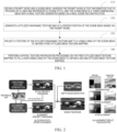
- FIG. 1 and FIG. 6 are schematic flowcharts of a method of processing image according to an embodiment of the disclosure.
- FIG. 2 to FIG. 5 and FIG. 7 to FIG. 8 are a schematic diagram of an application scenario of a method of processing image according to an embodiment of the disclosure.
- the method may be applied to a terminal device, and the terminal device may include any of an extended reality device, a virtual reality device, an augmented reality device, and a mixed reality device.
- the method includes:
- Step 110 Obtain a prompt word and a scene mesh, the prompt word being text information that is provided by a user and represents a scene style, and the scene mesh being a three-dimensional mesh with a real texture generated based on a real scene reconstruction.
- the prompt word P provided by the user may be obtained through user input or automatic identification technology, and the prompt word P may be text information.
- a real reconstructed scene mesh with a real texture is obtained by 3D scanning or image processing technology.
- Step 120 generate a stylized panoramic texture map at a center position of the scene mesh based on the prompt word .
- the stylized panoramic texture image may be obtained by performing texture stylization based on the scene of the panoramic view, specifically, by using the personalized processing of text driving in the panoramic view space, the stylized panoramic texture image with consistent scene height is achieved.
- the stylized panoramic texture map comprises a style priority panorama
- generate a stylized panoramic texture map at a center position of the scene mesh based on the prompt word comprises:
- the generating the style priority panorama at the center position of the scene mesh based on the prompt word comprises:
- the prompt word P, the true color (RGB) map I P and the depth map D are processed by using a pre-trained diffusion model to generate a seamless and high-resolution style priority panorama, and the style priority panorama is determined as a stylized panoramic texture map.
- the true color map refers to an image presented in a real color, usually an image captured by a color camera or a VCR, these images include detail information such as color and texture of an object in the scene, and visual perception of a real scene may be provided.
- the depth map refers to an image with depth information, and is usually obtained by a depth sensor (for example, a ToF camera, a structured light camera, a stereo vision camera, etc. ); in the embodiment of the disclosure, the depth map may be directly obtained through mesh rendering at a moment of a known scene mesh.
- the depth map may provide distance information of objects from the camera in the scene, typically represented in the form of grayscale images or color codes.
- the disclosure designs a generation solution from coarse to fine.
- the RGB map I P and the depth map D are used as input condition controls of the diffusion model (using the text-to-image control model technology) to generate a low-resolution initial style priority panorama Î S .
- I ⁇ S F c P ; D , ⁇ I P
- F C is a diffusion model with multiple condition control
- ⁇ ( I P )) is a soft edge (SoftEdge) map extracted with a pixel difference network (PiDiNet)
- P is a prompt word
- D is a depth map.
- a size of the low-resolution initial style priority panorama Î S may be 1024*512.
- the pixel difference network (PiDNet) is configured to perform effective edge detection.
- step 123 enlarging the initial style priority panorama by a predetermined magnification factor based on a super-resolution amplification technology to obtain the style priority panorama, wherein a resolution of the style priority panorama is greater than a resolution of the initial style priority panorama.
- the UNet structure is a convolutional neural network used for image segmentation, the UNet network is composed of a contraction path and an extension path, and a jump connection structure is provided between the contraction path and the network layer corresponding to the extension path.
- the panoramic texture generation solution described in step 120 can be widely applied to various applications requiring panoramic texture generation, such as game production, virtual reality, augmented reality and other scenes, which not only considers the color and shape of the texture, but also combines the prompt word and depth information provided by the user, can quickly and accurately generate high-quality panoramic texture, and improves the performance of related applications and user experience.
- applications requiring panoramic texture generation such as game production, virtual reality, augmented reality and other scenes, which not only considers the color and shape of the texture, but also combines the prompt word and depth information provided by the user, can quickly and accurately generate high-quality panoramic texture, and improves the performance of related applications and user experience.
- the stylized panoramic texture map comprises the style priority panorama and an alignment priority panorama
- the determining the stylized panoramic texture map based on the style priority panorama comprise:
- the generating the alignment priority panorama based on the prompt word, the true color map and the style priority panorama comprises :
- the performing texture mixing on the style priority panorama and the alignment priority panorama to generate the stylized panoramic texture map comprises:
- the diffusion model may be effectively guided to generate a texture that is substantially aligned with the scene mesh, but in the texture generation task of the scene level, due to the complex geometry of the real scene, the alignment of the initial generated texture often cannot meet the requirement.
- a double-path texture alignment scheme may also be used, and the double-path textures are mixed by respectively generating a double-path texture of the style priority panorama and the alignment priority panorama, and then using edge detection at a jump of the depth map as a reference, so as to obtain a stylized panoramic texture map.
- the style priority panorama is generated by the reference map
- alignment texture generation is performed based on the reference map and style information obtained by style extraction from the style priority panorama
- an aligned priority panorama is obtained
- the textures of the style priority panorama and the alignment priority panorama are mixed based on the first depth edge filter mask generated by the depth edge detection, to obtain a mixed panorama (stylized panoramic texture map).
- the aligned image can repair dislocation and keep style .
- Step 121 render a true color map and a depth map of a real scene at the center position of the scene mesh .
- Step 122 process the prompt word, the true color map and the depth map by using a pre-trained diffusion model to generate an initial style priority panorama .
- step 123 enlarging the initial style priority panorama by a predetermined magnification factor based on a super-resolution amplification technology to obtain the style priority panorama, wherein a resolution of the style priority panorama is greater than a resolution of the initial style priority panorama.
- step 121 to step 123 For specific implementations of step 121 to step 123, reference may be made to the specific description in the foregoing embodiments, and details are not described herein again.
- Step 124 generate an initial alignment priority panorama by inputting the prompt word, the true color map, the depth map and the style priority panorama into the diffusion model for processing .
- the prompt word, the true color (RGB) map, the depth map and the style priority panorama are used as input, and the initial alignment priority panorama is generated by using the diffusion model.
- the style information T (Is) extracted from the style priority panorama will be used as part of the condition control by using the image-to-image style control module.
- the disclosure performs denoising on the panoramic RGB map of the real world based on the edge detection algorithm, and then uses the condition control technology of the text-to-image control model to generate the initial alignment priority panorama Î A .
- I ⁇ A F c P ; C I P , T I S where F C is a diffusion model with multi-condition control; P is a prompt word;
- C (I p ) is an edge detection result obtained by performing edge detection on the true color map I p based on an edge detection algorithm, and is used for denoising the true color map I p ;
- T(Is) is style information extracted from the style priority panorama by using the image-to-image style control module, and is used for maintaining consistency of the style.
- the edge detection algorithm used in the embodiments of the disclosure is a method of detecting an edge by using a multi-level edge detection algorithm. For detecting edges or contours in an image.
- the basic idea of this algorithm is to first find an obvious edge in the image, and then determine the position and direction of the edge by calculating the gradient of the pixel in the image.
- the image-to-image style control module is a function module for controlling the style and semantics of the generated image area to follow the original image in the large-scale image diffusion model, and commonly used for controlling algorithms to generate new details that follow the original image details in tasks such as image enlargement and detail restoration .
- Step 125 enlarge the initial alignment priority panorama by a predetermined magnification factor based on a super-resolution amplification technology to obtain the alignment priority panorama, wherein a resolution of the alignment priority panorama is greater than a resolution of the initial alignment priority panorama.
- the initial alignment priority panorama Î A is enlarged to the same size as the style priority panorama based on a predetermined magnification factor (for example, three times) by using a super-resolution amplification algorithm, to obtain the alignment priority panorama Î AL .
- Step 126 generate a first depth edge filter mask based on an edge detection result at a jump of the depth map, wherein the first depth edge filter mask is configured to represent a pixel area in which the style priority panorama and the alignment priority panorama are mixed.
- the depth edge jump region may be detected from the depth map to generate the first depth edge filter mask, which may be configured to represent a pixel area in which the style priority panorama and the alignment priority panorama are mixed.
- the first depth edge filter mask may be configured to represent a pixel area in which the style priority panorama and the alignment priority panorama are mixed.
- a jump region is detected at the depth edge as a reference.
- a first depth edge filter mask is generated based on the edge detection result at the jump of the depth map by using an image processing algorithm.
- the first depth edge filter mask may be configured to indicate which pixel regions should be mixed, which pixel regions should be left intact.
- This step mainly identifies the depth edge by analyzing pixel value changes in the depth map.
- the depth edge corresponds to the contour or border of the object in the image, and the pixel values of these regions may change significantly.
- These depth edges may be detected and a first depth edge filter mask may be generated by setting appropriate thresholds.
- Step 127 mix textures of the style priority panorama and the alignment priority panorama using a Poisson image editing algorithm based on the first depth edge filter mask to obtain the stylized panoramic texture map.
- the texture on both sides of the depth edge may be mixed by using a Poisson image editing algorithm.
- the Poisson image editing method mainly satisfies a certain boundary condition, so that the gradient field of the two-dimensional function to be solved in the region are as similar as possible.
- the boundary condition herein means that the function value is equal to the value of the target image on the boundary.
- the prompt words "AAA...BBB... CCC... " described by the user are obtained; then a three-dimensional scene mesh with real texture generated based on the real scene is reconstructed; then a style priority panorama is generated at the center position of the scene mesh based the prompt words; then panoramic diffusion is performed to generate an alignment priority panorama; and then the style priority panorama and the alignment priority panorama are subjected to double-path texture alignment, thereby generating a high-definition stylized panoramic texture map.
- Step 130 project a texture of the stylized panoramic texture map to a visible area of the scene mesh to obtain a first stylized mesh texture mapping .
- the texture of the stylized panoramic texture map may be projected to the visible area of the three-dimensional scene mesh through the UV mapping in the panoramic space, to obtain the first stylized mesh texture mapping.
- step 130 may be implemented by step 131 to step 135, specifically:
- Step 131 obtain a two-dimensional texture image of the scene mesh and a texture coordinate corresponding to each pixel in the two-dimensional texture image.
- the two-dimensional texture image is a UV map.
- step 131 a UV map of the scene mesh and texture coordinates corresponding to each pixel in the UV map are obtained.
- This step may be implemented by a software tool or algorithm, for example, the 3D modeling tool may directly generate the UV map and the texture coordinates when creating the three-dimensional model.
- Step 132 compute a spatial coordinate of each pixel of the two-dimensional texture image in a three-dimensional space by an interpolation based on the two-dimensional texture image and the texture coordinate .
- the spatial coordinates of each pixel of the UV map in the three-dimensional space are computed by interpolation based on the UV map and the texture coordinates.
- the specific interpolation method may adopt methods such as gravity center interpolation.
- Step 133 compute a ray direction between each pixel of the two-dimensional texture image and a camera based on the spatial coordinate of each pixel of the two-dimensional texture image in the three-dimensional space, and mapping the ray direction onto the stylized panoramic texture map by an equidistant cylindrical projection.
- the ray direction between each pixel and the camera is computed, and the ray direction is mapped onto the stylized panoramic texture map through equidistant cylindrical projection.
- Step 134 determine visibility information of each pixel of the two-dimensional texture image under observation of the camera to generate a first visibility mask based on the visibility information, wherein the visibility information is configured to represent whether a spatial coordinate of each pixel of the two-dimensional texture image is visible when observed from a coordinate of a center position of the camera.
- Step 135 assign a panoramic color of the stylized panoramic texture map to a two-dimensional texture space based on the first visibility mask and the ray direction, to project a texture of the stylized panoramic texture map to the visible area of the scene mesh, to obtain the first stylized mesh texture mapping.
- the two-dimensional texture space is a UV space.
- the panoramic color of the stylized panoramic texture map is assigned to the UV space based on the first visibility mask and the ray direction.
- the panoramic color is assigned to the UV space based on the first visibility mask and the ray direction, and the operation of projecting the panoramic texture onto the three-dimensional mesh is completed.
- the specific assignment method may be designed according to actual needs.
- the panoramic color of the stylized panoramic texture map is assigned to the UV space based on the first visibility mask M init_ vis and the corresponding ray direction d, and the texture of the stylized panoramic texture map is projected to the visible area of the three-dimensional scene mesh to obtain the operation of the first stylized mesh texture mapping, to implement partial texture stylization of the scene, and improve the effect and quality of texture mapping.
- Step 140 perform spatial texture propagation processing on the first stylized mesh texture mapping to fill a non-visible area of the scene mesh to obtain a second stylized mesh texture mapping .
- the completion image may be obtained based on the spatial texture propagation of the multi-view panoramic view completion, specifically, the texture of the previous occlusion region is filled through the view completion algorithm under the panorama, to obtain the completion image. Then, filling the non-visible area in the completion image based on the spatial texture prediction network to obtain the second stylized mesh texture mapping, may be specifically: pre-learning from the current texture stylized map by using the spatial texture prediction network, and predicting a reasonable texture of the non-covered region of the texture.
- step 130 after the texture of the stylized panoramic texture map is projected to the visible area of the three-dimensional scene mesh to obtain the first stylized mesh texture mapping, some uncovered areas in the first stylized mesh texture mapping need to be filled.
- the disclosure proposes separate policies for regions of different visibility.
- panoramic viewing angle texture completion Panoramic Texture Inpainting
- step 140 may be implemented by step 141 to step 142, specifically:
- the performing panoramic viewing angle texture completion on the first stylized mesh texture mapping to obtain a completion image comprises :
- step 141 panoramic viewing angle texture completion is performed on the first stylized mesh texture mapping to obtain a completed image.
- step 141 panoramic viewing angle texture completion is performed on the first stylized mesh texture mapping to obtain a completed image.
- partial texture stylized filled mesh in the first stylized mesh texture mapping are provided, and then panoramic viewing angle texture completion is implemented in the panoramic space
- the panorama completion mask M inp is determined based on the new camera position.
- the first visibility mask M init_ vis of the UV space may be regarded as UV texture for multiplexing, and the panoramic image is rendered on the current viewpoint, and then the image is expanded and blurred to obtain the panoramic completion mask M inp .
- the initial completion image Î inp when the initial completion image Î inp is generated, factors such as a region in which the depth suddenly changes in the initial completion image, a small incident viewing angle (an incident view angle of the camera to the mesh surface in the initial completion image is less than a preset angle) or a too far surface point (the distance between the surface point of the corresponding mesh surface in the initial completion image and the camera is greater than a preset distance), and visibility of the perspective of the completion position camera are considered, thereby ensuring credible texture projection. Finally, the completed panoramic texture is assigned to the stylized UV texture resulting in a completed image, further filling the partially stylized scene.
- the initial completion image Î inp is not completely projected into the stylized UV texture, but only the trusted region is filtered through visibility information of the UV space.
- filtering may be performed by designing three UV spatial masks to ensure credible texture projection.
- the second depth edge overmask M dep _ edge may be used to filter an area with sudden depth change in the initial complement image Î inp , and the depth edge jump area may be detected from the depth map to generate the second depth edge overmask M dep _ edge .
- the security observation mask M safe _ view may be formed by filtering a small incident viewing angle (an incident view angle is less than a preset angle, for example, an incident view angle is less than 10 °) or a too far surface point (a distance between the surface point and the camera is greater than a preset distance, for example, a distance between the surface point and the camera is greater than 2.5m) in the initial completion image Î inp .
- the visibility test may be performed based on the camera view angle of the completion position to construct the second visibility mask M inp _ vis of the completion viewing angle, where the second visibility mask M inp _ vis may be constructed using the above formula (4).
- This design avoids view-based occlusion problems since all masks are built in the UV space rather than being built in a certain camera perspective or panoramic view.
- the panoramic texture of the initial completion image is assigned to the UV texture of the first stylized mesh texture mapping using the trusted mask M conf to obtain a completion image, further filling the partially stylized scene with more textures.
- Step 142 fill a non-visible area in the completion image by using a spatial texture prediction network to obtain a second stylized mesh texture mapping, wherein the non-visible area comprises at least one of the following: a fine geometric area and an occluded area.
- the filling a non-visible area in the completion image by using a spatial texture prediction network to obtain a second stylized mesh texture mapping comprises:
- the spatial coordinate x of all effective UV pixels and the real world color C R are provided to the spatial texture prediction network to predict the color.
- predicted color may be fused into the partially texture mesh by the accumulated visibility mask M accu , resulting in a fully stylized scene.
- a spatial texture prediction network may be designed in step 142, the target of the texture prediction being a learning style map from the partially stylized scene, and then smoothly prediction a reasonable texture of the non-visible area.
- a spatial texture prediction network F Imit a network input space coordinate x and a real world color C R from a partial texture scene are learned, and supervision of the L2 loss function is performed by using the currently visible stylized color Cs, as shown in the following formula (7):
- the spatial coordinate x of all valid UV pixels and the real world color C R are provided to the spatial texture prediction network to predict the target color ⁇ S .
- the predicted target color ⁇ S is fused to mesh of partial texture of completion image though the accumulated third visibility mask M accu to obtain the second stylized mesh texture mapping, and finally a fully stylized scene is generated.
- the third visibility mask M accu may be obtained by combining the first visibility mask M init _vis and all the second visibility mask M inp _ vis .
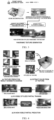
- a spatial texture prediction network is designed, as shown in the schematic diagram of the texture prediction result shown in FIG. 4 (a) , there is a pillow and a sheet in the reference image of the real scene provided in FIG. 4(a) , before texture prediction is performed on a completion image corresponding to the reference image, the black areas near the pillow, the cabinet and the like are not covered with colors, and after the texture prediction is performed, the original black areas in the image are covered with reasonable colors .
- the real world color C R of the real UV texture and the stylized color Cs of the stylized UV texture are mapped from the corresponding UV textures to the spatial coordinates x.
- the real world color C R of the real scene is input into the spatial texture prediction network, and the currently visible stylized color Cs is used to supervise the L2 loss function to obtain a supervised stylized map.
- the spatial texture propagation is carried out, the texture can be automatically and efficiently mapped to the three-dimensional scene mesh, and various complex occlusion and fine geometry conditions can be processed.
- partial texture stylization of the scene may also be implemented, thereby improving the effect and quality of texture mapping.
- the texture of the stylized panoramic texture map is first projected to the visible region of the scene mesh to obtain a first stylized mesh texture map, and then spatial texture propagation is performed on the partially texture stylized scene based on the stylized UV texture.
- the panoramic view angle completion is performed on the credible un-occluded area. Specifically, for different complemented viewpoints, the completion viewing angle visibility in the scene geometry is filtered based on the cameras at different completion positions, and then image completion is performed to obtain a completion image.
- the spatial texture prediction is performed on a tiny occluded region, in particular, in the training stage, a spatial texture prediction network F I mit , a network input space coordinate x, and a real world color C R from a partial texture scene are learned, and supervision of the L2 loss function is performed by using the currently visible stylized color Cs; and then the trained spatial texture prediction network is used to fill remaining fine geometric or complex occlusion regions in the completion image to obtain a second stylized mesh texture mapping.
- the method may further include step 150.
- Step 150 package a virtual window, a panoramic sky box, the second stylized mesh texture mapping and an original scene mesh to generate a target virtual scene, and displaying the target virtual scene .
- step 150 of the embodiment of the disclosure based on the virtual window of the personalized scene and the VR terminal immersive personalized application of the panoramic sky box, the target virtual scene with complete texture stylization is immersed in the head-mounted display device in an immersive manner, and the interactivity and immersion of the user and the virtual environment can be increased while the reality and visual effects are ensured, which significantly improves the VR terminal experience.
- step 150 may be implemented by the following step 151 to step 154.
- Step 151 create a virtual environment space based on the second stylized mesh texture mapping and the original scene mesh .
- the schematic diagram of the input material shown in FIG. 8 for example, the schematic diagram of the input material shown in FIG. 8 (a) .
- the scene material for example, the stylized bedroom scene and the transparent window
- the user-defined virtual environment space is created. It can also be operated according to the actual requirements of the user to realize the personalized virtual environment space.
- the virtual environment space is uploaded to a head mounted display (HMD) device for a virtual tour.
- HMD head mounted display
- the original scene mesh is a texture generated by the image acquisition device by acquiring a real scene.
- the original scene mesh does not contain real textures.
- Step 152 generate the virtual window in the virtual environment space.
- a transparent alpha mask value distribution may be made to the baked UV image according to user-defined window creation requirements, and a transparent virtual window is generated at the window position indicated in the window creation request.
- the window size, the window shape and the window position and the visual effect thereof in the scene need to be considered.
- the alpha mask of the UV space is generated using a manner similar to the previous completion mask. This can enable a window to be opened in the virtual environment space, so that the user can see the world outside the virtual environment space, enhance the immersion of the virtual environment, and also avoid the user's motion sickness in the immersive experience.
- the transparent window in the schematic diagram of the input material shown in FIG. 8 (a) may be generating the transparent window on a user-defined area after inputting the stylized bedroom scene.
- Step 153 create the panoramic sky box.
- the panoramic sky box may be generated by the sky-box function in the game engine.
- the design of the panoramic sky box may be selected by the user, for example, may be consistent with the scene style or form a sharp contrast with the scene style.
- a sky box function in a game engine may provide a plurality of sky box materials, determine a target sky box in response to a sky box material selection instruction of a user, and render the target sky box into a virtual environment space to create a panoramic sky box. This may enhance the spatial and immersion of the virtual environment.
- the target sky box is a sky box in the schematic diagram of the input material shown in FIG. 8 (a)
- the sky box is a sky box of the starry sky theme
- target sky box is rendered into the virtual environment space to create the panoramic sky box shown in FIG. 8 (b) .
- Step 154 package and render the second stylized mesh texture mapping, the original scene mesh, the virtual window, and the panoramic sky box to generate the target virtual scene, and displaying the target virtual scene.
- the generated second stylized mesh texture map, the original scene mesh, the virtual window, and the panoramic sky box may be packaged and rendered in the game engine to generate the target virtual scene.
- the panoramic sky box is used as the background, and the virtual window with the transparent UV texture is turned on at the same time, so that the effect of seeing the panoramic sky box outside the virtual environment space through the transparent virtual window can be achieved.
- the finally displayed target virtual scene will be a fully immersive virtual environment, allowing the user to freely roam in stylized spaces with a familiar scene structure but with a completely different appearance.
- the stylized scene is immersed in a bedroom by using a VR device, and in this stylized scenario, a user can experience observing a star sky scene in a stylized bedroom scene.
- the real scene can be converted into a stylized scene in a text driving mode, and the immersive roaming experience of 6DoF in the VR device is supported.
- the prompt word and the scene mesh are obtained, the prompt word is text information that is provided by a user and represents a scene style, and the scene mesh is a three-dimensional mesh with a real texture generated based on a real scene reconstruction; generating a stylized panoramic texture map at a center position of the scene mesh based on the prompt word ; projecting a texture of the stylized panoramic texture map to a visible area of the scene mesh to obtain a first stylized mesh texture mapping; and performing a spatial texture propagation processing on the first stylized mesh texture mapping to fill a non-visible area of the scene mesh to obtain a second stylized mesh texture mapping.
- the stylized mesh texture mapping can be automatically generated based on the prompt words provided by the user, meanwhile ensure spatial consistency, mapping correctness, and completely cover complex geometries in a real scene.
- FIG. 9 is a schematic structural diagram of an apparatus for image processing according to an embodiment of the disclosure.
- the apparatus for image processing 200 may include:
- the stylized panoramic texture map includes a style priority panorama
- the first processing unit 220 may be configured to: generate the style priority panorama at the center position of the scene mesh based on the prompt word; and determine the stylized panoramic texture map based on the style priority panorama.
- the first processing unit 220 may be configured to: render a true color map and a depth map of a real scene at the center position of the scene mesh; process the prompt word, the true color map and the depth map by using a pre-trained diffusion model to generate an initial style priority panorama ; and enlarge the initial style priority panorama by a predetermined magnification factor based on a super-resolution amplification technology to obtain the style priority panorama, wherein a resolution of the style priority panorama is greater than a resolution of the initial style priority panorama.
- the stylized panoramic texture map comprises the style priority panorama and an alignment priority panorama
- the first processing unit 220 may be further configured to: generate the alignment priority panorama based on the prompt word, the true color map and the depth map; and perform texture mixing on the style priority panorama and the alignment priority panorama to generate the stylized panoramic texture map .
- the first processing unit 220 when generating the alignment priority panorama based on the prompt word, the true color map and the style priority panorama, may be configured to: generate an initial alignment priority panorama by inputting the prompt word, the true color map, the depth map and the style priority panorama into the diffusion model for processing ; and enlarge the initial alignment priority panorama by a predetermined magnification factor based on a super-resolution amplification technology to obtain the alignment priority panorama, wherein a resolution of the alignment priority panorama is greater than a resolution of the initial alignment priority panorama.
- the first processing unit 220 when performing texture mixing on the style priority panorama and the alignment priority panorama to generate the stylized panoramic texture map, may be configured to: generate a first depth edge filter mask based on an edge detection result at a jump of the depth map, wherein the first depth edge filter mask is configured to represent a pixel area in which the style priority panorama and the alignment priority panorama are mixed; and mix textures of the style priority panorama and the alignment priority panorama using a Poisson image editing algorithm based on the first depth edge filter mask to obtain the stylized panoramic texture map.
- the second processing unit 230 may be configured to: obtain a two-dimensional texture image of the scene mesh and a texture coordinate corresponding to each pixel in the two-dimensional texture image; compute a spatial coordinate of each pixel of the two-dimensional texture image in a three-dimensional space by an interpolation based on the two-dimensional texture image and the texture coordinate; compute a ray direction between each pixel of the two-dimensional texture image and a camera based on the spatial coordinate of each pixel of the two-dimensional texture image in the three-dimensional space, and map the ray direction onto the stylized panoramic texture map by an equidistant cylindrical projection; determine visibility information of each pixel of the two-dimensional texture image under observation of the camera to generate a first visibility mask based on the visibility information, wherein the visibility information is configured to represent whether a spatial coordinate of each pixel of the two-dimensional texture image is visible when observed from a coordinate of a center position of the camera; and assign a panoramic color of the stylized panoramic texture map to a two-dimensional texture space
- the third processing unit 240 may be configured to: perform panoramic viewing angle texture completion on the first stylized mesh texture mapping to obtain a completion image; and fill a non-visible area in the completion image by using a spatial texture prediction network to obtain a second stylized mesh texture mapping, wherein the non-visible area comprises at least one of the following: a fine geometric area and an occluded area.
- the third processing unit 240 may be configured to: performing a dilation processing and a blurring processing on the first stylized mesh texture mapping to obtain a panoramic completion mask; process the prompt word, the first stylized mesh texture mapping, the depth map, and the panoramic completion mask by using an image completion model to generate an initial completion image ; obtain a second depth edge filter mask, a security observation mask, and a second visibility mask, wherein the second depth edge filter mask is configured to filter an area with sudden depth change in the initial completion image, the security observation mask is configured to filter an area in the initial completion image in which an incident viewing angle from the camera to a mesh surface is less than a preset angle and/or an area in the initial completion image in which a distance between a surface point of a corresponding mesh surface and the camera is greater than a preset distance, and the second visibility mask is configured to filter a visible pixel area in the initial completion image when observed from a coordinate of a center position
- the third processing unit 240 may be configured to: provide spatial coordinates and real world colors of all pixels in the two-dimensional texture image of the scene mesh to the spatial texture prediction network to predict a target color; obtain a third visibility mask by combining the first visibility mask and the second visibility mask; and fuse the predicted target color to the non-visible area in the completion image through the third visibility mask to obtain the second stylized mesh texture mapping .
- the apparatus for image processing 200 further includes: a fourth processing unit, configured to package a virtual window, a panoramic sky box, the second stylized mesh texture mapping and an original scene mesh to generate a target virtual scene, and displaying the target virtual scene .
- a fourth processing unit configured to package a virtual window, a panoramic sky box, the second stylized mesh texture mapping and an original scene mesh to generate a target virtual scene, and displaying the target virtual scene .
- the fourth processing unit is configured to: create a virtual environment space based on the second stylized mesh texture mapping and the original scene mesh; generate the virtual window in the virtual environment space; create the panoramic sky box; and package and render the second stylized mesh texture mapping, the original scene mesh, the virtual window, and the panoramic sky box to generate the target virtual scene, and display the target virtual scene.
- Each unit in the foregoing apparatus for image processing 200 may be implemented in whole or in part by software, hardware, or a combination thereof.
- the foregoing units may be embedded in or independent of a processor in the terminal device in a hardware form, or may be stored in a memory in the terminal device in a software form, so that the processor invokes and performs an operation corresponding to foregoing each unit.
- the apparatus for image processing 200 may be integrated in a terminal or a server provided with a storage and having an operation capability, or the apparatus for image processing 200 is the terminal or a server.
- the disclosure further provides a terminal device, including a memory and a processor, where the memory stores a computer program, and when the processor executes the computer program, the steps in the foregoing method embodiments are implemented.
- the virtual scene in the three-dimensional scene mesh may be constructed by using the modeling module 305; obtaining the prompt word and the scene mesh by using the detection module 301, the prompt word is text information that is provided by the user and represents the style of the scene, and the scene mesh is a three-dimensional mesh with a real texture generated based on the real scene reconstruction; generating a stylized panoramic texture map at a center position of the scene mesh based on the prompt word by using the control module 304; projecting a texture of the stylized panoramic texture map to a visible area of the scene mesh to obtain a first stylized mesh texture mapping; performing a spatial texture propagation processing on the first stylized mesh texture mapping to fill a non-visible area of the scene mesh to obtain a second stylized mesh texture mapping; and the virtual window and the panoramic sky box may be rendered to the second stylized mesh texture map to generate the target virtual scene.
- the graphical user interface may be displayed through the feedback module 302, and the graphical user interface may include a second stylized mesh texture mapping, or may include
- FIG. 11 is another schematic structural diagram of a terminal device according to an embodiment of the disclosure, and the terminal device 300 further includes a processor 310 having one or more processing cores, a memory 320 having one or more computer-readable storage media, and a computer program stored on the memory 320 and executable on the processor.
- the processor 310 is electrically connected to the memory 320.
- the terminal device structure shown in the figure does not constitute a limitation on the terminal device, and may include more or fewer components than those shown in the figure, or combine some components, or arrange different components.
- the processor 310 is a control center of the terminal device 300, connects various parts of the entire terminal device 300 by using various interfaces and lines, performs various functions and processing data of the terminal device 300 by running or loading software programs and/or modules stored in the memory 320, and invoking data stored in the memory 320, thereby performing overall monitoring on the terminal device 300.
- the processor 310 in the terminal device 300 loads an instruction corresponding to a process of one or more application programs into the memory 320 according to the following steps, and runs an application program stored in the memory 320 by the processor 310, to implement various functions.
- Obtaining a prompt word and a scene mesh wherein the prompt word is text information that is provided by a user and represents a scene style, and the scene mesh is a three-dimensional mesh with a real texture generated based on a real scene reconstruction; generating a stylized panoramic texture map at a center position of the scene mesh based on the prompt word; projecting a texture of the stylized panoramic texture map to a visible area of the scene mesh to obtain a first stylized mesh texture mapping; and performing a spatial texture propagation processing on the first stylized mesh texture mapping to fill a non-visible area of the scene mesh to obtain a second stylized mesh texture mapping .
- the processor 310 may include a detection module 301, a control module 304, and a modeling module 305.
- the terminal device 300 further includes a radio frequency circuit 306, an audio circuit 307, and a power supply 308.
- the processor 310 is electrically connected to the memory 320, the feedback module 302, the sensor 303, the radio frequency circuit 306, the audio circuit 307, and the power supply 308, respectively.
- the terminal device structure shown in FIG. 10 or FIG. 11 does not constitute a limitation on the terminal device, and may include more or fewer components than those shown in the figure, or combine some components, or arrange different components.
- the radio frequency circuit 306 may be configured to transmit and receive a radio frequency signal, to establish wireless communication with a network device or another terminal device through wireless communication, and receive and send a signal with a network device or another terminal device.
- the audio circuit 307 may be configured to provide an audio interface between a user and a terminal device through a speaker and a microphone.
- the audio circuit 307 may convert the received audio data into an electrical signal, transmit the electrical signal to the speaker, and convert the electrical signal into a sound signal output by the speaker; on the other hand, the microphone converts the collected sound signal into an electrical signal, and converts the electrical signal into audio data after being received by the audio circuit 307, and then outputs the audio data to the processor 301 for processing, and then transmits the audio data to, for example, another terminal device, or outputs the audio data to the memory for further processing through the radio frequency circuit 306.
- the audio circuit 307 may further include an earplug jack to provide communication between the peripheral earphone and the terminal device.
- the power supply 308 is configured to supply power to various components of the terminal device 300.
- the terminal device 300 may further include a camera, a wireless fidelity module, a Bluetooth module, an input module, and the like, and details are not described herein again.
- the disclosure further provides a computer-readable storage medium, configured to store a computer program.
- the computer-readable storage medium may be applied to a terminal device or a server, and the computer program causes the terminal device or the server to perform a corresponding procedure in the method of processing image in the embodiments of the disclosure. For the sake of simplicity, the details are not described herein again.
- the disclosure further provides a computer program product, wherein the computer program product includes a computer program, and the computer program is stored in a computer-readable storage medium.
- the processor of the terminal device reads the computer program from the computer-readable storage medium, and the processor executes the computer program, so that the terminal device performs corresponding procedures in the method of processing image in the embodiments of the disclosure. For the sake of simplicity, the details are not described herein again.
- the disclosure further provides a computer program, wherein the computer program includes a computer program, and the computer program is stored in a computer-readable storage medium.
- the processor of the terminal device reads the computer program from the computer-readable storage medium, and the processor executes the computer program, so that the terminal device performs corresponding procedures in the method of processing image in the embodiments of the disclosure. For the sake of simplicity, the details are not described herein again.
- the processor in the embodiment of the disclosure may be an integrated circuit chip, and has a signal processing capability.
- steps in the foregoing method embodiments may be completed by using an integrated logic circuit of hardware in the processor or an instruction in a form of software.
- the processor may be a general purpose processor, a digital signal processor (DSP), an application specific integrated circuit (ASIC), a field programmable gate array (FPGA) or another programmable logic device, a discrete gate or transistor logic device, or a discrete hardware component.
- DSP digital signal processor
- ASIC application specific integrated circuit
- FPGA field programmable gate array
- the methods, steps, and logical block diagrams disclosed in the embodiments of the disclosure may be implemented or performed.
- the general purpose processor may be a microprocessor or the processor, may be any conventional processor or the like.
- the steps of the method disclosed in connection with the embodiments of the disclosure may be directly implemented as a hardware decoding processor or a combination of hardware and software modules in a decoding processor.
- the software module may be located a mature storage medium in the art such as a random access memory, a flash memory, a read-only memory, a programmable read-only memory, an electrically erasable programmable memory, a register, or the like.
- the storage medium is located in the memory, the processor reads information in the memory, and completes the steps of the foregoing method in combination with hardware of the storage medium.
- the disclosed systems, apparatuses, and methods may be implemented in other manners.
- the apparatus embodiments described above are merely illustrative, for example, the division of the units is merely a logical function division, and in actual implementation, there may be another division manner, for example, multiple units or components may be combined or may be integrated into another system, or some features may be ignored, or not executed.
- the mutual coupling or direct coupling or communication connection shown or discussed may be an indirect coupling or communication connection through some interfaces, devices, or units, and may be in electrical, mechanical, or other forms.
- the units described as separate components may or may not be physically separate, and components displayed as units may or may not be physical units, that is, may be located in one place, or may be distributed to multiple network units. Some or all of the units may be selected according to actual needs to achieve the purpose of the solution of this embodiment.
- each functional unit in this embodiment of the disclosure may be integrated into one processing unit, or may be separately physically present by each unit, or may be integrated in one unit by two or more units.
- the functions may be stored in a computer-readable storage medium if implemented in the form of software functional units and sold or used as independent products.
- the technical solution of the disclosure essentially or a part contributing to the prior art or a part of the technical solution may be embodied in the form of a software product, and the computer software product is stored in a storage medium and includes several instructions for enabling a terminal device (which may be a personal computer, a server) to perform all or part of the steps of the method in the embodiments of the disclosure.
- the foregoing storage medium includes a USB flash disk, a mobile hard disk, a ROM, a RAM, a magnetic disk, or an optical disk, and various media that can store program code.
Landscapes
- Engineering & Computer Science (AREA)
- Physics & Mathematics (AREA)
- General Physics & Mathematics (AREA)
- Theoretical Computer Science (AREA)
- Computer Graphics (AREA)
- Computer Vision & Pattern Recognition (AREA)
- Software Systems (AREA)
- Geometry (AREA)
- Architecture (AREA)
- Computer Hardware Design (AREA)
- General Engineering & Computer Science (AREA)
- Processing Or Creating Images (AREA)
- Image Generation (AREA)
Applications Claiming Priority (1)
| Application Number | Priority Date | Filing Date | Title |
|---|---|---|---|
| CN202311352097.8A CN119888046A (zh) | 2023-10-18 | 2023-10-18 | 图像处理方法、装置、存储介质、设备及程序产品 |
Publications (1)
| Publication Number | Publication Date |
|---|---|
| EP4542500A1 true EP4542500A1 (fr) | 2025-04-23 |
Family
ID=92973282
Family Applications (1)
| Application Number | Title | Priority Date | Filing Date |
|---|---|---|---|
| EP24204375.0A Pending EP4542500A1 (fr) | 2023-10-18 | 2024-10-02 | Procédé, appareil, support de stockage, dispositif et produit de programme pour le traitement d'images |
Country Status (3)
| Country | Link |
|---|---|
| US (1) | US20250131642A1 (fr) |
| EP (1) | EP4542500A1 (fr) |
| CN (1) | CN119888046A (fr) |
Cited By (2)
| Publication number | Priority date | Publication date | Assignee | Title |
|---|---|---|---|---|
| CN120599143A (zh) * | 2025-06-03 | 2025-09-05 | 北京广安渲光科技有限公司 | 一种广视角动态场景重建系统及方法 |
| CN121304848A (zh) * | 2025-12-09 | 2026-01-09 | 宁波市鄞州区规划设计院 | 一种国土空间规划效果图智能生成方法及系统 |
Families Citing this family (5)
| Publication number | Priority date | Publication date | Assignee | Title |
|---|---|---|---|---|
| JP2022126206A (ja) * | 2021-02-18 | 2022-08-30 | キヤノン株式会社 | 画像処理装置、画像処理方法及びプログラム |
| US12444140B2 (en) * | 2023-11-22 | 2025-10-14 | Google Llc | Virtual walkthrough experience generation based on neural radiance field model renderings |
| US20250245866A1 (en) * | 2024-01-31 | 2025-07-31 | Adobe Inc. | Text-guided video generation |
| CN120297241B (zh) * | 2025-06-11 | 2025-09-30 | 中国中金财富证券有限公司 | 内容自动生成方法、计算机设备、介质和系统 |
| CN120471807B (zh) * | 2025-07-14 | 2025-10-24 | 吉奥时空信息技术股份有限公司 | 一种融合深度学习模型的建筑纹理智能修复与美化方法 |
-
2023
- 2023-10-18 CN CN202311352097.8A patent/CN119888046A/zh active Pending
-
2024
- 2024-10-02 EP EP24204375.0A patent/EP4542500A1/fr active Pending
- 2024-10-02 US US18/904,723 patent/US20250131642A1/en active Pending
Non-Patent Citations (4)
| Title |
|---|
| BANGBANG YANG ET AL: "DreamSpace: Dreaming Your Room Space with Text-Driven Panoramic Texture Propagation", ARXIV.ORG, CORNELL UNIVERSITY LIBRARY, 201 OLIN LIBRARY CORNELL UNIVERSITY ITHACA, NY 14853, 19 October 2023 (2023-10-19), XP091640175 * |
| BAR-TAL OMER ET AL: "MultiDiffusion: Fusing Diffusion Paths for Controlled Image Generation", ICML'23: PROCEEDINGS OF THE 40TH INTERNATIONAL CONFERENCE ON MACHINE LEARNING ARTICLE NO.: 74, PAGES 1737 - 1752, 23 July 2023 (2023-07-23), XP093250410, Retrieved from the Internet <URL:https://proceedings.mlr.press/v202/bar-tal23a/bar-tal23a.pdf> * |
| HÖLLEIN LUKAS ET AL: "Text2Room: Extracting Textured 3D Meshes from 2D Text-to-Image Models", 10 September 2023 (2023-09-10), XP093250307, Retrieved from the Internet <URL:https://openaccess.thecvf.com/content/ICCV2023/papers/Hollein_Text2Room_Extracting_Textured_3D_Meshes_from_2D_Text-to-Image_Models_ICCV_2023_paper.pdf> * |
| PARK JINWOO ET AL: "Instant Panoramic Texture Mapping with Semantic Object Matching for Large-Scale Urban Scene Reproduction", IEEE TRANSACTIONS ON VISUALIZATION AND COMPUTER GRAPHICS, IEEE, USA, vol. 27, no. 5, 24 March 2021 (2021-03-24), pages 2746 - 2756, XP011849763, ISSN: 1077-2626, [retrieved on 20210415], DOI: 10.1109/TVCG.2021.3067768 * |
Cited By (2)
| Publication number | Priority date | Publication date | Assignee | Title |
|---|---|---|---|---|
| CN120599143A (zh) * | 2025-06-03 | 2025-09-05 | 北京广安渲光科技有限公司 | 一种广视角动态场景重建系统及方法 |
| CN121304848A (zh) * | 2025-12-09 | 2026-01-09 | 宁波市鄞州区规划设计院 | 一种国土空间规划效果图智能生成方法及系统 |
Also Published As
| Publication number | Publication date |
|---|---|
| US20250131642A1 (en) | 2025-04-24 |
| CN119888046A (zh) | 2025-04-25 |
Similar Documents
| Publication | Publication Date | Title |
|---|---|---|
| EP4542500A1 (fr) | Procédé, appareil, support de stockage, dispositif et produit de programme pour le traitement d'images | |
| US10096157B2 (en) | Generation of three-dimensional imagery from a two-dimensional image using a depth map | |
| US20230186550A1 (en) | Optimizing generation of a virtual scene for use in a virtual display environment | |
| CN114785996B (zh) | 虚拟现实视差校正 | |
| EP3533218B1 (fr) | Simulation de profondeur de champ | |
| US9754398B1 (en) | Animation curve reduction for mobile application user interface objects | |
| US11328437B2 (en) | Method for emulating defocus of sharp rendered images | |
| CA3139656C (fr) | Procede de deduction de microdetails sur une animation de la peau | |
| TW201921318A (zh) | 用於產生場景之舖磚式三維影像表示之設備及方法 | |
| CA3143520C (fr) | Procede de calcul de surfaces simulees pour la generation d'animation et pour d'autres fins | |
| JP2008243046A (ja) | テクスチャ処理装置、方法およびプログラム | |
| US20190295324A1 (en) | Optimized content sharing interaction using a mixed reality environment | |
| EP4560442A1 (fr) | Procédé et appareil d'affichage d'image, support d'informations, dispositif et produit de programme | |
| CN120070719A (zh) | 三维场景重建方法、装置、设备和存储介质 | |
| US11308586B2 (en) | Method for applying a vignette effect to rendered images | |
| CN113115018A (zh) | 一种图像的自适应显示方法及显示设备 | |
| Jashari | From Panoramas to Presence: Stereoscopic Rendering and Virtual Staging for Immersive Indoor XR | |
| US20220215512A1 (en) | Method for Emulating Defocus of Sharp Rendered Images | |
| US20260038215A1 (en) | Image Processing Method and System | |
| Thatte | Cinematic virtual reality with head-motion parallax | |
| CN121304991A (zh) | 虚拟现实的对象显示方法、头戴显示设备及电子设备 | |
| CN121767539A (zh) | 三维重建方法、装置、电子设备、存储介质及程序产品 | |
| HK1232331B (zh) | 信息处理装置、控制方法 |
Legal Events
| Date | Code | Title | Description |
|---|---|---|---|
| PUAI | Public reference made under article 153(3) epc to a published international application that has entered the european phase |
Free format text: ORIGINAL CODE: 0009012 |
|
| STAA | Information on the status of an ep patent application or granted ep patent |
Free format text: STATUS: REQUEST FOR EXAMINATION WAS MADE |
|
| 17P | Request for examination filed |
Effective date: 20241002 |
|
| AK | Designated contracting states |
Kind code of ref document: A1 Designated state(s): AL AT BE BG CH CY CZ DE DK EE ES FI FR GB GR HR HU IE IS IT LI LT LU LV MC ME MK MT NL NO PL PT RO RS SE SI SK SM TR |